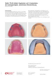
Dolder® System female parts (for bar attachment ... - Cendres Métaux
Dolder® System female parts (for bar attachment ... - Cendres Métaux
Dolder® System female parts (for bar attachment ... - Cendres Métaux

Create successful ePaper yourself
Turn your PDF publications into a flip-book with our unique Google optimized e-Paper software.
Dolder ® <strong>System</strong> <strong>female</strong> <strong>parts</strong>(<strong>for</strong> <strong>bar</strong> <strong>attachment</strong> and resilient <strong>bar</strong>)Instructions <strong>for</strong> use1 / 606.2012Application, activation, deactivation, repairs and regular servicingof <strong>attachment</strong>s should only be carried out by trained personnelusing original instruments and components.Mechanically cleaning <strong>attachment</strong>s with a toothbrush andtoothpaste can cause premature wear and tear of the functionalcomponents.Upon publication, these instructions <strong>for</strong> use supersede allprevious editions.The manufacturer is not liable <strong>for</strong> any damages due to the userdisregarding the instructions <strong>for</strong> use below.Intended UseThe <strong>bar</strong>s manufactured by <strong>Cendres</strong>+<strong>Métaux</strong> SA serve as connectors<strong>for</strong> tooth- or implant-supported removable dental prostheses.In generalTraceability of lot numbersIf <strong>attachment</strong>s are assembled from components with different lotnumbers, all relevant lot numbers have to be recorded to ensurethat they can be traced.DisinfectionAfter any fabrication or modification, the prosthetic work, incl.<strong>female</strong> part component, must be cleaned and disinfected accordingto national guidelines.When selecting the disinfectant, it is essential to ensure that:– it is suitable <strong>for</strong> cleaning and disinfection of dental prostheticcomponents.– it is compatible with the materials of the products to be cleanedand disinfected.– it has tested efficacy in disinfection.All the <strong>parts</strong> must be disinfected be<strong>for</strong>e use with a low or intermediateEPA-registered hospital disinfectant.Recommended: Cidex ® OPA Solution. Strictly follow manufacturer’sinstructions.– The device has not been evaluated <strong>for</strong> safety and compatibility inthe MR environment.– The device has not been tested <strong>for</strong> heating or migration in theMR environment.These operating instructions are not sufficient <strong>for</strong> immediate use ofthe <strong>attachment</strong>. Knowledge of dentistry and dental technology aswell as instruction on the handling of the <strong>Cendres</strong>+<strong>Métaux</strong> <strong>attachment</strong>sby an experienced person are required. Training courses areregularly provided by <strong>Cendres</strong>+<strong>Métaux</strong>, among others. The activation,deactivation, repair and periodic maintenance of <strong>attachment</strong>sshould be carried out solely by specialists. Only original auxiliarytools and <strong>parts</strong> should be used <strong>for</strong> this work.Precautions– The <strong>parts</strong> are delivered non-sterile. Proper preparation ofthe <strong>parts</strong> be<strong>for</strong>e use in patients is explained in the section« Disinfection».– Ensure the <strong>attachment</strong> is cleaned regularly to avoid soft tissueinflammation.– During intraoral use, all products should generally be securedagainst aspiration.– No cutting work should be per<strong>for</strong>med in the patient’s mouth.– The male <strong>parts</strong> must be placed parallel to the direction ofinsertion.– Undercuts must be blocked out.Further hintsFurther in<strong>for</strong>mation on soldering, casting on, laser welding etc.can be accessed on our website at www.cmsa.ch/dental in theProducts / Shop, In<strong>for</strong>mation section.Disinfection of deactivators070 200 Deactivator (Dolder ® micro) und 070 201 Deactivator(Dolder ® macro) must not be sterilised. When sterilising the abovedeactivators in the autoclave, there is a possibility that their plastichandles may be destroyed.It is there<strong>for</strong>e advisable to disinfect according to the section« Disinfection» of these instructions <strong>for</strong> use.WarningsWith patients having an existing allergy to one or several elementsof the materials contained in any one <strong>attachment</strong>, this particularproduct must not be used. With patients suspected of having anallergy to one or several of these elements contained in any one<strong>attachment</strong>, this product can only be used after preliminary allergologicaltesting and proof of a non-existing allergy.Please contact your <strong>Cendres</strong>+<strong>Métaux</strong> sales representative <strong>for</strong>further in<strong>for</strong>mation.Auxiliary instruments may contain nickel.The products carry the CE sign.See packaging <strong>for</strong> details.<strong>Cendres</strong>+<strong>Métaux</strong> SARue de Boujean 122CH-2501 Biel/BiennePhone +41 58 360 20 00Fax +41 58 360 20 11info@cmsa.chwww.cmsa.ch/dental
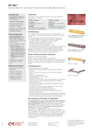
Dolder ® <strong>System</strong> <strong>female</strong> <strong>parts</strong>(<strong>for</strong> <strong>bar</strong> <strong>attachment</strong> and resilient <strong>bar</strong>)2 / 606.2012The 5 <strong>female</strong> <strong>parts</strong> concept1. Female part micro and macro (Fig. 1) E = Elitor ®Version: standardSupplied: warm straightenedFitting: polymerizedLengths: 25 and 50 mmIndication: <strong>bar</strong> <strong>attachment</strong> and resilient <strong>bar</strong>2. Female part asymmetricalmicro and macro (Fig. 2) E = Elitor ®Version: asymmetricalSupplied: warm straightenedIntegration: polymerized or resin-bondedLength: 30 mmIndication: <strong>bar</strong> <strong>attachment</strong> and resilient <strong>bar</strong>3. Female part asymmetricalmicro and macro (Fig. 3)T = Pure titaniumVersion: asymmetricalIntegration: polymerized or resin-bondedLength: 30 mmIndication: <strong>bar</strong> <strong>attachment</strong> and resilient <strong>bar</strong>4. Female part micro and macro (Fig. 4) T = Pure titaniumVersion: standardIntegration: polymerized or resin-bondedLength: 50 mmIndication: <strong>bar</strong> <strong>attachment</strong> and resilient <strong>bar</strong>5. Female part micro (Fig. 5) T = Pure titaniumVersion: com<strong>for</strong>t, with replaceableretention insertsG = GalakIntegration: polymerized or resin-bondedLength: 47.5 mm (space <strong>for</strong> 12 friction inserts)Indication: <strong>bar</strong> <strong>attachment</strong>Auxiliary <strong>parts</strong>Friction insertsG = GalakBrass spacerMicro 50 x 0.75 mm (Order No. 052 080)Macro 50 x 1.05 mm (Order No. 052 081)Indication: ensures vertical resilience of the denture and discharges<strong>bar</strong> extensions.Note: Do not put the brass spacer in tin in the mouth.Contraindication– Allergies or hypersensitivity to the chemical constituents of thematerials used. See section «Materials used».– Unilateral dentures without transverse support.– Restoration of abutment teeth with severe periodontal damage.– Hybrid dentures which are fitted with a single root cap.– Where patients have an existing allergy to one or more elementsof the <strong>attachment</strong> materials.– Unwillingness of the patient to correctly follow the aftercare/ recall instructions.– Patients with bruxism or further uncontrolled para-functionalhabits.E = Elitor ®Au 68.60 %, Pt 2.45 %, Pd 3.95 %, Ag 11.85 %, Cu 10.60 %,Ir 0.05 %, Zn 2.50 %T S– T L880 – 940 °CT = Pure titaniumG = Galakbiocompatible mouth-resistant plastic
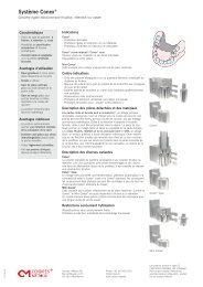
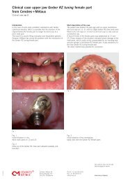
Dolder ® <strong>System</strong> <strong>female</strong> <strong>parts</strong>(<strong>for</strong> <strong>bar</strong> <strong>attachment</strong> and resilient <strong>bar</strong>)3 / 606.2012Instructions <strong>for</strong> useFemale <strong>parts</strong> 1, 2, 3, and 4The <strong>female</strong> <strong>parts</strong> can be used on prefabricated <strong>bar</strong>s in gold, titaniumand cast materials. Gold alloys, titanium and non-preciousmetal alloys are suitable as casting materials. The casting alloyused should have a 0.2 % proof stress of at least 500 N/mm 2 toensure that the cast male part has adequate strength.1. Female part E, micro and macro (Fig. 1)The <strong>bar</strong> sleeve is adjusted throughout the length of the <strong>bar</strong> toachieve maximum possible retention <strong>for</strong>ce (Fig. 6). Removeflash inside and outside. So that the <strong>bar</strong> sleeve can be securelyanchored in the plastic, it must not be shorter than 5 mm. Mount<strong>bar</strong> sleeve onto male part, then block out the space between <strong>bar</strong>and gingiva as well as implant caps or root caps. Half of the lamellaheight should remain free-moving. This allows access <strong>for</strong> theactivation instrument and reduces premature wear (Fig. 7). Theretention wings of the <strong>bar</strong> sleeve can only be bent once and withextreme caution in order to avoid breaking them off. Polymerize <strong>bar</strong>sleeve into the denture or into the cast rein<strong>for</strong>cement.2. Female part asymmetrisch E, micro and macro (Fig. 2)3. Female part asymmetrisch T, micro and macro (Fig. 3)The <strong>bar</strong> sleeve is adjusted throughout the length of the <strong>bar</strong> toachieve maximum possible retention <strong>for</strong>ce (Fig. 6). Removeflash inside and outside. So that the <strong>bar</strong> sleeve can be securelyanchored in the plastic, it must not be shorter than 5 mm. Mount<strong>bar</strong> sleeve onto male part, then block out the space between<strong>bar</strong> and gingiva as well as implant caps or root caps. Half of thelamella height should remain free-moving. This allows access <strong>for</strong>the activation instrument and reduces premature wear (Fig. 7).The asymmetric retention of the <strong>bar</strong> sleeve can be ground back,e.g. <strong>for</strong> insertion of a cast rein<strong>for</strong>cement (Fig. 8). Polymerize <strong>bar</strong>sleeve into the denture or bond into the cast rein<strong>for</strong>cement.4. Female part T, micro and macro (Fig. 3)The <strong>bar</strong> sleeve is adjusted throughout the length of the <strong>bar</strong> toachieve maximum possible retention <strong>for</strong>ce (Fig. 6). Removeflash inside and outside. So that the <strong>bar</strong> sleeve can be securelyanchored in the plastic, it must not be shorter than 5 mm. Mount<strong>bar</strong> sleeve onto male part, then block out the space between<strong>bar</strong> and gingiva as well as implant caps or root caps. Half of thelamella height should remain free-moving. This allows access <strong>for</strong>the activation instrument and reduces premature wear (Fig. 7).The retention wings of the <strong>bar</strong> sleeve can be ground back only <strong>for</strong>sectionning. Polymerize <strong>bar</strong> sleeve into the denture or bond intothe cast rein<strong>for</strong>cement.Fig. 1Fig. 2Fig. 3Fig. 4Fig. 5
Dolder ® <strong>System</strong> <strong>female</strong> <strong>parts</strong>(<strong>for</strong> <strong>bar</strong> <strong>attachment</strong> and resilient <strong>bar</strong>)4 / 606.2012Female <strong>parts</strong> 1, 2, 3 and 4Activation / Deactivation <strong>bar</strong> sleeveThe posterior lamella, which is subjected to greater loading, isactivated (Fig. 9). The anterior lamella acts as a guide surface.The relevant activator from the Activation Set (Order No. 070 198)is used to push the sleeve carefully inwards <strong>for</strong> activation. Thedeactivator (Order No. 070 200 micro sleeve, 070 201 macrosleeve) is pushed into the sleeve to deactivate an excessively tight<strong>bar</strong> sleeve until the required friction is attained (Fig. 10).5. Female part T (with replacebal friction inters G) (Fig. 5)Six yellow (light friction) and six red (normal friction) friction insertsare supplied with the <strong>bar</strong> <strong>female</strong> part. The length of the <strong>bar</strong> <strong>female</strong>part can be shortened every 3.5 mm using the separating groove.The groove is also used as a guide <strong>for</strong> the cut-off wheel whenseparating (Fig. 11). Remove any flash (Fig. 12) with a rubberpolisher after separating. After fitting the friction inserts, place the<strong>female</strong> part on the <strong>bar</strong> and block out the space between the <strong>bar</strong>and the gingiva as well as the root and implant caps (Fig. 13) andthen resinbond or polymerise into place.Fitting the plastic insertPlace the friction insert G on the insert positioner (Order No.0700 0034) (Fig. 14). Apply a little pressure by pressing on the<strong>female</strong> part to find the correct position of the friction insert(Fig. 15). As soon as the insert engages in the groove (clearlyaudible), push the friction insert in to its final position (Fig. 16).The insert makes an audible click when it engages. Severalinserts, even inserts with different degrees of friction, can be useddepending on the amount of retention <strong>for</strong>ce required (Fig. 17).Only a few inserts, the ones with minimum friction, should beused <strong>for</strong> 2 – 4 weeks so that the patient can quickly become accustomedto handling the new restoration.Note:– Do not use the friction inserts used <strong>for</strong> laboring the denture <strong>for</strong>the patient.– Newly fitted friction inserts:– The inserts may become displaced laterally after fitting. After aday in situ they adjust to their correct position and can no longerbecome displaced.– The correct retention <strong>for</strong>ce is attained after about two weeks.The retention <strong>for</strong>ce is slightly higher initially.– Do not re-use friction inserts once they have been used.Removing the plastic insertPress the two ends of the lamella together with tweezers (OrderNo. 070 347). This disengages the insert from the retention andallows it to be easily removed.Fig. 6Fig. 7Fig. 8Fig. 9Fig. 10