PGC 9000 VC
PGC 9000 VC
PGC 9000 VC

You also want an ePaper? Increase the reach of your titles
YUMPU automatically turns print PDFs into web optimized ePapers that Google loves.
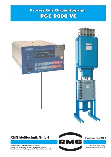
Process Gas Chromatograph<strong>PGC</strong> <strong>9000</strong> <strong>VC</strong>RMG Meßtechnik GmbHPublication No. 3.572-EP.O.Box 280 · D-35502 Butzbach (Germany)Phone: +49 (0)6033 897-0 · Fax: +49 (0)6033 897-130E-mail: messtechnik@rmg.de · Web site: http://www.rmg.deReliability in gas supply -single-sourced across the board
Fields of applicationThe <strong>PGC</strong> <strong>9000</strong> <strong>VC</strong> process gas chromatographanalyzes the composition of natural gas and determinesthe 11 major gas components as contents inmol%. From these contents, the following variablesare calculated on the basis of the characteristics of thegas components (as per ISO 6976): superior calorificvalue (Hs,n), inferior calorific value (Hi,n), standarddensity ( n), relative density (rd) and Wobbe index(Ws,n and Wi,n). These variables can be outputtedthrough analog or digital interfaces, just as the contentsof the individual gas components.ApprovalThe <strong>PGC</strong> <strong>9000</strong> <strong>VC</strong> process gas chromatograph hasbeen approved for custody transfer measurement ofthe superior calorific value, standard density andcarbon dioxide content.The <strong>PGC</strong> <strong>9000</strong> <strong>VC</strong>, therefore, provides the analyticaldata required for PTZ correction, including the calculationof the K coefficient as per GERG 88-S, whilesatisfying the requirements of custody transfermeasurement.Operating rangesCustody transfer measurement can be performed inthe following operating ranges:Component Content (mol%)Nitrogen 0 - 20Methane 70 -100Carbon dioxide 0 - 20Ethane 0 - 20Propane 0 - 5i-Butane 0 - 2n-Butane 0 - 2neo-Pentane 0 - 0.3i-Pentane 0 - 0.3n-Pentane 0 - 0.3C6+ 0 - 0.3Standard density: 0.7 - 1 kg/m3Superior calorific value: 7.0- 14 kWh/mMeasuring uncertaintyAs to the variables measured in compliance withcustody transfer measurement requirements, the limitsfor the measuring uncertainty are:Superior calorific value: < ±0.25%Standard density: < ±0.25%Carbon dioxide content: < ±0.3 mol%3Method of operationAt the heart of the gas chromatograph lies a capillarytube, what is called the column. This capillary tube,which is lined with a specific silicone material, servesto separate the individual components of a gas mixture.The column is continuously swept with helium, whichis used as the carrier gas for the transport through thecolumn. For analytical purposes, a precisely meteredquantity of natural gas is injected into the helium flowat the inlet of the column. On their way through thecolumn, the molecules of the natural gas componentshit the column lining and are retained there for a shorttime (adsorption). Since the molecules of the variousgas components are retained on the wall for differentperiods of time, the individual components leave thecolumn at different times. Therefore, the gas componentscan be identified by these times.Gas moleculetSeparation in timeat the inletColumn wallAfter leaving the column, the gas flows through athermal conductivity detector which measures thevolume contents of the individual gas components.Each time a gas component leaves the column, thethermal conductivity of the gas changes, which ismeasured by the detector. From this change, thevolume content of the gas component concerned canbe calculated.In order to ensure constant accuracy, the gas chromatographis automatically calibrated at 7-day intervals.For this purpose, a gas mixture of which the compositionis known is analyzed.ConstructionLiningAdsorptionSeparation of gas componentsby differentbreakthrough timesThermal conductivitydetectortSeparation in timeat the outletThe <strong>PGC</strong> <strong>9000</strong> <strong>VC</strong> process gas chromatographconsists of the following components: The sampling probe is used to take samples of themeasuring gas to be analyzed from the gas pipe. The pressure reducer reduces and stabilizes thepressure of the measuring gas.2
Sampling probeIsolating couplingShut-off valveProbe, dia. 6 mmChamferagainst theflow directionCouplingSampling probe of the type PES 50app.50 mmGas pipe DN100-800Analytical pipe(high-quality steeldia. 6x1)Heat insulationWeldolet(1/2"-14NPT)Bore hole(dia. 8 mm)in the gas pipeThe sampling probe is chamfered at its opening. Thisresults in less condensate reaching the analytical pipe.An isolating coupling electrically isolates the gas pipeand the analytical pipe. If the alternatively availabletype PPS 02-R is used, the probe can be extended orretracted under pressure by means of a special tool.Pressure reducerThe DRS 200 pressure reducer reduces the inletpressure from a maximum of 100 bar to an outletpressure in the range of 2 to 7 bar. It is fitted into aheated and insulated protective polyester cabinet withan inspection window.The pressure reducer includes the followingcomponents:Inlet filterTest tap with measuring coupling and shut-off valvePressure regulatorUpstream / downstream pressure gauge at thepressure regulatorSafety relief valveExplosion-protected solenoid valve for safetyshutdown (option)The pipe from the sampling probe to the pressurereducer can be heated. In this case, the heater isconnected to the pressure reducer.The blow-off pipe of the safety relief valve and thebreathing pipe of the pressure reducer are designedas pipes with a diameter of 12 mm.The DRS 200 pressure reducer is available eitherfitted into a bold-on case for wall mounting or mountedon a stand. If the stand-mounted version is providedwith a weather shield, it can also be installed outside.Blow-off pipe of the safety reliefvalve (pipe dia. 12 mm)Meas.gasoutletBreathing pipe of thepressure regulator (pipe dia. 12 mm)Explosion-protected solenoid valve 24V/DC(closed at zero current)Flow monitor of the safetyrelief valveSafety relief valveTest tap(measuring coupling)Pressure reducing valve 100/2 to 7 bar746 mmFilterExplosion-protected room thermostatExplosion-protected heating 100 WBore holedia. 11StopcockVenting520 mm612 mm660 mmMeas.gasinletDRS 200 pressure reducer (wall-mounting case)4
CP 2002 measuring elementThe CP 2002 is available either as a "Non-Ex" or "Ex"version with an explosion-proof enclosure. The caseincorporates the measuring mechanism with twocolumns, the electronic control system and the pressuretransmitters for the measuring and carrier gases.Furthermore, the gas distribution system is locatedinside the case, i.e. a valve block used for switchingbetween the individual measuring and calibration gasinlets. By arranging the valves in a specific way("double block and bleed"), it is ensured that the gas tobe analyzed is not contaminated with gas from otherinlets.A total of up to four measuring gas flows can be analyzed.The sequence of connecting the differentmeasuring gases and the number of analyses to beperformed can be programmed through the analyticalcomputer.By using a bypass, part of the measuring gas can bedischarged without passing the measuring mechanism.This increases the flow in the supply pipe, andall the time current measuring gas is analyzed. Theflow in the bypass can be adjusted via a needle valve.The location for installation of the CP 2002 measuringelement requires no air conditioning. The ambient temperaturemay vary in a range from -10 to 55°C withoutrestriction. All that is needed to monitor the temperatureis a min./max. thermometer; a temperature recorderis not required.Explosion-protected ("Ex") designNot explosion-protected ("Non-Ex") designOutlet pipeE1E2Outlet pipe E1E2343 4112Gas inlets:A) Carrier gas(inlet pressure 5.5 bar)B) Internal calibration gas(inlet pressure 2 to 3 bar)C) External calibration gas(inlet pressure 2 to 3 bar)M) Measuring gases(inlet pressure 2 to 3 bar)21850551850ABCM1M2M3M41-stream2-stream3-stream4-streamoperation1-stream2-stream3-stream4-streamoperationABCM1M2M3M41684504504004001) CP 2002 measuring element with valve control system andexplosion-proof enclosure2) EEx e connection box3) Variable-area flowmeter for the bypasses of the measuring gases4) Variable-area flowmeter for the outlet pipe of the measuring mechanism5) Gas inlet module with filter(The gas inlet can optionally be located on the left or right side)Supply pipes for connections A, B, C:1/8“ pipe with Swagelok connectionSupply pipes for connections E2, M1 through 4:6 mm pipe with Swagelok connectionSupply pipe for connection E1:12 mm pipe with Swagelok connection5
Gas supply unitThe gas supply unit accommodates the gas cylinders(10 ) for the carrier gas (helium) and the calibrationgases (special designs with 50 carrier gas cylindersare possible). The "internal" calibration gas is used forthe weekly automatic calibration. It contains a gasmixture of a known composition of all the 11 gas componentsanalyzed by the <strong>PGC</strong> <strong>9000</strong> <strong>VC</strong>. The "external"calibration gas is used for the annual inspectionduring recalibration and its composition corresponds tothat of the measuring gas which is mainly analyzed.A cylinder heating prevents calibration gases separatingand heavy gas components condensing on thecylinder walls.One location space of the gas supply unit is intendedto take up a spare carrier gas cylinder. A manual orautomatic switching unit can be installed for the twocarrier gas cylinders.A 10 carrier gas cylinder lasts for approximately sixmonths, while a calibration gas cylinder lasts for fiveyears in normal operation.5304204D1D21 26571450ABC3Carrier gas 10 litersCarrier gas 10 litersInt. calibrationgas 10 litersExt. calibrationgas 10 liters660ABC13001) Upstream pressure reducer with safety relief valve forinternal calibration gas2) Upstream pressure reducer with safety relief valve forexternal calibration gas3) EEx e connection box for explosion-protected cylinder heatingOptions:4) Automatic or manual switching unit for two carrier gas cylinders5) EEx i connection box for contact manometer (switching unit)6) Temperature controller7) Explosion-protected solenoid valve for internal calibration gas cut-offConnections:A) Carrier gas outletB) Internal calibration gas outletC) External calibration gas outletD) Blow-off pipe (carrier gas)E) Blow-off pipe (internal calibration gas)The outlets A, B, C can optionally be locatedon the left or right side.6
GC <strong>9000</strong> analytical computerThe GC <strong>9000</strong> analytical computer controls theanalytical process and calculates the contents of thegas components in per cent from the measured data.From these contents, it calculates the superior calorificvalue and the standard density as per ISO 6976, aswell as the Wobbe index, relative density and inferiorcalorific value for secondary applications. Operation ofthe process gas chromatograph is also performedthrough the analytical computer. Here, operatingmodes can be selected or printouts started.The analytical computer is a variant of the RMG ERZ<strong>9000</strong> Flow Computer. It offers the following features: Ease of operation: All configuration data andmeasured and calculated data are stored in aneasy-to-survey table. All the cells of this table canbe reached and displayed by pressing arrow keys.Moreover, major variables, such as the superiorcalorific value, can be directly accessed by pressinga single key. Bus interface (RS 485) to connect to a DSfG bus,MODBUS or RMG bus, with the RMG bus beingexclusively used to transfer data from the analyticalcomputer to the volume corrector. Front interface for reading out data, parameterizationor servicing. Calculation of hourly, daily and monthly meanvalues for superior calorific value, inferior calorificvalue, standard density, relative density, CO2contentand Wobbe index. Rack-mounting case for installation into 19" racks. Installation at a distance of up to 1,000 m from theCP 2002 measuring element is possible.DS 900 data loggerThe approval of the <strong>PGC</strong> <strong>9000</strong> <strong>VC</strong> process gaschromatograph requires that a printer is connected tothe analytical computer for outputting analyticalresults, calibration reports, etc. As an alternative, theDS 900 data logger, which represents a completeprinter substitute, has been approved. With the datalogger, large quantities of paper are no longer required,and there will be no more disturbances caused bypaper jams inside the printer.The DS 900 data logger is to be connected to theprinter interface of the GC <strong>9000</strong> analytical computerinstead of a printer.The DS 900 data logger is an industrial PC with thefollowing features: Suitable for use with a 1-stream or multi-stream gaschromatograph with up to a maximum of fouranalyzed gas streams. Data are stored on two hard disks with a capacity of1.6 gigabytes each, which is sufficient for at leastthree years. The redundant storage of data on thetwo hard disks ensures a high degree of dataprotection. Data are stored chronologically and can be browsedthrough using a joystick. Text is stored in the ASCII format, while graphics(chromatograms) are stored in the PCX format. Thisenables data to be processed using standardprograms. 3.5"floppy disk drive for archiving data andinstalling new software versions. Option for connecting a printer. Standard 19" slide-in case.7
Process Gas Chromatograph<strong>PGC</strong> <strong>9000</strong> <strong>VC</strong>SpecificationsCP 2002 Measuring ElementAmbient temperature-10°C to +55°C, no air conditioning requiredDegree of protection- Explosion-protected design ("Ex") IP 54- Not explosion-protected design ("Non-Ex") IP 43"Ex" device protection typeCarrier gasWeight- "Ex" design 75 kgs- "Non-Ex" design 60 kgsPower supplyPower requirementII2 G EEx de IIB T5Helium 5.024VDC/230VAC80 WProcess connections- Carrier, measuring and calibration gases 1/8” Swagelok- Exhaust gas 6 mm SwagelokGas consumption- Carrier gas approx. 8 m /min continuously- Measuring gas approx. 35 mduring purgingGas Supply UnitDimensionsPower supplyPower requirementGC <strong>9000</strong> Analytical ComputerDimensionsPower supplyPower requirementOutputsInterfacesDS 900 Data LoggerDimensionsPower supplyPower requirementW x H x D = 1300 x 1450 x 500 mm230 V AC100 W per heated cylinderW x H x D = 213 x 128.4 x 300 mm (42 DU / 3 HU)24VDC/230VAC30 WRelay contact for alarm indication(potential-free, max. 24 V, 100 mA)4 electrically isolated analog outputs(potential-free, 0/4-20 mA, assignment freely selectable)Front panel:1 x RS 232 CRear panel: 4 x RS 232 C1 x DSfG or RMG busW x H x D = 426 x 128.4 x 280 mm (84 DU / 3 HU)24VDC/230VAC55 WRMG Meßtechnik GmbHPublication No. 3.572-EP.O.Box 280 · D-35502 Butzbach (Germany)Phone: +49 (0)6033 897-0 · Fax: +49 (0)6033 897-130E-mail: messtechnik@rmg.de · Web site: http://www.rmg.deIssue: 01/2003Subject to technical modificationwithout notice