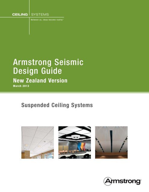
Seismic Installations and Armstrong Ceiling Systems
Seismic Installations and Armstrong Ceiling Systems
Seismic Installations and Armstrong Ceiling Systems

You also want an ePaper? Increase the reach of your titles
YUMPU automatically turns print PDFs into web optimized ePapers that Google loves.
Suspended <strong>Ceiling</strong> - <strong>Seismic</strong> DesignAll structures <strong>and</strong> parts of structures including suspended ceilings shall be designed to resist earthquakeactions as set out in NZS 1170.5. In previous earthquakes throughout history, suspended ceilings haveshown a tendency to perform poorly. This may be due to the fact that they are often overlooked <strong>and</strong> thecode requirements for seismic design are low. It is important that suspended ceilings are designed suitablyto ensure they perform in a seismic event. The failure of suspended ceilings can cause evacuation paths tobe blocked which could be a hazard to life safety. Failure can also cause unnecessary delays in resumingbusiness especially if the rest of the structure has sustained no damage.The purpose of this guide is to provide a method for the seismic design of suspended grid <strong>and</strong> tile ceilingsystems. It has been designed to meet the requirements of NZS 1170.5 – Structural Design Actions –Earthquake actions. From this guide, a grid type, bracing requirements <strong>and</strong> fixing types can be designed.Please note that this guide is not suitable for all suspended ceilings <strong>and</strong> those which fall outside its’ scopemust be designed by a suitably qualified structural engineer.1
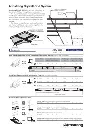
Table of ContentsSuspended <strong>Ceiling</strong> - <strong>Seismic</strong> Design 2Table of Contents 3Design Statement 3Limitations <strong>and</strong> Assumptions 4Design Considerations 4How to Use This Document 5Bracing Layout Options 6Perimeter Fixing 6Back Bracing 6<strong>Seismic</strong> Loading 8Bracing Option Layouts 1 & 2 (Perimeter Fixing) 9Perimeter Connection Details 10Bracing Layout Option 3 (Back Bracing) 11Installation of Bracing 12Summary Sheet 14<strong>Seismic</strong> Gap Options <strong>and</strong> other <strong>Armstrong</strong> Details 15List of seismic factors for specific towns/cities. 17Design StatementKnowles Consulting Limited (KCL) has been engaged by Forman Building <strong>Systems</strong> to provide a suspendedceiling seismic design guide which is accurate <strong>and</strong> easy to follow. The guide has been prepared to meet therequirements of the NZ building codeTesting of the grids was undertaken to determine the compression <strong>and</strong> tension capacities. Testing of theperimeter fixings was also undertaken. The values from this testing have been used in this guide.2
Limitations <strong>and</strong> AssumptionsLimitations■ This guide may only be used to design suspended ceilings with <strong>Armstrong</strong> Prelude XL <strong>and</strong> SuprafineXL ceiling grids.■ This guide may only be used for buildings in New Zeal<strong>and</strong>.■ The ceiling system must meet both gravity <strong>and</strong> seismic load requirements.■ All other Forman & <strong>Armstrong</strong> brochures, manuals <strong>and</strong> codes must be adhered to.■ All individual objects weighing over 10kg shall be braced separately unless specifically designed by astructural engineer. Similarly ceiling tile must weigh less than 10kg each unless a structural engineeris consulted.■ The perimeter shall be nogged continuously at ceiling level if ceiling is fixed at perimeter. This is toensure that the loads can be transferred from the ceiling into the perimeter support. If the perimeteris not continuously nogged, the perimeter fixing option may NOT be used.■ A structural engineer for the building must check all lateral loads can be resisted by the supportstructure. The support structure must be both strong enough <strong>and</strong> stiff enough.■ <strong>Ceiling</strong> grid tees must be spaced at a maximum of 1.2m centres.■ Partition walls must not be braced by the ceiling grid unless designed by a qualified structuralengineer.■ The ceiling must not be a structural component of the building. It may not be used to transfer loadsbetween structural elements of the building.■ For a Level 4 importance building (e.g. hospital or police station) a qualified structural engineer mustbe consulted.■ For ceilings with a plenum of less than 300mm back bracing cannot be used without consulting aqualified structural engineer.Assumptions■ The period of the ceiling is assumed to be T≤0.75s■ Assume ceiling grid ductility µ=1.03
Design Considerations■ <strong>Ceiling</strong>s should not be attached to two opposite walls unless there is a seismic gap between them.This is because of the forces that can be induced in the ceiling grid if differential displacementsoccur between the perimeter structures.■ <strong>Ceiling</strong>s should not be braced to both a wall <strong>and</strong> the roof/structure above due to differentialmovement.■ If the building is importance level 4 (hospital, police station etc.) a qualified structural engineer mustbe consulted in the design of the ceiling.How to Use This Document1 Determine the seismic zone Z value using the map or using the town/city list found at the back of thedocument.2 Determine the ceiling height factor H, from the tables.3 Input values to determine the total ceiling weight. All elements which are supported by the ceiling needto be included.4 Determine ceiling slope factor from tables.5 Calculate seismic force, Fp using the tables.6 Calculate total force, Ft using bracing layout option 1.7 Check with the building engineer to see if the perimeter structure can be used to brace the ceiling.8 Choose a grid <strong>and</strong> connection type. If the grid or connection type does not work try bracing layoutoption 2. If neither perimeter fixing option works proceed to step 8 <strong>and</strong> use back bracing layout(option 3). Follow steps 8-9 only for back bracing option.9 Choose a back bracing type.10 Choose the back bracing spacing so that the maximum area allowed <strong>and</strong> maximum brace spacing isnot exceeded.11 Fill in the Summary Sheet.4
Bracing Layout OptionsThere are three different options for bracing the ceiling against lateral loading. Options 1 <strong>and</strong> 2 involvebracing the ceiling to the perimeter <strong>and</strong> option 3 involves bracing back to the structure above. Option 1 isfor smaller ceilings with lower lateral loads, option 2 is for larger ceilings <strong>and</strong> option 3 is for ceilings whereoptions 1 <strong>and</strong> 2 do not work.Perimeter FixingOption 1(Perimeter fixing onadjacent edges)<strong>Ceiling</strong> is fixed to the perimeter on twoadjacent sides <strong>and</strong> a seismic sliding jointis used on the opposite sides. Lateralloads are transferred from the ceiling tothe perimeter through a perimeter fixing.Fixed ConnectionA1Sliding ConnectionFixed Connection<strong>Seismic</strong> Gap (typ.)A1Sliding ConnectionOption 2(Perimeter fixing on more thantwo edges)The ceiling is split up into smallersections using seismic joints. Theceiling can then be fixed to theperimeter on opposite sides. Lateralloads are transferred from the ceilingto the perimeter throughperimeter fixings.A1A1Sliding ConnectionA3A2A4Fixed ConnectionBack BracingOption 3(Back bracing)<strong>Ceiling</strong> GridBraced Back toStructure AboveSliding ConnectionAround Entire PerimeterThe ceiling is braced back to thestructure above with compression struts<strong>and</strong> tension wire braces or diagonaltension/compression struts. A seismicsliding joint around the entire perimeteris required as the ceiling may not bebraced to both the structure above <strong>and</strong>5<strong>Ceiling</strong> GridBraced Back toStructure Abovethe perimeter.Sliding ConnectionAround Entire Perimeter<strong>Ceiling</strong> GridBraced Back toStructure AboveSliding ConnectionAround Entire Perimeter
Job Name:Job Number:<strong>Seismic</strong> Loading<strong>Seismic</strong> ZoneChoose a seismic zonefrom the adjacent map.Alternatively selectZ Value from town/citylist on page 16Zone Z Value 9m 2.0Calculate the total ceiling weight. All elements that are supported by the ceiling grid must be included. Notethat no individual element may weigh more than 10kg each. The total service load must be taken as at least3kg/m². See example for calculation of lighting weight.<strong>Ceiling</strong> Tilekg/m²Gridkg/m²Service Load* Lighting kg/m²Insulationkg/m²Otherkg/m²Subtotalkg/m²Total Wp =kg/m²Light Weight = 4 kgLight Spacing = 2.4 x 2.4m = 5.76m 2Lighting Load = 4 ÷ 5.76 = 0.7 kg/m 2*Minimum services load is 3kg/m²6
Suspended <strong>Ceiling</strong> <strong>Seismic</strong> Design FormJob Name:Job Number:<strong>Ceiling</strong> SlopeIn the case of a sloping ceiling the seismic forces carried by the grid are increased due to the angle of theceiling. Choose a ceiling slope factor from the table.<strong>Ceiling</strong> SlopeSlope Factor0° 1.00010° or less 1.01520° or less 1.06430° or less 1.15540° or less 1.305SEISMIC FORCEInsert the relevant choices <strong>and</strong> multiply them together to find the seismic force. If there is any doubt astructural engineer should be consulted.<strong>Seismic</strong> Zone Z value Height Factor*, H <strong>Ceiling</strong> Slope Factor <strong>Ceiling</strong> Weight, Wt <strong>Seismic</strong> Force, FpX X X =X X X =*Height of ceiling bracing from ground level. If the ceiling is braced to the perimeter use the ceiling height, if the ceiling is braced to the roof/structure above use the roof height.7
Job Name:Job Number:Bracing Option Layouts 1 & 2 (Perimeter Fixing)Grid <strong>and</strong> Connection TypeEnter the values below <strong>and</strong> multiply them together to calculate the maximum force in the main <strong>and</strong> crosstees. This calculation is only required for option 1 or 2 bracing.<strong>Seismic</strong> Force, Fp = Tee Spacing (m) Tee Length* (m) Total Force Ft =X Main Tee X Main Tee = Main TeeX Cross Tee X Cross Tee = Cross Tee*Tee Length - Option 1 (Fixed on one side) = Length from wall to wall.- Option 2 (Fixed on two sides with seismic gap in middle) = Maximum length from wall to seismic gap.Grid <strong>and</strong> Connection TypeChoose a grid type from the options below so that the force on the grid is less than the grid capacity, i.e. Ft≤ Fg. If none of the grid types work a different bracing option will need to be used.Suspended <strong>Ceiling</strong> <strong>Seismic</strong> Design FormGrid TypeSuprafine XL 15mmPrelude XL 24mmAllowableTee Force, Fg =Main Tee 100Cross Tee 60Main Tee 100Cross Tee 60OK?AllowableFixed Connection Type Force, Fc =3.2Φ Alum Rivet 704.0Φ Alum Rivet 100BERC2 Clip 60OK*?* Is the Maximum Total Force, Ft ≤ Fc, Allowable Force?Free Connection Type (Circle One)BERC2 Clip <strong>Seismic</strong> Channel NoneCalculate the maximum allowablelength of Main <strong>and</strong> Cross TeesAllowable Force(Tees <strong>and</strong> Connections)* Tee Spacing (m)<strong>Seismic</strong>Force, Fp =Maximum AllowableLength (m)Main Tee ÷ ÷ = Main TeeCross TeeCross Tee*Minimum allowable force from chosen grid connection <strong>and</strong> tee type above.8
Job Name:Job Number:Suspended <strong>Ceiling</strong> <strong>Seismic</strong> Design FormPerimeter Connection DetailsFixed ConnectionIt is very important that the grid is fixed to the perimeter properly so that the loads can be transferredfrom the ceiling into the building structure. The following criteria must be followed when attaching to theperimeter:■ The wall angle must be fixed to the building structure within 20mm of the grid fixing.■ The wall angle must be fixed at 600mm centres minimum. See table below for fixing type.■ When using BERC2 clips for fixing option ensure it is screwed to BOTH the wall angle <strong>and</strong> tee.■ Required edge distances must be followed when fixing rivets.■ Ensure building perimeter structure has been reviewed by the building engineer to check that it canresist lateral loads.Sliding ConnectionIt is important that the sliding connection is built properly so that additional loads are not experienced bythe grid.■ The BERC2 Clip must be screwed to the wall angle. The screw connecting the grid <strong>and</strong> clip must notbe tightened <strong>and</strong> placed centrally in the sliding slot.■ The end of the grid must be located 19mm away from the wall angle.■ When using a seismic channel a hanger must be placed within 200mm of the perimeter.Wall angle perimeter fixing typePerimeter Material Fixing Type*TimberNo. 8 x 51mm screwSteel14G Tek screwConcreteRamset 6x30mm Dynabolt or equivalent*The fixing types in the table above may be exchanged for an alternative fixing with a safe working strengthof greater than 1.5kN that is suitable for seismic loading. (e.g. Concrete Screw Anchors are not suitable forseismic loadings)9
Job Name:Job Number:Bracing Layout Option 3 (Back Bracing)This section is to be used only for bracing option 3 where the grid is braced back to the structure above.This option is required when the forces in the grid are too high to allow perimeter fixing. Choose a bracetype from the options below <strong>and</strong> calculate the maximum ceiling area allowed per brace. Any <strong>Armstrong</strong> gridmay be used as the back-bracing strengths govern the design.Bracing TypeBrace A – Rondo 64x0.50 BMT Stud Strut with 4/2.5 dia wire diagonals.Brace B – Rondo 64x0.50 BMT Strut with 2/64x0.50 BMT Stud diagonals.Brace C – Rondo 92x0.75 BMT Strut with 2/92x0.75 BMT Stud diagonals.Maximum Area per BraceCalculate the maximum ceiling area allowed per brace for a chosen brace <strong>and</strong> plenum height. If the maxarea per brace is too small a stronger bracing type may need to be chosen.Suspended <strong>Ceiling</strong> <strong>Seismic</strong> Design FormPlenumDepth (m) Brace A Brace B Brace C0-0.6 90 250 3000.6-1.0 90 250 300<strong>Seismic</strong>Force, Fp =1.0-1.4 90 250 300 ÷ =1.4-1.8 90 160 3001.8-2.4 90 90 170Max Area PerBrace (m²)Area per BraceChoose the spacing of braces <strong>and</strong> multiply the numbers together to get the area of ceiling per brace. At leastevery second main tee should be braced to avoid the ceiling having to perform as a diaphragm. The area perbrace must be less than the maximum area calculated above. The spacing of the braces in both directionsis governed by the spacing of tees <strong>and</strong> also the spacing of structural elements in the roof above (i.e. purlinspacing). If the spacing of braces seems too close use a stronger brace.Brace Spacing AlongMain TeeBrace SpacingAlong Cross Tee*Area = X =Area PerBrace (m²)OK?*Braces should be spaced a maximum of every second main tee (typically 2.4m) <strong>and</strong> a maximum of 12m along the main tees.Brace Fixing TypesThe table below gives the minimum connection for the different bracing types.Brace A Brace B Brace CSteel 2x 14G Tek Screw 4x 14G Tek Screw 4x 14G Tek ScrewConcrete 2x M6x30 Dynabolt 2x M6x30 Dynabolt 2x M6x30 DynaboltTimber 2x No 8x51 screw 4x No 8x51 screw 4x No 8x51 screwGrid Tee 2x14G Tek screw 3x14G Tek screw 3x14G Tek screw10
Job Name:Job Number:Suspended <strong>Ceiling</strong> <strong>Seismic</strong> Design FormInstallation of BracingIt is important that once the brace type is chosen it is properly installed. The following criteria must be metwhen installing the bracing to the roof:■ The compression strut must be connected to the Main Tee only <strong>and</strong> be within 50mm of a Cross Teeconnection. See table on page 11 for fixing types.■ The diagonal wires are to be angled at no more than 45° from the plane of the ceiling.■ Braces must be placed a minimum of half the spacing distance from the perimeter.■ At least every second main tee should be back braced. The first Main Tee from the edge of theceiling should always be braced. Back braces should be installed in a staggered formation forstability (refer example ceiling layout). It is preferable if every main tee is back braced.■ A ceiling may not be both back braced <strong>and</strong> fixed to the perimeter.■ Tension wires are to be fixed to web holes not bulb slots <strong>and</strong> tied with a minimum of 3 turns.■ Plenum depths greater than 1.4m may need a perimeter gap of greater than 19mm provided by theBERC2 clip. Speak to the buildings structural engineer to determine the gap required.■ Required edge distances must be followed when fixing rivets, screws etc.64 x 0.5 BMT Rondo Stud45°45°2.5Ø Tension Wire45°45°Cross Tee50 Max.80 Max.2 x 14G Tex Screws1-BRACE AMain Tee64x0.5 BMT or92x0.75 BMT Rondo stud64x0.5 BMT or92x0.75 Rondo studc/w 4x14G Tek screws,two each side of vertical stud45°45°64x0.5 BMT or92x0.75 Rondo studc/w 4x14G Tek screwsto vertical stud50 Max.3x14G Tek screws112-BRACE B & CCross TeeMain Tee
Summary SheetJob Name:Site Location:<strong>Ceiling</strong> Level:Job Number:Fill out the Summary sheet below from the types chosen in the preceding sheets.Grid TypeMain TeeCross TeeSuprafine XL15mmSuprafine XL15mmPrelude XL24mmPrelude XL24mm@@m centres.Max Length =m centres.Max Length =mmSuspended <strong>Ceiling</strong> <strong>Seismic</strong> Design FormPerimeter FixingFixed Connection 3.2Φ Rivet 4.0Φ Rivet BERC2 ClipFree Connection BERC2 Clip Sliding Joint (Hanger ≤ 200mm)<strong>Seismic</strong> Gap (Circle one)<strong>Seismic</strong> Joint Clip SJMR1524mm grid<strong>Seismic</strong> Joint Clip SJMR915mm gridNoneBack Bracing Type (Bracing Layout Option 3 Only)Plenum Depth:Brace Spacing: Between Main TeesBetween Cross TeesmmBrace Type (circle one) Bracing Description Fixing to Structure Above(see fixing type table)Brace ABrace BBrace CRondo 64x0.50 BMTStud Strut with 2.5 diawire diagonals.Rondo 64x0.50 BMTStrut with 2/64x0.50BMT Stud diagonals.Rondo 92x0.75 BMTStrut with 2/92x0.75BMT Stud diagonals.Fixing to Tee(see fixing type table)Markup Plan Attached? (circle one)YesNo12
<strong>Seismic</strong> GAP Options■ BERC2 Clip■ <strong>Seismic</strong> Joint Clip – Main Tee■ <strong>Seismic</strong> Joint Clip – Cross Tee<strong>Seismic</strong> Joint Clip – Main BeamProduct DescriptionMaterialsA. General: Commercial-quality cold rolled hot dippedgalvanized steel, chemically cleansedB. Components:a. <strong>Seismic</strong> Joint Clip, stamped, unfinished, singlepieceunit with slots <strong>and</strong> screw holesb. Expansion Sleeves, stamped, exposed faceprefinished in baked polyester paintNote: Not suitable for use with Vector ® panels.ExpansionSleeve<strong>Seismic</strong>Joint Clip –Main BeamBucket # Description Dimension Color/Finish■ SJMR15<strong>Seismic</strong> Joint Clip – Main Beamfor 24mm grid100mm x 25mmnominalUnpainted■ ES4100mm Expansion Sleevefor Prelude 24mm Main Beam100mm x 24mmnominalWhite■ SJMR9<strong>Seismic</strong> Joint Clip – Main Beamfor 19mm grid100mm x 25mmnominalUnpainted■ ES49100mm Expansion Sleevefor Suprafine ® 19mm Main Beam100mm x 19mmnominalWhite<strong>Seismic</strong> Joint Clip – Cross TeeProduct DescriptionMaterialsA. General: Commercial-quality cold rolled hot dippedgalvanized steel, chemically cleansedB. Components:<strong>Seismic</strong> Joint Clip, stamped, unfinished,two-piece unit with slotsItem # Description Dimension Color/Finish■ SJCG<strong>Seismic</strong> Joint Clip2 pcs required/joint125mm x 38mmnominalUnpainted13
3/4"4"1-1/16"1-1/2"2-3/8"Simple to Install with these Easy StepsHow to Install the <strong>Seismic</strong>Joint Clip – Main BeamStep 1: Determine which splices will receive the separation joint bydividing the total area into sections not greater than 250m 2 . Attacha hanger wire within 75mm of the splice that will receive the clip.Step 2: Install complete grid system. Follow typical procedures exceptthat all main beam splices must line up across the space.Step 3: Prepare the main beam splice to receive the separation jointclip by cutting the locking tab from the left side of the connection <strong>and</strong>removing 19mm from the end of the beam on the right.Step 4: Install the clip using the screws provided. Screws #1 <strong>and</strong> #2install through the holes in the clip <strong>and</strong> into the right-h<strong>and</strong> main beam.#3#4IndexingNib#1#2Step 5: Align the indexing nib with the lower hole on the left-h<strong>and</strong>main beam <strong>and</strong> insert screws #3 <strong>and</strong> #4 into the upper holes.10mm fromCenterlineStep 6: Snap ES4 or ES49 expansion sleeve over the gap at the faceof the main beam <strong>and</strong> crimp the four corners with a pair of pliers.Step 7: Install SJCG cross tee separation joint clips at one end of everycross tee that spans the area of main beam separation.<strong>Seismic</strong> Rx ® ApproachAttached WallBERC2 Clips OR Pop RivetsB or PAttached WallB or P B or PB8" Max.8" Max.BXX7/8"7/8"BPop RivetUnattached WallBBXXBXX8" Max.BScrew optional2' o.c.Unattached Wall7/8" 3/4"BXBXB BUnattached WallX Hanger WireB BERC or BERC2 ClipP Pop Rivets<strong>Seismic</strong> Rx Code Compliant Solutions <strong>and</strong> Benefits (ESR-1308)■ Narrow, sleek aesthetic with st<strong>and</strong>ard22mm molding■ Eliminates installation <strong>and</strong> aesthetic problemsassociated with 50mm wall angle■ Lower cost solution■ Better access to the plenum■ Eliminates stabilizer bars■ Eliminates visible pop rivets through thewall angle■ More profiles from which to choose■ Perimeter Support wires within 400mm■ Attached grid on two adjacent wallswith the BERC2 clip or pop rivets■ BERC2 clip with 19mmclearance on unattached walls■ Allows for minimum 19mmmovement of cross tee or main beam towards<strong>and</strong> away from the wall (total movementof 38mm)14
List of seismic factors for specific towns/cities.City/TownAkaroa 0.3Alex<strong>and</strong>ra 0.21Arrowtown 0.3Arthurs Pass 0.6Ashburton 0.2Auckl<strong>and</strong> 0.13Balclutha 0.13Blenheim 0.33Bluff 0.15Bulls 0.31Cambridge 0.18Cheviot 0.4Christchurch 0.396*Cromwell 0.24Dannevirke 0.42Darfield 0.396*Dargaville 0.13Dunedin 0.13Eastbourne-Point Howard 0.4Fairlie 0.24Feilding 0.37Fox Glacier 0.44Foxton/Foxton Beach 0.36Franz Josef 0.44Geraldine 0.19Gisborne 0.36Gore 0.18Greymouth 0.37Hamilton 0.16Hanmer Springs 0.55Harihari 0.46Hastings 0.39Hawera 0.18Hokitika 0.45Huntly 0.15Hutt Valley 0.4Inglewood 0.18Invercargill 0.17Kaikohe 0.13Kaikoura 0.42Kaitaia 0.13Kawerau 0.29Levin 0.4ZCity/TownMangakino 0.21Manukau City 0.13Marton 0.3Masterton 0.42Matamata 0.19Mataura 0.17Milford Sound 0.54Morrinsville 0.18Mosgiel 0.13Motueka 0.26Mount Maunganui 0.2Mt Cook 0.38Murchison 0.34Murupara 0.3Napier 0.38Nelson 0.27New Plymouth 0.18Ngaruawahia 0.15Oamaru 0.13Oban 0.14Ohakune 0.27Opotiki 0.3Opunake 0.18Otaki 0.4Otira 0.6Otorohanga 0.17Paeroa 0.18Pahiatua 0.42Paihia/Russell 0.13Palmerston North 0.38Palmerston 0.13Paraparaumu 0.4Patea 0.19Picton 0.3Porirua 0.4Pukekohe 0.13Putaruru 0.21Queenstown 0.32Raetihi 0.26Rangiora 0.4356*Reefton 0.37Riverton 0.2Rotorua 0.24ZCity/TownRuatoria 0.33Seddon 0.4Springs Junction 0.45St Arnaud 0.36Stratford 0.18Taihape 0.33Takaka 0.23Taumarunui 0.21Taupo 0.28Tauranga 0.2Te Anau 0.36Te Aroha 0.18Te Awamutu 0.17Te Kuiti 0.18Te Puke 0.22Temuka 0.17Thames 0.16Timaru 0.15Tokoroa 0.21Turangi 0.27Twizel 0.27Upper Hutt 0.42Waihi 0.18Waikanae 0.4Waimate 0.14Wainuiomata 0.4Waiouru 0.29Waipawa 0.41Waipukurau 0.41Wairoa 0.37Waitara 0.18Waiuku 0.13Wanaka 0.3Wanganui 0.25Ward 0.4Warkworth 0.13Wellington 0.4Wellington CBD 0.4Westport 0.3Whakatane 0.3Whangarei 0.13Winton 0.2Woodville 0.41Z* Denotes Z value has been adjusted to account for higher return period required in these areas.for more informationAuckl<strong>and</strong> Branch20 Vestey DriveMt WellingtonP O Box 12349,PenroseAuckl<strong>and</strong> 1642PH 09 276 4000FX 09 276 5757Hamilton Branch39A Northway StreetTe RapaP O Box 10332Hamilton 3241PH 07 850 8395FX 07 850 8394Rotorua Branch9 Monokia StreetP.O Box 1662Rotorua 3040PH 07 348 0951FX 07 347 1839Wellington Branch77 Port RoadSeaviewP.O Box 38581Wellington 5045PH: 04 576 2006FAX: 04 568 3413Christchurch BranchUnit 9 24 DisraeliStreetAddingtonP.O Box 22132Christchurch 8140PH: 03 379 9329FAX: 03 365 6118Dunedin Branch8 Kitchener StP.O Box 243Dunedin 9054PH: 03 474 1800FAX: 03 474 1600All trademarks used herein are the property of AWI Licensing Company <strong>and</strong>/or its affiliates© 2013 AWI Licensing Companyarmstrong.com/seismicBPCS-4609-413