HMC525LC4 - Hittite Microwave Corp.
HMC525LC4 - Hittite Microwave Corp.
HMC525LC4 - Hittite Microwave Corp.

You also want an ePaper? Increase the reach of your titles
YUMPU automatically turns print PDFs into web optimized ePapers that Google loves.
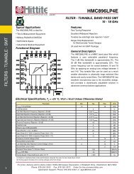
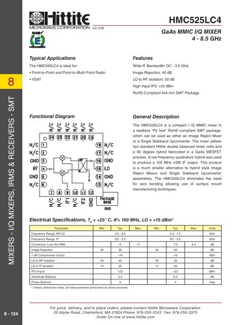
v02.1208<strong>HMC525LC4</strong>GaAs MMIC I/Q MIXER4 - 8.5 GHzQuadrature Channel Data Taken Without IF HybridIsolations-10IF Bandwidth*08MIXERS - I/Q MIXERS, IRMS & RECEIVERS - SMTISOLATION (dB)Amplitude Balance vs. LO DriveAMPLITUDE BALANCE (dB)Upconverter Performance ConversionGain vs. LO DriveCONVERSION GAIN (dB)-20-30-40-5021.510.50-0.5-1-1.50-5-10-15LO/IF1LO/RFRF/IF2-603 4 5 6 7 8 9RF FREQUENCY (GHz)LO = +13 dBmLO = +15 dBmLO = +17 dBmLO = +19 dBm-23 4 5 6 7 8 9RF FREQUENCY (GHz)LO = +13 dBmLO = +15 dBmLO = +17 dBmLO = +19 dBmLO/IF2RF/IF1RESPONSE (dB)Phase Balance vs. LO DrivePHASE BALANCE (degrees)1050-5-10-15LO = +13 dBmLO = +15 dBmLO = +17 dBmLO = +19 dBm-203 4 5 6 7 8 9RF FREQUENCY (GHz)Upconverter Performance SidebandRejection vs. LO DriveSIDEBAND REJECTION (dBc)-5-10-15-20-250.5 1 1.5 2 2.5 3 3.50-10-20-30-40-50RETURN LOSSCONVERSION GAINIF FREQUENCY (GHz)LO = +13 dBmLO = +15 dBmLO = +17 dBmLO = +19 dBm-203 4 5 6 7 8 9RF FREQUENCY (GHz)-603 4 5 6 7 8 9RF FREQUENCY (GHz)* Conversion gain data taken with external IF hybrid8 - 126For price, delivery, and to place orders, please contact <strong>Hittite</strong> <strong>Microwave</strong> <strong>Corp</strong>oration:20 Alpha Road, Chelmsford, MA 01824 Phone: 978-250-3343 Fax: 978-250-3373Order On-line at www.hittite.com
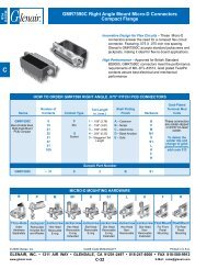
v02.1208<strong>HMC525LC4</strong>GaAs MMIC I/Q MIXER4 - 8.5 GHzEvaluation PCB8List of Materials for Evaluation PCB 109998 [1]ItemDescriptionJ1 - J2PCB Mount SMA RF Connector, SRIJ3 - J4PCB Mount SMA Connector, JohnsonU1<strong>HMC525LC4</strong>PCB [2]109996 Evaluation Board[1] Reference this number when ordering complete evaluation PCB[2] Circuit Board Material: Rogers 4350The circuit board used in the fi nal application shoulduse RF circuit design techniques. Signal lines shouldhave 50 ohm impedance while the package groundleads and exposed paddle should be connecteddirectly to the ground plane similar to that shown.A sufficient number of via holes should be used toconnect the top and bottom ground planes. Theevaluation circuit board shown is available from<strong>Hittite</strong> upon request.MIXERS - I/Q MIXERS, IRMS & RECEIVERS - SMTFor price, delivery, and to place orders, please contact <strong>Hittite</strong> <strong>Microwave</strong> <strong>Corp</strong>oration:20 Alpha Road, Chelmsford, MA 01824 Phone: 978-250-3343 Fax: 978-250-3373Order On-line at www.hittite.com8 - 129