Download Datasheet - Liberty Test Equipment
Download Datasheet - Liberty Test Equipment
Download Datasheet - Liberty Test Equipment

You also want an ePaper? Increase the reach of your titles
YUMPU automatically turns print PDFs into web optimized ePapers that Google loves.
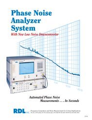
Serial Data Analyzers(9 GHz–18 GHz)Powerful Serial DataAnalysis for NextGeneration Standards
Raising the Bar for Serial Data AnalysisThe SDA 18000 serial data analyzer is a true breakthrough insignal analysis. It delivers the industry’s highest true analogbandwidth—18 GHz—as well as a combined highest samplingrate of 60 GS/s and memory of up to 150 million points availablein a real-time test instrument.Based on the industry’s most advanced digital oscilloscopeplatform, the SDA 18000 is a 4-channel real-time serial dataanalyzer that offers outstanding analysis capabilities thatnormally would require two or three different analyzers.Put these benefits to work for you:• Pristine signal integrity measurements• Accurate jitter analysis• Powerful advanced waveform analysis• Stable, repeatable resultsData Rate Configuration ChartStandard Data Rate/ Rise Time, ps min. Minimum RecommendedSymbol Rate (20%–80%) Bandwidth OscilloscopePCI Express ® 5 Gb/s 30 ps 12.5 GHz SDA 13000Gen2(Base Spec)SATA II/III Gen2 3 Gb/s 100 ps (Gen1) > 10 GHz SDA 11000Gen3 6 Gb/s 67 ps (Gen2) (SATA II) SDA 13000XAUI X2 6.25 Gb/s 30 ps ≥ 11 GHz SDA 11000Fibre Channel 8.5 8.5 Gb/s 30 ps 18 GHz SDA 18000(Fibre Channel)SAS II/SAS 6G SAS II 3 Gb/s 67 ps (Gen1) > 10 GHz SDA 18000SAS 6G 6 Gb/s 33 ps (Gen2) (SAS II/SAS 6G)FB-DIMM FBD1 4.8 Gb/s 30 ps > 10 GHz SDA 9000 or(FB-DIMM) SDA 11000FBD2 9.6 Gb/s ≥ 13 GHz SDA 13000(FB-DIMM)10 Gb Ethernet 18 GHz SDA 18000(10 Gb Ethernet)Sampling Oscilloscope Speedwith Real Time CapabilitiesThe SDA 18000 has sufficient bandwidthto allow real-time measurements of thefastest serial data standards enteringactive development today, including10 Gb/s Ethernet, and Fibre Channel 8.5.Previously, serial data measurementsand jitter analysis of these signalscould only be made with a samplingoscilloscope, a technique confined tomonitoring well-behaved signals or smallsequences of a repetitive bit pattern.Capturing the data stream in real timewith multiple points per transition edgewith digitizing resolution as low as16 ps per point allows the SDA 18000to recover the embedded clock,2
and phase lock to it, for precise jittermeasurements. Now a completebreakdown of jitter composition ispossible, even with non-repeatingpatterns or “live” data.The user can instantly switch backto the individual bit pattern or thespecific location where the maskviolation has occurred.Sampling at 60 GS/s assures excellentwaveform capture fidelity, and the150 million point memory depthallows the capture of long serial datapatterns. This is most helpful in locatingthe sources of low frequency jittermodulation or tracking spread spectrumclocked (SSC) data.SDA 13000, SDA 11000, andSDA 9000 – for Mid-speedSerial DataThe 13 GHz SDA 13000 is ideal foranalysis in systems with serial datarates up to 7 Gb/s, while the 11 GHzSDA 11000 and 9 GHz SDA 9000support rates up to 6.25 Gb/s and5 Gb/s respectively. The threeinstruments feature an architecturesupporting 2 channels at full BW.Each instrument shares the sameadvanced serial data and jitteranalysis capabilities of the SDA 18000,including Q-Scale analysis. Lowerbandwidth applications from 6 GHz to4 GHz are also well served by a numberof models in each bandwidth.New Q-Scale Analysisfor Unique InsightA remarkable innovation included withthe SDA Series is the Q-Scale analysisand plot view, a dramatic improvementthat provides much more insight intojitter than any other method.Q-Scale analysis uses an alternativemethod of breaking down jittercomponents. It also incorporatesenhancements in extrapolating thejitter histogram tails, improving theaccuracy, stability, and measurementconvergence time.The Q-Scale plot provides a visualrepresentation of jitter breakdown,which is much more intuitive thana traditional bathtub curve.3
A Total Solution for the Fastest Serial Data RatesThe LeCroy SDA 18000/13000/11000/9000 integrates all the keymeasurement and analysis toolsinto one device.• Serial data measurements upto 10 Gb/s• Supports testing of next generationserial data standards:– 10 Gb/s Ethernet– 8.5 Gb/s Fibre Channel– 6 Gb/s SATA III / 3 Gb/s SATA II– 6 Gb/s SAS– 4.8 Gb/s FB-DIMM– 6.25 Gb/s double XAUI• WiMedia UWB Tx testing upthrough band group 5• LeCroy 8b/10b serial decode optionwith powerful search capabilityenables captured waveforms tobe searched for user-definedsequences of symbols. Multi-laneanalysis decodes up to four simultaneouslycaptured lanes.• Capture of up to 12 million UnitIntervals (UI) in a single acquisitionallows measurements of importantlow-frequency effects, such asspread spectrum clocking andswitching power supply noise.• LeCroy’s Digital Signal Processing(DSP) technology brings uniformityin frequency and phase response,resulting in dependable eye patternrepresentation. LeCroy uses DSPfor equalization compensation, notBW extension.• Configurable software PLL for anystandard or custom requirement.A. Eye Patterns Show MaskViolations to the Bit• Eye pattern measurement on up to12 million consecutive bits capturespatterns of PRBS > 2 23 –1.• Consecutive-bit eye pattern analysisallows for the measurement of thewave shapes of individual bitsthat violate the compliance mask(violation location).• Fast update rate.• Very low noise floor jitter(less than 350 fs rms, typical).B. Jitter Trend• Time domain view of jitter displaystransient jitter events that can bemissed by histogram approaches.• Clearly shows any non-stationaryjitter behavior.X-Stream ArchitectureAn innovative and highly efficient softwarearchitecture optimized for complexprocessing of large waveforms, X-Streamhas these industry exclusive features:Fastest Processing Speed: X-Streampipelines data at 10 Gb/s into acquisitionmemory. It is then packetized intosegments small enough to allow theremaining processing to take place in theC. Jitter Bathtub• The bathtub curve is extrapolatedfrom a TIE histogram rather than froma jitter model. This produces resultsthat correlate better with those froma bit error rate tester (BERT).• Presents jitter as a function ofbit error rate.• Predicts maximum Bit Error Rate(BER) performance of system.D. Histogram with Q-Scale• Display of measured jitter histogramclearly shows any unusual jitterdistributions such as bi-modal ornon-Gaussian tails.• By simply viewing the jitter breakdown(Rj, Dj), the raw data viewshows jitter behavior that can be lost.• This unprocessed display gives a highdegree of confidence in the accuracy ofthe jitter breakdown and bathtub curve.processor cache memory—eliminatingthe need for constant external memory“fetches.” This dramatically speeds upcomplex waveform processing.Single Microsoft Windows ® Application: InX-Stream, all of the oscilloscope operation,acquisition, and analysis take placein one single application running underWindows XP Professional. Data transferwithin this application is optimized for4
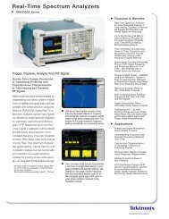
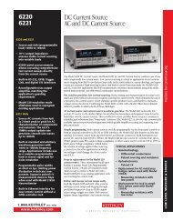
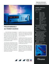
The SDA 18000 Features:1. 18 GHz analogbandwidth2. 19 ps (typ. 20–80%)rise timeAB43. Up to 150 Mptsof waveformacquisition memory234. One-touch to SerialData Analysis5. Sampling rates up to60 GS/s with deepestmemory6. Wavepilot – provideseasy access to powerfulsignal analysiscapabilities.7. Front panel USB 2.0C1D567large waveform processing. Otheroscilloscopes acquire the waveform ina basic scope application, and pass thedata to other applications for serial dataor jitter analysis. This less efficient designcan limit the user to seeing either theeye pattern or the data waveform or thejitter analysis—but not all simultaneously.Embedded user applications: OnlyX-Stream allows users to embed theirown processing application within thedata stream and display the results—inreal time. For example, users could writea routine that emulates the receiverequalization filter and insert it within thedata stream. They could then see theeye pattern as the receiver does. Theycould also run a complete jitter breakdownanalysis on the filter data—in realtime with live data. Compare this withrunning a filter routine off-line in a laptopwith static acquired waveform data.Application scripts can be written inMathcad, ® MATLAB, ® VBScript, and evenExcel. ® An optional Processing WebEditor allows users to quickly combinetheir application script with built-in mathfunctions in a simple to understandgraphical object representation.5
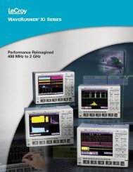
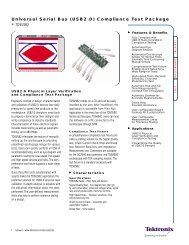
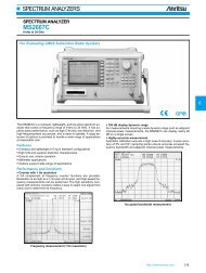
New Q-Scale—See Jitter Components AccuratelyFirst introduced in real-time serial data analyzers by LeCroy, the new Q-Scale view showsa graphical representation of key jitter components. It is a powerful tool for the engineertroubleshooting the source of jitter in circuits.In brief, Q-Scale analysis depicts aGaussian distribution as a straight line.There are two fundamental benefitsof using Q-Scale:1. When placed on top of the referenceline, you can instantly judge howGaussian the distribution is. Thisis much easier than trying to lookat the sides of a bathtub curve.2. Greatly improved stability of theRandom Jitter (Rj) component.Because the Rj component is heavilyweighted to form the Tj, the Total Jitternumber is also much more repeatable.Interpreting the Q-ScaleAs with any jitter histogram, thewidth indicates the amount of jitter.The slope of the grey lines decreaseswith increasing random jitter.The alignment of the red lines withthe grey reference lines indicates howclose to pure Gaussian the distributionon the corresponding face is. Notethat it is possible and common forthe two faces of the histogram to benonsymmetrical, and even representdifferent amounts of jitter relative tothe ideal edge placement.The bottom tails of the red lines curveinward toward the center when thereis a bounded component present.Likely sources of this jitter would becross talk and power supply noise.The distance between the dottedlines in the center is the deterministic(effective Dj) component, in the61. Linearity Reveals the Sourceof Random JitterWhen red line lies on grey reference,the face has a Gaussian distribution.• Bottom curves outward = more Rj• Bottom curves inward = morebounded2. Total Jitter Population at YourFinger TipsBase of the histogram is total jitterinterval at selected BER (shown asdotted lines).correct time scale. There is no separationin these lines when the Dj is zero,indicating pure random jitter.Three parameters are used to fit thetail of the histogram—Sigma, Mean,and Population. The Rho factor indicatesthe closeness of the data fit tothe extrapolated model necessary3. Precise Intuitive Calculation of RjSlope of grey line decreases within creasing Rj.4. Directly View Dj MagnitudeIntersection of the grey referencelines with the top of the grid representsthe deterministic component in time(Effective Dj). Displayed as dottedvertical lines: Sigma value = RandomJitter Rho-fitting coefficient (qualityof model fit)to extend the histogram to the selectedBER. A value of 1.0 would indicatea perfect fit to a single Gaussiandis tribution. Rho is the amount ofthe distribution of the histogram fitinto the extrapolated tail. Essentially,this number represents a figure ofmerit for the measurement quality.
Eye Doctor – Tools for Next Generation Serial Data AnalysisAs the symbol rates of systems haveincreased, the measurement challengeshave also and with the adoption ofreceiver equalization, traditional jitterand noise measurements are becominginadequate for determining interoperability.Equalizer emulation simulates the signal as viewed within the receiver.The component can automatically determine the optimum weightingcoefficients for both FFE and DFE with the number of taps for eachselected by the user. Coefficients can also be entered directly. The fulljitter analysis capability of the SDA is available on the equalized signal.Eye Doctor is a DSO-based instrumentationand simulation system whichaddresses these measurement challengesand is a dramatic leap in interoperabilityand compliance testing capability.Eye Doctor provides the tools to undoor compensate many common formsof distortion thereby increasing signalto noise, opening eyes, increasing risetime, reducing jitter restoring lost bandwidthand improving waveform fidelity.Measured Signal atTransmitterVirtually Probed Signalat ReceiverEqualized SignalVirtual Probing simulates signals from any point within the system using a singlemeasured waveform. The virtual probe shown here is co-simulating a backplanewhich closes the eye. The equalizer corrects the distortion caused by the backplanewhich opens the eye. The Processing Web Editor is used to connect theequalizer and Virtual Probing elements in an intuitive signal flow diagram layout.7
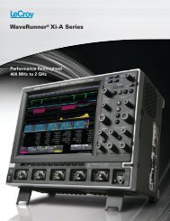
Advanced Analysis ToolsExtensive Capabilities Deliver Exceptional PerformanceAlthough serial data compliance testing is widely available,analyzers that easily discover the reason for failing a compliancetest are not. Only LeCroy SDA Series offers the class-leadingserial data and jitter analysis toolset to help understand thecauses behind the failure. With them, you can quickly identifythe nature of the jitter and isolate the source of the problem.To ensure your jitter measurements The SDA Series contains the mostare comprehensive and precise, the analysis tools and jitter measurementSDA Series oscilloscope uses the methods available today. Combined withstandard industry breakdown for jitter, X-Stream, which provides the fastestThis means measurements areanalysis in this class of instrument, andcomplete and correct. This level of up to 18 GHz of bandwidth, no other tooljitter detail is unprecedented. By can offer more utility for the engineercapturing jitter detail this accurately, designing high-speed serial data systems.jitter problems can be characterized Here are just a few of the unique capabilitiesin the LeCroy SDA and resolved quickly and efficiently.Series.ISI PlotThe ISI plot displays data dependentjitter contributions to the eye patternfor the second-to-last bit of a bitlength, set from 3 to 10. This plotmeasures data dependent jitterwithout the need for a repeatingbit pattern.Jitter WizardThis feature automatically selectsall of the critical instrument settings,ensuring the highest accuracy andrepeatability.• Sampling rate, level, bit rate, andpattern length are automaticallydetected.Edge-to-Edge JitterIn this mode, timing is measuredon data transitions relative to oneanother in the same way as a TIA.• Measurements can be displayeddirectly or compensated to correlatewith phase jitter measurements.• Tj, Rj, and Dj measurements can bemade at specific UI spacings or forall spacings in the data stream.Filtered JitterThe SDA Series oscilloscope offers afiltered jitter mode to support ITU-Tand SONET measurements.• Band-pass filter with selectableupper and lower cutoff frequenciessupplied.ISI Plot – Isolate Specific Bit PatternsAverages the contribution to the eye pattern from samples with the same combinationof bit values preceding and following the plotted UI.8
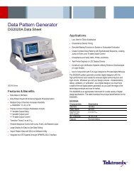
Spread Spectrum ClockLeCroy’s unique long acquisitionmemory and fast sample rate are idealfor seeing fine details in data transmittedwith Spread Spectrum Clocks (SSC).SSC is becoming popular due to itslower noise contribution. The modulationfrequency used is low, typically 33 kHz.With 150 Mpts of waveform memory,the SDA 18000 can capture over 72entire cycles of SSC while samplingat its maximum rate of 60 GS/s.Mask Violation Locator andMulti-EyeMask failures are identified by contrastingcolor spots on the eye pattern,which appear anywhere the dataintersects the mask template. Usingthe Mask Violation Locator tool, userscan call up the actual stored bit streamwaveform at the point in time of theinitial failure. The actual bit sequenceis also identified, pointing out any ISIproblems. Cursor controls allow theuser to instantly jump to the nextviolation, or any other that occurredin the stored pattern.The mask violation locator workseffectively on single and multiple eyemasks. Multi-Eye can be used whenevertwo valid eye patterns occur inthe same data channel, such as differenttransmit and receive waveformsin bi-directional channels (FSB) andtransition/non-transition bit applications,as found in PCI Express. Independentmeasurements such as rise and falltime, eye amplitude, etc., can be madein each eye.See multiple cycles of spread spectrum clocking.Observe bit sequences that cause mask violations.9
Next Generation Physical Layer Compliance <strong>Test</strong>sCompliance <strong>Test</strong>ingThe transfer of digital data signals is increasingly movingto serial format. Serial data has several advantages overparallel such as scalability, speed and compactness. Atthe same time, these new serial data standards requirespecialized measurements and compliance testing procedureswhich add complexity to their design. Spanning thecomplete device development cycle, design engineers canfocus on systematic, step-by-step functional device developmenttasks by selecting tests from the checklist. The useof LeCroy’s compliance test software in conjunction withthe deep memory and powerful analysis library of the SDAinstrument family greatly simplifies the verification process.Transition and non-transition eye diagrams for PCI Express.SATA compliance test maximum voltage check.Configure and decode up to 4 channels.Spectogram of a UWB signal hopping over three frequency bandsof a band group.10
Differential Probing SolutionsThe DA18000 DifferentialAmplifierThe DA18000 Differential Amplifieris a very high bandwidth DC coupleddifferential amplifier with a true 100 Ωbalanced input. It features high commonmode rejection, low noise, and isdesigned to be used exclusively withthe SDA 18000 Serial Data Analyzer.The amplifier has unity gain, to maximizethe signal to noise performancewhen used with the lower amplitudesignal voltages common in higherdata rate systems.The DA18000 is supplied with a shortpair of input cables which are matchedto an electrical propagation length of2.5 ps. Use of the DA18000 withthese cables eliminates the need todeskew and calibrate input channelsfor differential match, a problemSpecificationInput ConfigurationInput ConnectorFrequency Response, SystemRise time, 20%–80%, SystemRise time, 20%-80%, Probe Onlyencountered when acquiring differentialsignals with two oscilloscope channelsconnected with long cables.The DA18000 differential amplifierutilizes third generation digital responseequalization, the same calibrationmethod used in LeCroy’s award winninghigh bandwidth probes. This providesthe most accurate magnitude and phaseresponse, assuring the high fidelity eyepattern measurements.ValueTrue Differential, 100 Ω Balanced2.92 mmDC–18 GHz, Typical< 24 ps, Typical< 19 psVoltage Gain X 1Voltage Gain AccuracyMax. Offset Voltage, RTINoise, SystemMaximum Input – Differentialwith ÷2 AttenuatorsMaximum Input – Common Modewith ÷2 AttenuatorsCommon Mode Resistance, DC2%, (20–30 ºC)< 5 mV1 mV rms, Typical±400 mV (800 mV p-p)±800 mV (1.6 V p-p)±10 V7 V rms25 kΩD13000PS/D11000PSDifferential Probe SystemThe D13000PS/D11000PS extendsthe full signal acquisition performanceof the SDA 13000, SDA 11000 andSDA 9000 to the probe tips. With13/11 GHz system bandwidth, theprobe enables direct measurementof high-speed serial data streamsup to 6.25 Gb/s.When used to acquire input signalsfor the SDA 13000, SDA 11000,SDA 9000, or SDA 18000, theD13000PS/D11000PS providesunprecedented waveform fidelity,even with signals at higher serial datarates. Each probe utilizes third generationresponse compensation calibration,the most advanced in use today,to provide optimal system response.The D13000PS/D11000PS providesboth direct Solder-In and cabled SMAconnectorinterconnect lead assemblies.The D13000PS also provides SMPcables for additional cabling options.Each interconnect lead comes with adedicated probe amplifier module thathas calibration data optimized for therespective lead. This eliminates theperformance compromise of using asingle calibration for multiple lead types.Included with the DA18000:Electrically matched input cables (2), ÷2 precision attenuators (2),ESD dissipating wrist strap, Instruction Manual, certificate of traceablecalibration, soft accessory case.11
SpecificationsSDA 18000 SDA 13000 SDA 11000 SDA 900018 GHz/Ch 11 GHz/Ch 6 GHz/Ch 13 GHz/Ch 6 GHz/Ch 11 GHz/Ch 6 GHz/Ch 9 GHz/Ch 6 GHz/ChVertical System Mode Mode Mode Mode Mode Mode Mode Mode ModeAnalog Bandwidth @ 50 Ω (-3 dB)Rise Time (Typical, 10–90%)Rise Time (Typical, 20–80%)Input ChannelsBandwidth LimitersInput ImpedanceInput CouplingMaximum Input VoltageVertical ResolutionSensitivityDC Gain AccuracyOffset RangeOffset Accuracy18 GHz 11 GHz 6 GHz 13 GHz 6 GHz 11 GHz 6 GHz 9 GHz 6 GHz27 ps 40 ps 75 ps 35 ps 75 ps 40 ps 75 ps 49 ps 75 ps19 ps 28 ps 25 ps 28 ps1 1 4, 2, or 1 2 or 1 4 or 2 2 or 1 4 or 2 2 or 1 4 or 220 MHz, 20 MHz, 20 MHz, 20 MHz,Full BW only 200 MHz, Full BW 200 MHz, Full BW 200 MHz, Full BW 200 MHz,1 GHz, 3 GHz, only 1GHz, 3 GHz, only 1 GHz, 3 GHz, only 1 GHz, 3 GHz,4 GHz 4 GHz 4 GHz 4 GHz50 Ω ±2.0%DC, GND±4 V peak8 bits; up to 11 bits with enhanced resolution (ERES)2 mV–1 V/div(< 10 mV/divthrough zoom)±1.5% of full scale±750 mV @2 mV–141 mV/div±4 V @141 mV–1 V/div±(1.5% of full scale +1.5% of offset value +2 mV)2 mV–1 V/div 2 mV–1 V/div 2 mV–1 V/div 2 mV–1 V/div 2 mV–1 V/div 2 mV–1 V/div 2 mV–1 V/div(fully variable, (
StandardAdvanced Serial Data Analysis ToolsEye Diagrambit ratepattern detectTx densitymask test with violation locatoreye amplitudeClock Recoverystandard PLL settings(FC GOLDEN, PCI Express,DVI, Custom)custom filter settingsJitter Analysisjitter wizardedge to reference (data to clock)edge to edge (data to data)conventionaleffectiveMJSQbasic (Tj, Rj, Dj)Dj breakdown (DDj, Pj, DCD)advanced (peak-peak and rms)TIE jitterISI plot with bit sequence trackingeye timingeye crossingextinction ratioaverage powernumber of polesnatural frequencydamping factorsynchronous N-cycle with bitpattern displaybathtub curvejitter histogramfiltered jitterperiodic jitter (Pj) withpeak frequency listingTIE clock jitterperiod jitterhalf-period jittercycle-cycle jitterMath ToolsDisplay up to four math function traces (F1 – F4). The easy-to-use graphical interfacesimplifies setup of up to two operations on each function trace, and function traces canbe chained together to perform math-on-math.absolute valueAuto-correlation functionaverage (summed)average (continuous)cubic interpolationfunctionderivativedeskew (resample)difference (–)enhanced resolution(to 11 bits vertical)envelopeexp (base e)exp (base 10)Measure ToolsDisplays any 8 parameters together with statistics, including their average, high, low,and standard deviations. Histicons provide a fast, dynamic view of parameters andwave shape characteristics.amplitudeareabasecyclesdelayΔ delayduty cycledurationfalltime (90–10%,80–20% @level)frequencyfft (power spectrum,magnitude, phase,up to 25 Mpts)floorhistogram of2 billion eventsintegralinvert (negate)log (base e)log (base 10)parameter math(+,-,*,/ of twodifferent parameters)product (x)firsthistogramparameterslastlevel@ xmaximummeanmedianminimumnarrowband powermeasurementsnumber of points+overshoot–overshootpeak-to-peakperiodphaserisetime (10–90%,20–80% @level)rmsstd. deviationtopratio (/)reciprocalrescale (with units)roof(sinx)/xsparse functionsquaresquare rootsum (+)track graphstrend (datalog) of1 million eventszoom (identity)widthtime@minimum(min.)time@maximum(max.)Δ time@levelΔ time@level fromtriggerx@maxx@minPass/Fail <strong>Test</strong>ingSimultaneously test multiple parameters against selectable parameter limits orpre-defined masks. Pass or fail conditions can initiate actions, including documentto local or networked files, e-mail the image of the failure, save waveforms, outputa pulse via the the front panel auxiliary BNC output, or (with the GPIB option) senda GPIB SRQ.8B/10B Protocol DecodingSimultaneously translates up to 4 lanes of 8B/10B encoded Serial Data waveformsinto symbol views to allow easier troubleshooting. This allows the user to quicklycorrelate protocol events with the physical serial data waveform. The decoderoperates with 8B/10B encoded data at rates up to 6.25 Gb/s.OptionalAdvanced Customization Package (XDEV)This package provides a set of tools to modify the oscilloscope and customize it tomeet your unique needs. Additional capability provided by XDEV includes:• Creation of your own measurement parameter or math function, using third partysoftware packages, and display of the result in the oscilloscope. Supported thirdparty software packages include:– VBScript– MATLAB– Excel– Mathcad• CustomDSO – create your own user interface in a oscilloscope dialog box.• Adding macro of keys to run VBScript files• Support of plug-insSerial Data Compliance Packages• QPHY-ENET – Ethernet Application Software Package• QPHY-USB – USB Application Software Package• SDA-SATA – SATA Gen1/Gen2 Solution Analysis Software Package• SDA-FBDIMM – FB-DIMM Solution Analysis Software Package• SDA-HDMI – HDMI Compliance <strong>Test</strong> Software Package• SDA-PCIE-G2 – PCI Express Development and Compliance Software forGen1 and Gen2• SDA-SAS – SAS I/II Solution Analysis Compliance Software Package• SDA-UWB – UWB <strong>Test</strong> Solution Software Package15
Ordering InformationDescriptionProduct CodeSerial Data Analyzers4 Ch; 18 GHz Serial Data Analyzer; 18 GHz, 60 GS/s SDA 1800060 Mpts on 1 Ch, 6 GHz, 20 GS/s 20 Mpts/Ch on 4 Ch4 Ch; 13/6 GHz Serial Data Analyzer; 13 GHz, 40 GS/s SDA 1300040 Mpts on 2 Ch; 6 GHz, 20 GS/s 20 Mpts on 4 Ch4 Ch; 11/6 GHz Serial Data Analyzer; 11 GHz, 40 GS/s SDA 1100040 Mpts on 2 Ch; 6 GHz, 20 GS/s 20 Mpts on 4 Ch4 Ch; 9 GHz Serial Data Analyzer; 9 GHz 40 GS/s 40 Mpts/Ch SDA 9000on 2 Ch; 6 GHz, 20 GS/s 20 Mpts/Ch on 4 ChIncluded with Standard ConfigurationProLink Adapter, Type K; 1 each (SDA 18000 only)ProLink Adapter, SMA; 4 each (3 each with SDA 18000)ProLink Adapter BNC; 2 eachPrinted Getting Started Manual, Operator’s ManualCD-ROMs containing Operator’s Manual, Remote Control Manual,Automation Manual, and Software Options ManualCD-ROMs containing Utility Software andNorton Antivirus Software (1 year subscription)CD-ROM DriveOptical 3-button Wheel Mouse-USBStandard Ports; 10/100Base-T Ethernet, Parallel,SVGA Video Output, PowerMac G4/QS USB 2.0Power Cable (for the country ordered from)Protective Front CoverStandard Commercial Calibration and Performance Certificate3-Year WarrantyLPA-KLPA-SMALPA-BNCMemory OptionsFor SDA 18000:150 Mpts/18 GHz, 100 Mpts/11 GHz, 50 Mpts/4 Ch SDA18-XLFor SDA 13000:100 Mpts/13 GHz, 50 Mpts/4 Ch SDA13-XLFor SDA 11000:100 Mpts/11 GHz, 50 Mpts/4 Ch SDA11-XLFor SDA 9000:100 Mpts/9 GHz, 50 Mpts/4 Ch SDA9-XLSoftware OptionsCompliance Software OptionsQualiPHY Automated <strong>Test</strong> and Reporting Software PackageEthernet Application Software PackageUSB Application Software PackageFB-DIMM Solution Analysis Compliance Software Package(SDA 13000 / SDA 11000 / SDA 9000 only)HDMI Compliance <strong>Test</strong> Software PackagePCI Express Development and Compliance Softwarefor Gen1 and Gen2SAS Compliance Software PackageSATA Gen1/Gen2 Solution Analysis Software PackageUWB <strong>Test</strong> Solution Software PackageApplication Specific <strong>Test</strong> and Analysis Software OptionsAdvanced Optical Recording Measurement Software PackageDisk Drive Measurements Software Package*TF-ENET-B required. **TF-USB-B required.QPHYQPHY-ENET*QPHY-USB**SDA-FBDIMMSDA-HDMISDA-PCIE-G2SDA-SASSDA-SATASDA-UWBAORMDDM21-800-5-LeCroywww.lecroy.comLocal sales offices are located throughout the world.To find the most convenient one visit www.lecroy.com© 2007 by LeCroy Corporation. All rights reserved. Specifications, prices, availability and deliverysubject to change without notice. Product or brand names are trademarks or requested trademarksof their respective holders.DescriptionSoftware Options (cont’d)Advanced Math and WaveShape Analysis Software OptionsDigital Filter Software PackageAdvanced Customization Software PackageProcessing Web Editor Software PackageEye Doctor (Virtual probe and equalizer emulation bundle)Virtual ProbeEqualizer EmulationProduct CodeDFP2XDEVXWEBEYEDREYEDR-VPEYEDR-EQHardware and Software Option32 Digital Oscilloscope Mixed Signal Option MS-32-DSAHardware Options and Accessories2 x 36 inch SMA to SMA Cable ENET-2CAB-SMA0362 x 18 inch SMA to SMA Cable ENET-2CAB-SMA0182 x BNC to SMA Adapter ENET-2ADA-BNCSMA40 GHz Trigger Prescaler SDA-TPS1 MΩ Adapter includes PP005A Passive Probe AP-1MIEEE-488 GPIB Control InterfaceGPIB-1Dual Monitor DisplayDMD-1Keyboard, USBKYBD-1ProLink-to-BNC Adapter; 1 eachLPA-BNCKit of 4 ProLink BNC Adapters with CaseLPA-BNC-KITProLink-to-SMA AdapterLPA-SMAKit of 4 SMA ProLink Adapters with CaseLPA-SMA-KITProLink-to-Type ‘K’ adapter; 1 eachLPA-KOscilloscope Cart with Additional Shelf and DrawerOC1024Oscilloscope CartOC1021Removable Hard Drive PackageWM-RHDAdditional Removable Hard DriveWM-RHD-02Hard Shell Transit CaseSDA11-TC1Compliance <strong>Test</strong> FixturesHDMI <strong>Test</strong> Fixture Set (TPA-P-SE, TPA-P-DI)10/100/1000Base-T Compliance <strong>Test</strong> FixtureUSB 2.0 <strong>Test</strong>ing Compliance <strong>Test</strong> FixtureTelecom Adapter Kit 100 Ω Bal., 120 Ω Bal., 75 Ω Unbal.Serial ATA <strong>Test</strong> Fixture (Includes Pair of SMA Cables)*Includes ENET-2CAB-SMA018.TF-HDMITF-ENET-B*TF-USB-BTF-ETTF-SATAProbe Options and Probe Accessories18 GHz Differential Amplifier (SDA 18000 only) DA1800013 GHz Differential Probe System D13000PS11 GHz Differential Probe System D11000PSWaveLink 7.5 GHz, Differential Probe Adjustable Tip ModuleD600A-AT*WaveLink 7 GHz, Differential Probe Small Tip ModuleD600ST*WaveLink 4 GHz, 5 V Differential Probe Small Tip ModuleD350ST*WaveLink 6 GHz, Differential Positioner Mounted Tip Probe Module D500PT*WaveLink ProLink Probe BodyWL6001 GHz Active Differential Probe (÷1, ÷10, ÷20) AP0347.5 GHz Low Capacitance Passive Probe (÷10, 1 kΩ; ÷20, 500 Ω) PP0662.5 GHz 0.7 pF Active Probe (÷10), Small Form Factor HFP2500Probe Deskew and Calibration <strong>Test</strong> FixtureTF-DSQCascade Microtech EZ-Probe PositionerEZ PROBE*For a complete probe, order a WL600 Probe Body with the Probe Tip Module.Customer ServiceLeCroy oscilloscopes are designed, built, and tested to ensure high reliability. In theunlikely event you experience difficulties, our digital oscilloscopes are fully warrantedfor three years, and LeCroy probes are warranted for one year.This warranty includes: • No charge for return shipping • Long-term 7-year support• Upgrade to latest software at no chargeSDA18KDSrevB_31Oct075K LG