NTE1632 Integrated Circuit Vertical/Horizontal Sync Separator
NTE1632 Integrated Circuit Vertical/Horizontal Sync Separator
NTE1632 Integrated Circuit Vertical/Horizontal Sync Separator

Create successful ePaper yourself
Turn your PDF publications into a flip-book with our unique Google optimized e-Paper software.
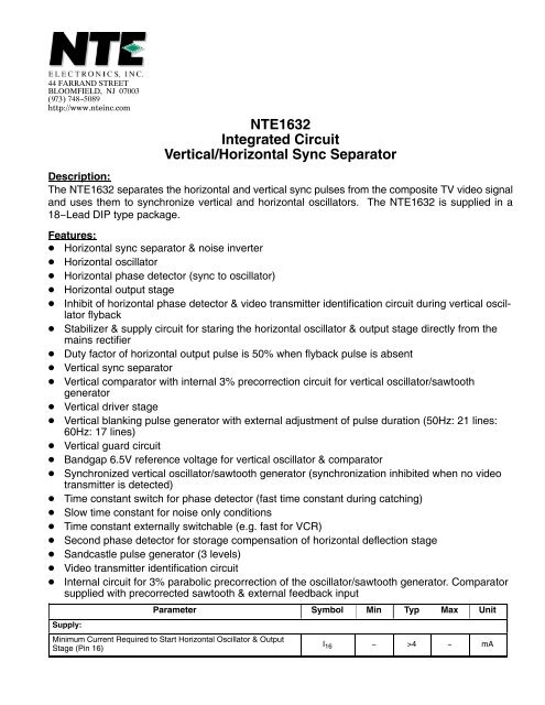
<strong>NTE1632</strong><strong>Integrated</strong> <strong>Circuit</strong><strong>Vertical</strong>/<strong>Horizontal</strong> <strong>Sync</strong> <strong>Separator</strong>Description:The <strong>NTE1632</strong> separates the horizontal and vertical sync pulses from the composite TV video signaland uses them to synchronize vertical and horizontal oscillators. The <strong>NTE1632</strong> is supplied in a18−Lead DIP type package.Features: <strong>Horizontal</strong> sync separator & noise inverter <strong>Horizontal</strong> oscillator <strong>Horizontal</strong> phase detector (sync to oscillator) <strong>Horizontal</strong> output stage Inhibit of horizontal phase detector & video transmitter identification circuit during vertical oscillatorflyback Stabilizer & supply circuit for staring the horizontal oscillator & output stage directly from themains rectifier Duty factor of horizontal output pulse is 50% when flyback pulse is absent <strong>Vertical</strong> sync separator <strong>Vertical</strong> comparator with internal 3% precorrection circuit for vertical oscillator/sawtoothgenerator <strong>Vertical</strong> driver stage <strong>Vertical</strong> blanking pulse generator with external adjustment of pulse duration (50Hz: 21 lines:60Hz: 17 lines) <strong>Vertical</strong> guard circuit Bandgap 6.5V reference voltage for vertical oscillator & comparator <strong>Sync</strong>hronized vertical oscillator/sawtooth generator (synchronization inhibited when no videotransmitter is detected) Time constant switch for phase detector (fast time constant during catching) Slow time constant for noise only conditions Time constant externally switchable (e.g. fast for VCR) Second phase detector for storage compensation of horizontal deflection stage Sandcastle pulse generator (3 levels) Video transmitter identification circuit Internal circuit for 3% parabolic precorrection of the oscillator/sawtooth generator. Comparatorsupplied with precorrected sawtooth & external feedback inputSupply:Parameter Symbol Min Typ Max UnitMinimum Current Required to Start <strong>Horizontal</strong> Oscillator & OutputStage (Pin 16)I 16 − >4 − mA
Main Supply Voltage (Pin 10)ParameterSymbolMinTypMaxUnitV P =V 10−9− 12 − VSupply Current I P = I 10 − 55 − mAInput Signals:<strong>Sync</strong> Pulse Input Voltage(Peak−to−Peak Value; Negative Going)Output Signals:V 5−9(p−p)0.15 to 1V<strong>Horizontal</strong> Output Pulse (Open Collector) at I 11 = 40mA V 11−9 − 4 − VRatings:Start Current (Pin 16) I 16 − − 8 mASupply Voltage (Pin 10) V P = V 10−9 − − 13.2 VTotal Power Dissipation T tot − − 1.1 WStorage Temperature Range T stg −55 to +150°COperating Ambient Temperature Range T amb −25 to +65°CThermal Resistance:From Junction to Ambient in Free Air R th J−A − 50 − kWCharacteristics: I 16 = 5mA: V p = 12V: T amb = 25°C (unless otherwise indicated)Supply:Supply Current at Pin 16 I 16 4 to 8 mAStabilized Supply Voltage (Pin 16) V 16−9 − 8.7 − VSupply Current (Pin 10) I 10−
Second Control Loop:Parameter(<strong>Horizontal</strong> Output to Flyback: Pin 14)SymbolControl Sensitivity; Static (Note 2) ∆t d /∆t o − 400 − µs/µsControl Range t d 1 to 50 µsControlled EdgePhase Adjustment (Via 2nd Control Loop; Pin 14)NegativeControl Sensitivity − 25 − µA/µsMaximum Permissible Control Current ±I 14 −
ParameterSymbol Min Typ Max UnitCoincidence Detector: Video Transmitter ID <strong>Circuit</strong>; Time Constant Switches (Pin 18) (See Fig 2)Detector Output Current ±I 18 − 300 − µAVoltage During Noise (Note 4) V 18−9 − 0.3 − VVoltage Level for In−<strong>Sync</strong> Condition V 18−9 − 7.5 − VSwitching Level Slow to Fast V 18−9 3.2 to 3.8V− 3.5 −Switching Level Must Function Active; φ 1 Fast to Slow V ± 8−9 − 1.21.0 to 1.4−<strong>Vertical</strong> Period Counter 3 periods fast V 18−9 0.08 to 0.16− 0.12 −VVSwitching Level Slow to Fast (Locking) Mute FunctionInactiveV 18−9 1.5 to 1.9− 1.7 −VSwitching Level Fast to Slow (Locking) V 18−9 4.7 to 5.3− 5.0 −VSwitching Level for VCR (Fast Time Constant)Without Mute FunctionV 18−9 8.2 to 9.0− 8.6 −VVideo Transmitter ID Output (Pin 13)Output Voltage Active (No <strong>Sync</strong>) at I 13 = 1mA V 13−9 − 11 −− >10 −VOutput Voltage Active (No <strong>Sync</strong>) at I 13 = 5mA V 13−9 − >7 − VOutput Voltage Inactive V 13−9 − 0.1 −−
ParameterSymbol Min Typ MaxInput Voltage; DC Level V 2−9 4.0 to 4.8− 4.4 −UnitVAC level (Peak−to−Peak) V 2−9(p−p) − 1.6 − VInput Current at V 2−9 = 6V I 2 −