O36502 Targon PFT.pdf - Osteosyntese
O36502 Targon PFT.pdf - Osteosyntese
O36502 Targon PFT.pdf - Osteosyntese

Create successful ePaper yourself
Turn your PDF publications into a flip-book with our unique Google optimized e-Paper software.
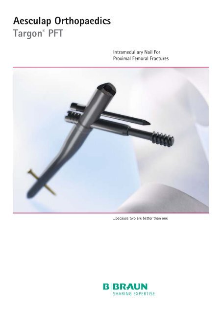
Aesculap Orthopaedics<strong>Targon</strong> ® <strong>PFT</strong>Intramedullary Nail ForProximal Femoral Fractures...because two are better than one
<strong>Targon</strong> ® <strong>PFT</strong>Priv. Doz. Dr. H.-W. Stedtfeld,Centre for Trauma Surgery,Nuremberg, GermanyDear colleagues,For 10 years now, the clinical results of treating the various typesof trochanteric fractures with the <strong>Targon</strong> ® PF have been excellent.These results have been published and presented in numerous countries.Complication rates have sometimes been sensationally low.The optimum telescopic property inherent in this combination ofa lag screw with a nail has proven its worth. This is manifested bya very low cut-out rate. System performance has also profited fromhaving medialized the telescoping action, since this avoids secondaryprotrusion of the implant into the peritrochanteric soft tissue.This occurs regularly with other systems during impaction of thefractured bone and quite often results in revision surgery. Nevertheless,there were indications for further improvement of thesystem with even better reduction of the complication rate. Thisdevelopment has resulted in the present <strong>Targon</strong> ® <strong>PFT</strong> system.The new thread of the lag screw represents yet another significantmodification. As has been demonstrated in experimentalmodels, this ensures a better grip even in osteoporitic bone, whileat the same time lowering the risk of penetration (for instance, asin cut-out).Another major improvement has been to simplify and color-codethe instruments. A unique patented adapter system permits mountingof the targeting device irrespective of the CCD angle: there is justone targeting device for all angles.These then are the most important but by no means the onlymodifications. The <strong>Targon</strong> ® PF-Nail, of course, still retains all of itspresent essential features.The most important modification, which is also reflected by the newname of the system, has been to merge both sleeve and lag screwinto what is known as the "TeleScrew" (T).This virtually rules out any uncontrolled proximal migration, whichmight take place if the sleeve is too short (an extremely rare complicationto date).H.-W. Stedtfeld, April 20092
System Advantages ImplantsTeleScrewDynamic sliding action through telescoping cantileverLinked lag screw in thesleeve❚ More efficient implantationExpanded maximumsliding range❚ Deeper manual extension ofthe TeleScrew for optimum subcorticalplacement of the screwOptimized lag screw thread❚ Pan-head screw with a cylindrical core❚ Rounded cutting edges, self-tapping both forinsertion and removal❚ Prevents perforation of the screw❚ Larger contact zone with the bone❚ Better fixation of the screw in the osteoporoticbone❚ Less cut-out of the thread❚ Deeper manual screwing of the TeleScrewspares the interfaceeIntegrated distraction stop❚ Stops the lag screw from migratingproximally4
System Advantages ImplantsReinforced design of the distal sleeve❚ Longer and more flattened jamming thread❚ Increased stability of the composite systemLonger lag screw guidancein the sleeve❚ Improved telescoping action❚ Minimum risk of jammingStandard nail5
Antirotation PinBiaxial stabilization of the fracture without the risk of rotationAntirotation pin with lateral reinforcement❚ Increased stability of the implant❚ Less risk during removalStandard NailNail with proximal reinforcement❚ Less risk of fracture at the zone with the highestloadingBetter elasticity through longitudinalslots❚ Less risk of fracture at the nail boundaryLong NailCannulated for easier passage of the nailacross the fracture zoneLong nail with thicker wall for pathologicfracturesflattened ontwo sidesLong nailflattened ontwo sidesShort NailShort nailNail length 175 mm❚ Implant best compatible with smallskeletal systems6
System Advantages InstrumentsTorque ScrewdriverPreset torque during insertion ofboth TeleScrew and antirotationpin❚ Prevents excessive jamming of theimplants❚ Facilitates implant removalGraduated Drill BitSelf-centering graduated drill bit❚ Less operating stepsDepth stop for graduated drill bit in the nail❚ Safe drilling to the predefined length of the TeleScrew7
Contoured ReamerRadiopaque marking on thecontoured reamer❚ Facilitates intraoperative assessment ofthe neck shaft (CCD) angle❚ Helps precise positioning of the TeleScrew8
System Advantages InstrumentsTargeting DeviceNew targeting device❚ Optimized geometry of the bow permits smaller incisionsand thus less invasive procedures❚ More space in obese patients❚ Guide pin assists in the correct intraoperative alignmentof the nail.New patented attachment of the targetingdevice with the nail❚ No angle attachments required❚ Better accuracy of the targeting device❚ Easier handling❚ Shorter operating timeNew patented locked seating of the drillbushings in the targeting device❚ Slight rotation seats the polygon profile of the bushingssecurely in the targeting device.❚ Quick and easy attachment of the sleeve9
BiomechanicsLoad transferLoadingMethod<strong>Targon</strong> ® PF and <strong>Targon</strong> ® <strong>PFT</strong> comparison❚ Finite element calculation for assessment of the surfacestress present at the lag screw in a virtual bone-implantsystemStress distributionMax31,636 MPaMax20,176 MPaNEW0 MPaMinDistribution of stress along the thread flank –previous lag screw design0 MPaMinReduced stress peaks along the thread flank –optimized <strong>Targon</strong> ® <strong>PFT</strong> lag screw❚ Result: less surface stress and therefore less loadingof the simulated cancellous bone10
Lastwechsel load cycle9000080000700006000050000400003000020000100000bisherige optimierteTragschraube Tragschraubeprevious lag screw design20% improvementoptimized lag screwResult<strong>Targon</strong> ® PF and <strong>Targon</strong> ® <strong>PFT</strong> comparison❚ Dynamic cut-out/penetration test ofthe lag screw with simulated osteoporoticcancellous bone (polyurethane foam ofgiven density, experimental setup similarto the finite element model on the left)❚ Sum of all load cycles run with the variousfoam samples until failure (cut-out orpenetration)❚ Result: longer life-span and less failurefor the <strong>Targon</strong> ® <strong>PFT</strong> lag screwsResult❚ Less contact stress along the thread ofthe lag screwOLD❚ Better fixation of the screw in osteoporoticbone❚ Longer life-span of the implant-boneinterfaceNEW11
7The ImplantStandard NailSpecifications❚ Proximal diameter: 16.5 mm❚ Reinforced wall thickness around theTeleScrew: 0.5 mm❚ Distal diameter: 10 and 12 mm❚ Length: 220 mm❚ CCD angle: 125˚, 130˚, 135˚❚ Length of proximal end: 75 mm❚ Valgus angle: 7˚❚ Thread for nail connection: M8❚ Distance TeleScrew / proximal end of nail:Nail angle 125°: 44.7 mmNail angle 130°: 46.7 mmNail angle 135°: 50 mmImplant material:Titanium alloy Ti6AI4VAnodized surfaceø 16.575Distance betweenTeleScrew hole andproximal end of nailNail angle125° : 44.7130° : 46.7135° : 5022048267°12
7Short Nail 175 mmø 16.5Specifications❚ Proximal diameter: 16.5 mm flattened❚ Reinforced wall thickness around theTeleScrew: 0.5 mm❚ Distal diameter: 10 and 12 mm❚ Length: 175 mm❚ CCD angle: 125˚, 130˚, 135˚❚ Length of proximal end: 63 mm❚ Valgus angle: 4˚❚ Thread for nail connection: M8❚ Distance TeleScrew / proximal end of nail:Nail angle 125°: 46 mmNail angle 130°: 48.7 mmNail angle 135°: 52.5 mm1563Distance betweenTeleScrew hole andproximal end of nailNail angle125° : 46130° : 48.7135° : 52.5Implant material:Titanium alloy Ti6AI4VAnodized surface175484°2813
The ImplantLong NailSpecificationsø 16.5❚ Proximal diameter: 16.5 mm flattened❚ Reinforced wall thickness around theTeleScrew: 0.5 mm❚ Distal diameter: 10 and 12 mm❚ Length: 260 - 460 mm (in 40 mm steps)❚ Angle: 125˚ (D 10 + 12 mm)130˚ (D 12 mm)❚ Length of proximal end: 64 mm❚ Anteversion TeleScrew: 10˚❚ Valgus angle: 4˚❚ Thread for nail connection: M8❚ Antecurvature: 1500 mm❚ Cannulated: 4 mm❚ Distance TeleScrew / proximal end of nail:Nail angle 125°: 45.8 mmNail angle 130°: 47.7 mm1564Distance betweenTeleScrew hole andproximal end of nailNail angle125° : 45.8130° : 47.7Implant material:Titanium alloy Ti6AI4VAnodized surface260 - 460R 15007.51530.5554°14
Antirotation Pin55 - 100ø 7.6Specifications❚ Nominal diameter: 5 mm❚ Incremental length: 5 mm❚ Size of Allen wrench: 4.5 mm❚ Self-tappingø 54.5TeleScrew75 - 120Specifications❚ Thread diameter: 10.4 mm❚ Pitch: 3 mm❚ Incremental length: 5 mm❚ Size of Allen wrench:4.5 mm and 7 mm❚ Self-tapping for insertion and removalø 10.4ø 7ø 10.529ø 11.57außen4.5innenLocking ScrewSpecifications❚ Thread diameter: 4.5 mm❚ Pitch: 1.75 mm❚ Incremental length: 4 mm❚ Size of Allen wrench: 4.5 mm❚ Self-tappingø 4.220 - 80ø 4.5ø 84.5Cap ScrewSpecifications4.5❚ Thread: M8❚ Size of Allen wrench: 4.5 mmø 8Implant material:Titanium alloy Ti6AI4VAnodized surface15
IndicationsIIA IIB IIC IIIA IIIB IV VSeinsheimer classificationThe <strong>Targon</strong> ® <strong>PFT</strong> is indicated in:All trochanteric fractures❚ Stable and unstable pertrochanteric (AO/ASIF classification 31-A1, A2)❚ Unstable intertrochanteric (reversed fractures, AO/ASIF classification 31-A3)❚ Basocervical fractures (AO/ASIF classification 31-B2.1)❚ Subtrochanteric fractures according to the Seinsheimer classification❚ All of these fractures combined with fractures of the shaft❚ Pathological fractures❚ PseudarthrosesMono-axial fixation of the femoral neckIf a cranial component can definitely be ruled out in subtrochanteric fractures (type V), then the <strong>Targon</strong> ® <strong>PFT</strong>could be simply be locked at the cervicocephalic position, i.e. mono-axially without the antirotation pin.Mono-axial locking may also be chosen for stable trochanteric fractures (without the risk of rotation).In all other cases full dual locking is mandatory.16
Fracture Reduction and Locking Options❚ Stable pertrochanteric fractures(AO/ASIF classification 31-A1)Mono-axial system optionMono-axial locking may also be performed in stabletrochanteric fractures without the risk of rotation.❚ Unstable intertrochanteric and pertrochantericfractures(AO classification 31-A2 and A3)ReductionUpon extension, complete reduction can be achievedin almost all of these fractures. Profiling the medullarycanal with the corer and contoured reamer helpsprotect the lateral wall of the greater trochanter.The nail will slip into its precise location without anyuse of force, i.e. definitely without resorting to themallet. Together with the antirotation pin, theTeleScrew protects the medial fragment from theforces of rotation and bending. The axial compressionforces are controlled and cushioned.dynamic or staticLocking❚ Distal locking protects the nail against rotation along thelongitudinal axis and will be static.17
Indications❚ Subtrochanteric fractures according tothe Seinsheimer classificationReductionIt is better to reduce the dislocation characteristicof this type of fracture (proximal fragment flexed,abducted and externally rotated) on a standardoperating table.Mono-axial system optionMono-axial locking will suffice in most subtrochantericfractures. If a cranial component of the fracture candefinitely be ruled out (type V), then cervicocephaliclocking would simply require the TeleScrew. In all othercases full dual locking is mandatory.dynamicstatic triplelockingLocking❚ Stable fractures require dynamic distal locking.Locking❚ In case of stable contact with the fragment, unstable fractures(in particular type IIC, IV and V) should undergo static distallocking.18
Headline Rotis extrabold12/13❚ All of these fractures combined withshaft fractures❚ Pathological fracturesFracture typeThese may either be extensive pertrochanteric orsubtrochanteric fractures or fractures at two ormore levels, where one level involves the trochantericregion and the other the femoral shaft.Type of nailThese fractures may only be treated with the longmodel of this nail, which will enter the bone at thetip of the greater trochanter since its curvature isslightly less in the mediolateral direction.Most pathologic fractures complicating advancedstages of metastasizing tumors lend themselves onlyto palliation. With full proximal and triple distal locking,the long 12 mm <strong>Targon</strong> ® <strong>PFT</strong> is characterized by a highdegree of fatigue strength, permitting patients rapidand sustained full weight bearing for the remainder oftheir lives.dynamicstatic triplelocking19
Surgical TechniquePreoperative Planning❚ KH521 – X-ray template <strong>Targon</strong> ® <strong>PFT</strong> standard(an example is shown in the Figure)❚ KH522 – X-ray template <strong>Targon</strong> ® <strong>PFT</strong> short❚ KH523 – X-ray template <strong>Targon</strong> ® <strong>PFT</strong> longThe x-ray templates indicate the full size of theimplant on the radiogram plus a magnificationfactor of 10%. The radiograms for the operationmust also be obtained with this magnificationfactor.All parameters determined with this template mustbe verified during surgery in order to ensure thatthe correct size of the implant is chosen.If needed, these x-ray templates can also be suppliedin digital form.20
Patient PositioningA-p fluoroscopyAxial fluoroscopy21
Surgical Technique01Approach22.1.1Fig. 2:1. Standard approach and incision2. Approach in obese patientsPalpate the tip of the greater trochanter (Fig. 1).Incise the skin over a distance of about 3-4 cmand split the subcutaneous tissue and fascia lata.If necessary, make a higher incision in the case ofobese patients.In case of doubt, check the position of theincision by fluoroscopy.22
02Opening up the medullary canal1 2The correct entry portal of the nail is atthe tip of the greater trochanter alongthe center line of the trochanter major(Fig. 1+2).Long nail:When working with the long model, theentry point of the guide pin with its stopshould be somewhat more medial.23
Surgical TechniqueOption AOpening Up with the Corer❚ KH525R – Guide pin with stop❚ KH319R – Universal handle(part of intramedullary reaming set GE661)1❚ KH526R – Tissue protector❚ KH458R – Quicklock T-Handle❚ KH524R – CorerUsing the universal handle, insert the guide pin withits stop into the greater trochanter either manually orusing the drill.Check the position on the fluoroscopy.Advance the tissue protector with T-handle over theguide pin until it is in contact with the trochanter.Open up the medullary canal with the corer (eithermotor-driven or manually).Then clean any fat from the meduallary canal by suction.24
Option BOpening Up with Broach❚ GE663S – Guide pin 2.5 mm(for cannulated long nail)1❚ KH458R - Quicklock T-Handle❚ KH526R - Tissue protector❚ KH527R – Broachalternatively:❚ KH668S – Guide pin (for standard nail)❚ KH319R – Universal handle(part of intramedullary reaming set GE661)Insert guide pin with universal handle in the centerof the medullary canal.Advance the tissue protector, slip the broach overthe guide pin and drill.25
Surgical Technique0 3Preparing the Nail BedA - Trochanteric12❚ KH528R – Contoured reamer for <strong>PFT</strong> nail 220 mm❚ KH529R – Contoured reamer for <strong>PFT</strong> nail 175 mmand long nailPossibly use flexible intramedullary reamer or broach ifentry to the medullary canal is narrow.The radiopaque markings on the reamers for the 135°,130° and 125° CCD angle facilitate intra-operative determinationof the CCD angle (Fig. 1). Due to the differencein implant position, the CCD angle determinesthe distance of the TeleScrew from the Adams’ archand the positioning of the lag screw in the femoralhead. To measure the angle under fluoroscopy, superimposea guide pin over the marking on the contouredreamer.Advance the contoured reamer distally by up-anddownmovement of the handle under slight axialpressure (never use a hammer) until the marking notchhas reached the tip of the trochanter.Fluoroscopy checkFor nails with a diameter of more than 10 mm or whenthe medullary canal is very narrow, the isthmus may beenlarged with a flexible intramedullary reamer.If the proximal medullary canal is narrow, space can becreated with the intramedullary broach KH527R.If there is a shift in the bone contour when the contouredreamer is introduced in the Adams’ arch, the processmust be repeated under increased medial pressure inorder to work a depression into the medial fragmentfor receiving the nail.26
B - Shaft area❚ KH463R – Reduction instrument (sharp) (KH464R)1❚ GE663S – Guide pin 2.5 mm❚ KH319R – Universal handle(part of intramedullary reaming set GE661)❚ KH478P – Length gauge❚ GE666R – Shaft for intramedullary reamer(part of intramedullary reaming set GE661)❚ GE668R ff. – Intramedullary reaming bits size D9and up (part of intramedullary reamingset GE661)Preparing the Entry Portal acc. to Option A or B withLong Nails after Use of the Contoured Reamer .Important:Do not activate the reamer until below the lesser trochanterto avoid causing excessive weakening of thegreater trochanter.27
Surgical TechniqueMount the reduction instrument on the T-Handle,reduce the fragments and advance it along themedullary canal beyond the fracture zone.Advance the guide pin through the reductioninstrument to the desired position of the distaltip of the nail (distal femoral metaphysis).Make sure that the olive-tipped end (stop forintramedullary reamer) enters first.Remove the reduction instrument over the guidepin. (Alternatively, the fracture may also bereduced with just the guide pin and the universalhandle)Slip the length gauge over the guide pin andadvance until it contacts the bone. Make sureto measure from the cortical bone and not toadvance the length gauge into the opened upmedullary canal.Important:The length of nail needed is read off not fromthe end of the guide pin but from the lasermarking on the pin ("reference to guide wiremarking")For reaming of the medullary canal, connectthe shaft of the intramedullary reamer with thechosen bit and slip over the guide pin (Fig. 2).Starting with the smallest bit size (9 mm), carefullyream the medullary canal from below thelesser trochanter by a slight feeding action andin diameter increments of 0.5 mm.The site must be flushed copiously and overheatingwith subsequent tissue necrosis is tobe avoided. Ream the medullary canal until itsdiameter is about 1–2 mm larger than the sizeof the selected nail. Do not activate the reamerover fragment edges or in the area of third fragmentsor areas of detritus.Stop the feed at the olive. Do not advance thebit beyond the olive.Possibly check with fluoroscopy.Insert the nail into the femur over the guidepin and remove the latter through the nail.1228
04Mounting the Nail to the Targeting Device❚ KH520P – Targeting device1❚ KH450R – Nail adapter screw❚ KH548R – Nail adapter wrenchMount the selected implant to the targeting device.Insert the nail adapter screw into the targeting deviceand tighten to nail using the nail adapter wrench.Long nail model:Note the different left and right models for long nails.29
Surgical Technique05Inserting the Nail12❚ KH519R – Impactor for nail (optional)Insert the nail by hand.If the nail must be hammered in (long nail), onlyhit gently on the impactor and never the actualtargeting device.Determining nail depthThe positioning of the nail must be checkedby fluoroscopy. Superimpose the guide pin overthe soft tissue (drape) in line with the tissueprotection sleeve.Under a-p fluoroscopy with the C-arm, the guidepin should lie closer to the Adams’ arch and endup centrally in the femoral head (Fig. 2).30
06Fine Adjustment of the Nail Position3Wrong Right Wrong12❚KH668S – Guide pinAdvance the tissue protector with the obturatorthrough a small incision in the skin and fasciauntil it contacts the bone. Note the "cranial"marking on the tissue protector. Under fluoroscopydetermine the correct depth of the nail.If the nail cannot be advanced far enough, itis replaced by the contoured reamer, which isthen advanced further distally.Once the correct depth has been reached, thetargeting device is swiveled until the correctrotation has been obtained.Aligning the nailThe anteversion of the nail is checked by insertingthe guide pin through the appropriate holes inthe targeting device (Fig. 1).When viewed along the axis, the guide pin shouldlie centrally over the femoral neck (Fig. 2) and bealigned with the center of the femoral head.In the axial beam path, center the C-arm on thecommon plane of the femoral head and the radiopaqueshadow of the metal core of the bow ofthe targeting device. Swivel the bow until itsshadow is within the same plane as the femoralneck and femoral head (Fig. 3).During the next phases of the procedure, it maybe necessary to exert distal pressure on the nail(this compensates for the slightly craniallyorientedoperating steps). This may be done byan assistant exerting pressure with a screwdrivervia the impactor attached to the targeting device.31
Surgical Technique07Opening Up the Lateral Cortical Wall211.2.Point contactLine contact❚ KH531R – Obturator❚ KH532R – Tissue protector largeMake a stab incision, advance the tissue protectionsleeve with the obturator turned through 180° untilit contacts the cortical bone. Convert point contactinto line contact by turning the obturator and lock inthe hole of the targeting device by turning (Fig. 1+2).Note the cranial alignment of the sleeve. Make surethat no soft tissue exerts pressure on the drill sleeveand alters its position. Remove obturator.32
08Positioning the Guide Pin1❚❚KH668S – Guide pin ø 3.2 mmKH537R – Drill sleeve for guide pinInsert the sleeve in the tissue protector andadvance the guide pin through the bone byhigh-speed drilling until it reaches the corticalwall of the femoral head.Important:Keep the drill aligned with the axis and donot jam.Check the correct position of the guide pin byfluoroscopy with the C-arm in the a-p and axialplane.For optimum placement the guide pin shouldonly be used once.If the guide pin bends, leave it in place initiallyfor the length measurement. The guide pin mustdefinitely remain in the center of the femoralhead until the antirotation pin is fitted.Make sure that there is as little soft tissue pressureas possible on the tissue protection sleeveso that it will not change its position.33
Surgical Technique09Measuring the Length of the TeleScrew12❚ KH534P – Length gauge greenBefore the actual measurement, make sure thatthe drill sleeve is in direct contact with thecortical wall.Slip the length gauge over the guide pin againstthe drill sleeve and read off the overall length ofthe TeleScrew.The length measured includes a safety distanceof 10 mm between the femoral head and tip ofthe TeleScrew.Since the TeleScrews are available in 5 mmincrements, it is possible to account for theindividual intra-operative situation by selectinga TeleScrew whose length is identical with themeasurement or slightly shorter.34
10Measuring the Length of the TeleScrewThe length of the TeleScrewExample 1:Length measuredOverall length of TeleScrewExample 2:Length measuredOverall length of TeleScrewExample 3:Length measuredOverall length of TeleScrew106 mm105 mm108 mm105 mm110 mm110 mmOverall lengthTeleScrew / mmSliding range75 1580 1585 1590 2095 20100 20Depending on its overall length, the TeleScrew canslide over a distance of 15 mm or 20 mm.This distance depends on the preset sliding distanceplus the manual extension.Always select a TeleScrew that is identical (example 3)with the length measured or shorter (examples 1+2).105 20110 20115 20120 20ManualextensionPreset slidingrangeOverall length of TeleScrew35
Surgical Technique11Mounting the Graduated Drill Bit with StopUnlockedLocked12+=When viewed in the working direction turn left to lock.❚❚KH536R – Graduated drill bitKH535R – Drill guide with stopDrill stop inside the nailSet the stop of the graduated drill bit to the length ofthe TeleScrew selected.Always employ the stop of the graduated drill bit inorder to avoid drilling too far.Important:If the guide pin is bent by the trabeculae of the femoralhead (cranial deviation), set graduated drill bit to the shortestlength and drill as far as the stop. Initially leave the drillbit and guide pin in this position until the antirotation pinis implanted. Then remove the guide pin and, without it,advance the graduated drill bit to the measured length.Caution:As this happens, the central canal of the reamer fills withbone material. This should be removed immediately afteruse.36
12Drilling the Hole for the TeleScrew12Introduce the graduated drill bit into the large tissueprotection sleeve over the guide pin and drill throughthe lateral cortical wall of the femur until the nail ismet (Fig. 1). Do not force the graduated drill bit butstop as soon as it hits the nail. Once the stop is reached,check the drill depth (position of the tip of the drill bit)with the C-arm. If necessary, re-adjust the drill stop sothat the tip of the drill bit comes to within 5 mm of thefemoral head cortical bone. Re-calculate the TeleScrewlength accordingly. The color blocks on the graduateddrill bit do not act as stops – the stop is on the nail itself.They are simply a rough indication of depth dependingon the type of nail selected. During drilling, makesure to maintain the axial direction and not to jam thedrill bit. If the guide pin was displaced cranially by thetrabeculae of the femoral head, do not fully advancethe graduated drill bit. In this case, pull back the guidepin after the length measurement but still leave it insertedat least within the entry cortical bone and thenail. Then complete the drilling phase.Important:For better stability leave the drill bit within the targetingdevice.Alternatively:❚ Quicklock T-Handle KH458RAlternatively, the lateral cortical wall of the femur maybe drilled by hand. To this end, mount thegraduated drill bit in the Quicklock T-Handle (Fig. 2).Note:If the guide pin displays severe deviation:1. Open the drill bit and pull back to the shortest lengthpossible, leaving the drill bit still blocked.2. Insert the antirotation pin.3. Remove the guide pin.4. Reset the drill bit to the overall length measuredand complete drilling.37
Surgical Technique13Countersinking the Antirotation Pin12❚❚❚KH538R – Tissue protector smallKH539R – Obturator smallKH540R – Countersink smallMake a stab incision, advance the small tissueprotector with the small obturator until it contactsthe cortical bone and by turning lock it in the holeof the targeting device.Remove obturator.Introduce the small countersink through the tissueprotection sleeve and advance by high-speed drillingthrough the lateral cortical wall of the femur untilcontact is made with the nail.Make sure to keep the axial direction and not toexert pressure, which otherwise could result inmalpositioning.The green marker at the countersink is not a stopbut simply indicates the rough depth.Remove countersink.38
14Drilling the Hole for the Antirotation Pin1❚ KH549R – Drill sleeve small❚ KH541R – Drill bit ø 4.1 mmIntroduce the small drill sleeve through thetissue protector.With the 4.1 mm drill bit and under fluoroscopywith the C-arm, drill to the transition zone betweenfemoral head and femoral neck.The tip of the guide pin should not be closerthan 20 mm to the subchondral bone of that.The tip of the pin should be at the level of ahorizontal line drawn from the tip of the guidewire.Read off the length of the antirotation pinfrom the scale on the drill bit.Make sure that the sleeves are in directcontact with the cortical wall of the femurin order to ensure correct length measurement.39
Surgical Technique15Inserting the Antirotation Pin12Remove the small drill sleeve.With the graduated screwdriver, introduce the selectedantirotation pin through the tissue protector.Tighten the antirotation pin with the correct torque(4 Nm).❚KH542R – Graduated screwdriverA black ring on the screwdriver marks the depth atwhich the thread of the antirotation pin engageswith the counter-thread in the nail.Caution:The graduated screwdriver KH542R only indicatesthe torque but does not limit it.40
16Optional: Lag Screw Tapping1❚ KH543R – Tap for TeleScrew❚ KH458R – Quicklock T-HandleIn very hard bone, one option would be to tapthe thread for the TeleScrew manually.Remove guide pin and graduated drill bit.Connect the tap to the T-handle and introduceit through the tissue protection sleeve over theguide pin.The cutting depth of the tap is clearly limitedby the end of the drill canal.Check the cutting depth with the C-arm.After tapping, remove tap.41
Surgical Technique17Inserting and extending the TeleScrew132❚ KH542R – Graduated screwdriver for insertingand tightening the TeleScrews(Fig. 1+2)❚ KH544R – Screwdriver SW 4.5 for final lengthadjustment of TeleScrew lengthRemove graduated drill bit and guide pin.InsertionFor insertion, the TeleScrew is connected withthe green graduated screwdriver. First connectthe inner screw and then the outer sleeve. Theninsert the TeleScrew through the tissue protectionsleeve and tighten to the correct torque (8 Nm).Caution:The graduated screwdriver KH542R onlyindicates the torque but does not limit it.Extension:The TeleScrew is extended by hand withthe yellow 4.5 mm screwdriver (about twoturns).The scale on the screwdriver indicates theextension in millimeters.Under a-p and axial fluoroscopy, the lengthof the TeleScrew is set so that its tip hasoptimum grip in the end of the drill hole.42
18Distal LockingInserting the Small Tissue Protector1❚ KH538R – Tissue protector small❚ KH539R – Obturator smallMark the skin with the small tissue protectionsleeve over the planned hole which correspondsto the chosen type of locking (static or dynamic)and the nail length (175 or 220 mm).Incise the skin and split the fascia and vastuslateralis muscle.Ensure that the tissue split, precisely in thedirection of the drill sleeve, is long enough toavoid pressure from the fascia on the drill sleeve,which could result in malpositioning of the drillhole.Advance the tissue protector and obturatoruntil they contact the bone. Remove obturator.43
Surgical Technique19Countersinking the Lateral Cortical Wall1❚ KH540R – Countersink small Without force, introduce the small countersinkinto the tissue protector and high-speed drilluntil it contacts the lateral cortical wall of thefemur; then countersink to a depth of about1-2 mm.The yellow marker gives a rough indication ofthe depth of insertion of the countersink.Caution:At all costs, do not countersink through theentire cortical wall.44
20Drilling12❚❚KH549R – Drill sleeve smallKH541R – Drill bit ø 4.1 mmIntroduce the small drill sleeve into thetissue protector and by turning lock it intothe bow of the targeting device.Drill through the lateral and medial corticalwall of the femur with the 4.1 mm drill bit(Fig. 1).The length of the locking screw is read offat the scale on the drill bit (Fig. 2).Remove drill sleeve.45
Surgical Technique21Locking1❚ KH544R – Screwdriver SW 4.5Attach the screw selected to the retainingscrewdriver.Push the screw towards the handle and setthe screwdriver to "lock", which will fastenthe screw.Insert the locking screw with the screwdriverthrough the tissue protector.Set the screwdriver to "unlock" to unfastenthe locking screw.Remove tissue protector.46
22Inserting the Cap Screw12❚KH548R – Nail adapter wrench❚ KH544R – Screwdriver SW 4.5Remove the bow of the targeting devicewith the nail adapter wrench (Fig. 1).Attach the cap screw to the retaining screwdriverand screw into the end of the nail(Fig. 2).Check and document the implant positionby fluoroscopy with the C-arm.47
Surgical Technique23Implant RemovalA - TeleScrew132Screw extractorfor TeleScrew sleeveReinforced screw extractorfor TeleScrew1123❚ KH458R – Quicklock T-Handle❚ KH546R – Screw extractor for TeleScrew sleeve❚ KH545R – Reinforced screw extractor forTeleScrewConnect reinforced screw extractor for TeleScrewto the quicklock T-handle.Insert the blue quicklock T-handle for the TeleScrewthrough the red screw extractor for the TeleScrewsleeve.After soft tissue opening, under C-arm fluoroscopyadvance both the T-handle and the screw extractortogether into the TeleScrew through the same accessas for implantation, until it engages in the TeleScrew.Now the TeleScrew can be screwed out of the threadof the nail and out of the bone by turning both handlesat the same time.Caution:Before the extraction of the TeleScrew, carefullyclean the nail from any ingrown tissue. Otherwisethis might damage the instruments and the implantduring extraction.Make sure that the TeleScrew extractor not onlyengages with the screw but also the sleeve of theTeleScrew so that the implant may be removed asone unit.48
B - Antirotation Pin1❚ KH545R – Reinforced screw extractor forTeleScrew, antirotation pin andlocking screw.❚ KH458R – Quicklock T-HandleCaution:Before the extraction of the antirotation pin,carefully clean the nail from any ingrown tissue.Otherwise this might damage the instrumentsand implant during extraction.Mount the extractor to the T-Handle.Advance the extractor through the soft tissueunder fluoroscopy with the C-arm until itengages with the antirotation pin.Unscrew the antirotation pin from the threadof the nail and remove it.49
Surgical TechniqueC – Cap Screw❚ KH544R – Screwdriver1❚ KH542R – Extraction adapter nailIncise the old scar of the proximal approach.Divide the subcutaneous tissue, fascia lata and theinsertion of the middle gluteus muscle in the directionof the upper opening in the nail.Remove the cap screw with the retaining screwdriver.Screw the adapter into the proximal end of the nail.50
D – Distal Unlocking1❚ KH544R – Screwdriver SW 4.5alternatively:❚ KH545R – Reinforced extractor+❚ KH458R – Quicklock T-HandleMake a stab incision in the area of the old scarand remove the distal locking screw with theretaining screwdriver or the T-handle combinedwith reinforced screw retractor.51
Surgical TechniqueE - Nail❚ KH458R – Quicklock T-Handle1❚ KH492R – Extraction adapter nail❚ KH490R – Extractor❚ KH460R – HammerWhere the nail is severely overgrown with bone, advance theguide pin through the bone overgrowth into the nail openingwith the aid of the C-arm.Then fit the tissue protection sleeve and carefully drill thebone through this with the corer as far as the proximal endof the nail.1. Remove the closing screw2. Tightly screw in the extraction adapter3. Connect the extractor with the adapter and screw tight thesupport sleeve4. Remove the locking screws5. Connect the extractor to the T-handle6. Knock out the nail with the connected extractor and thecombi-hammerNote:We recommend that the special instrument set be availablewhenever an extraction is planned.Leasing set no. O-0011 and O-0012 can be ordered throughthe leasing service under +49 7461 95-2019.52
22Case Examples1 23 453
Instruments – OverviewKH510 Basic Instruments <strong>Targon</strong> ® <strong>PFT</strong> – Tray 1ABCDEFCatalog no.DescriptionA KH526R Tissue protectorB KH458R Quicklock T-HandleC KH525R Guide pin with stopD KH524R CorerE KH450R Nail adapter screwF KH548R Nail adapter wrench54
GHICatalog no.DescriptionG KH528R Contoured reamer for <strong>Targon</strong> ® <strong>PFT</strong> 220 mmH KH529R Contoured reamer <strong>Targon</strong> ® <strong>PFT</strong>, short and longI KH520P Targeting device55
Instruments – OverviewKH510 Basic Instruments <strong>Targon</strong> ® <strong>PFT</strong> – Tray 2ADBCEFGCatalog no.DescriptionA KH531R <strong>Targon</strong> ® <strong>PFT</strong> obturator for tissue protector, largeB KH532R <strong>Targon</strong> ® <strong>PFT</strong> tissue protector, largeC KH537R <strong>Targon</strong> ® <strong>PFT</strong> drill sleeve for guide pinD KH534P <strong>Targon</strong> ® <strong>PFT</strong> length gaugeE KH536R <strong>Targon</strong> ® <strong>PFT</strong> graduated drill bitF KH535R <strong>Targon</strong> ® <strong>PFT</strong> drill stop for KH536RG KH539R <strong>Targon</strong> ® <strong>PFT</strong> obturator, small56
HIJKLMCatalog no.DescriptionH KH538R <strong>Targon</strong> ® <strong>PFT</strong> tissue protector, smallI KH540R <strong>Targon</strong> ® <strong>PFT</strong> countersink, smallJ KH549R <strong>Targon</strong> ® <strong>PFT</strong> drill sleeve, smallK KH541R <strong>Targon</strong> ® <strong>PFT</strong> drill bit ø 4.1 mmL KH542R <strong>Targon</strong> ® <strong>PFT</strong> graduated screwdriverM KH544R <strong>Targon</strong> ® <strong>PFT</strong> screwdriver SW 4.557
Instruments – OverviewOptional instruments <strong>Targon</strong> ® <strong>PFT</strong> (Tray)ABCEDGFCatalog no.DescriptionA KH464R Reduction instrument (sharp)B KH490R ExtractorC KH492R Extraction adapter targeting deviceD KH473R Screw length gauge 85 mm for free hand lockingE KT236R Retaining screwdriver SW 4.5F KH463R Reduction instrumentG KH519R Impactor for nail58
HIJKLMNCatalog no.DescriptionH KH527R Broach ø 16 mmI KH543R Tap for TeleScrewJ KH546R Screw extractor for TeleScrewK KH545R Reinforced screw extractor for TeleScrewL KH547R Free hand drill bit ø 4.1 mmM KH478P Length gaugeN KH460R Hammer59
Color Coding –New Organization of the Instrument TrayApproachTeleScrewDistal LockingGeneral InstrumentsExplantation60
<strong>Targon</strong> ® <strong>PFT</strong> –The Instrument SystemColor Coding Benefits –New Organization of the Instrument TrayCClearOOverviewQuick and clear identification of instruments due tocolor coding.Excellent overview of all instruments required at a glance.LLogicLogic arrangement of instruments following thesurgical steps for a straight-forward operation.OOrganizedRReducedNew organization of the instrument tray supports asmooth operative procedure and a quick sterile preparation.Only 14 basic instruments required to perform theoperation arranged in one single instrument tray.61
Instruments and ImplantsKH510 Basic Instruments <strong>Targon</strong> ® <strong>PFT</strong>Tray 1Number Catalog no. Description1 KH521 X-ray template <strong>Targon</strong> ® <strong>PFT</strong>,standard1 KH522 X-ray template <strong>Targon</strong> ® <strong>PFT</strong>,short1 KH523 X-ray template <strong>Targon</strong> ® <strong>PFT</strong>,long1 KH526R Tissue protector1 KH458R Quicklock T-Handle1 KH525R Guide pin with stop1 KH524R Corer1 KH528R Contoured reamer <strong>Targon</strong> ® <strong>PFT</strong>220 mm1 KH529R Contoured reamer <strong>Targon</strong> ® <strong>PFT</strong>short and long1 KH520P Targeting device (black)2 KH450R Nail adapter screw1 KH548R Nail adapter wrench1 KH511R Tray container with tray 11 TE935 Graphics template 12 JH217R Lid for tray container2 JG787B Container label1 TA012039 Instructions for useRecommended container:JK444 bottom, height 187 mm,JP002 lid62
Tray 2Number Catalog no. Description1 KH531R <strong>Targon</strong> ® <strong>PFT</strong> obturator fortissue protector, large1 KH532R <strong>Targon</strong> ® <strong>PFT</strong> tissue protector,large1 KH537R <strong>Targon</strong> ® <strong>PFT</strong> drill sleeve forguide pin1 KH534P <strong>Targon</strong> ® <strong>PFT</strong> length gauge1 KH536R <strong>Targon</strong> ® <strong>PFT</strong> graduated drill bit1 KH535R <strong>Targon</strong> ® <strong>PFT</strong> drill stop forKH536R1 KH539R <strong>Targon</strong> ® <strong>PFT</strong> obturator small1 KH538R <strong>Targon</strong> ® <strong>PFT</strong> tissue protector,small1 KH540R <strong>Targon</strong> ® <strong>PFT</strong> countersink, small1 KH549R <strong>Targon</strong> ® <strong>PFT</strong> drill sleeve, small1 KH541R <strong>Targon</strong> ® <strong>PFT</strong> drill bitø4.1 mm1 KH542R <strong>Targon</strong> ® <strong>PFT</strong> graduated screwdriver1 KH544R <strong>Targon</strong> ® <strong>PFT</strong> screwdriverSW 4.51 KH512R <strong>Targon</strong> ® <strong>PFT</strong> tray containerwith tray 21 TE936 graphics template 21 KH668S guide pin (2 pcs./pckg.)63
Instruments and ImplantsOptional instruments <strong>Targon</strong> ® <strong>PFT</strong>(to be ordered individually)Number Catalog no. Description1 KH451R Opening reamer1 KH317R Broach1 KH464R Reduction instrument (sharp)1 KH490R Extractor1 KH491R Extraction adapter targeting device1 KH492R Extraction adapter nail1 KH473R Screw length gauge 85 mm forfree hand locking1 KT236R Retaining screwdriver SW 4.51 KH463R Reduction instrument1 KH519R Impactor for nail1 KH527R Broach ø 16 mm1 KH543R Tap for TeleScrew1 KH546R Screw extractor for TeleScrew1 KH545R Reinforced screw extractor forTeleScrew1 KH547R Free hand drill bit ø 4.1 mm1 KH478P Length gauge1 KH460R Hammer1 GB413R orGB414R Motor connection1 KH513R Tray container with tray 11 TE937 Graphics template 11 JH217R Lid for tray container1 KH668S Guide pin, length 440 mm,sterile (2 pcs.)1 KH319R contained in the intramedullary drillset GE6611 GE663S Guide pin 2.5 mm, , length 800 mm,olive tip diameter 3.2 mmRecommended container:JK440 bottom, height 90 mm,JP002 lid64
Ordering informationImplants (packed sterile)Standard nail length 220 mmAngle ø Catalog no.125° 10 mm KF022T12 mm KF032T130° 10 mm KF023T12 mm KF033T135° 10 mm KF024T12 mm KF034TInstructions for useTA-No. 010481<strong>Targon</strong> ® locking nail systems in sterilepackaging65
Instruments and ImplantsOrdering informationImplants (packed sterile)Short nail length 175 mmAngle ø Catalog no.125° 10 mm KF002T12 mm KF012T130° 10 mm KF003T12 mm KF013T135° 10 mm KF004T12 mm KF014TInstructions for useTA-No. 010481<strong>Targon</strong> ® locking nail systems in sterilepackaging66
Ordering InformationImplants (packed sterile)Long nail / right125°, ø 10 mmLengthCatalog no.260 mm KF151T300 mm KF152T340 mm KF153T380 mm KF154T420 mm KF155T460 mm KF156TLong nail / right130°, ø 10 mmLengthCatalog no.260 mm KF171T300 mm KF172T340 mm KF173T380 mm KF174T420 mm KF175T460 mm KF176TLong nail / right130°, ø 12 mmLengthCatalog no.260 mm KF271T300 mm KF272T340 mm KF273T380 mm KF274T420 mm KF275T460 mm KF276TLong nail / left125°, ø 10 mmLengthCatalog no.260 mm KF141T300 mm KF142T340 mm KF143T380 mm KF144T420 mm KF145T460 mm KF146TLong nail / left130°, ø 10 mmLengthCatalog no.260 mm KF161T300 mm KF162T340 mm KF163T380 mm KF164T420 mm KF165T460 mm KF166TLong nail / left130°, ø 12 mmLengthCatalog no.260 mm KF261T300 mm KF262T340 mm KF263T380 mm KF264T420 mm KF265T460 mm KF266TInstructions for useTA-No. 010481<strong>Targon</strong> ® locking nail systems in sterilepackaging67
Instruments and ImplantsOrdering informationImplants (packed sterile)TeleScrewLengthCatalog no.Antirotation pinLengthCatalog no.75 mm KF221T80 mm KF222T85 mm KF223T90 mm KF224T95 mm KF225T100 mm KF226T105 mm KF227T110 mm KF228T115 mm KF229T120 mm KF230T55 mm KF202T60 mm KF203T65 mm KF204T70 mm KF205T75 mm KF206T80 mm KF207T85 mm KF208T90 mm KF209T95 mm KF210T100 mm KF211TLocking screwsø 4.5 mmLength Catalog no.20 mm KB320TS24 mm KB324TS28 mm KB328TS32 mm KB332TS36 mm KB336TS40 mm KB340TS44 mm KB344TS48 mm KB348TS52 mm KB352TS56 mm KB356TS60 mm KB360TS64 mm KB364TS68 mm KB368TS72 mm KB372TS76 mm KB376TS80 mm KB380TSCap screwLengthKB200TSCatalog no.68
All rights reserved. Technical alterations are possible. This leaflet may beused for no other purposes than offering, buying and selling of our products.No part may be copied or reproduced in any form. In the case of misuse weretain the rights to recall our catalogues and pricelists and to take legal actions.Aesculap AGAm Aesculap-Platz78532 TuttlingenGermanyTelefon +49 7461 95-0Fax +49 7461 95-2600www.aesculap.deBrochure No. <strong>O36502</strong> 0409/1/1