Download PDF - Intel
Download PDF - Intel
Download PDF - Intel

Create successful ePaper yourself
Turn your PDF publications into a flip-book with our unique Google optimized e-Paper software.
<strong>Intel</strong> ® IXP43X Product Line of NetworkProcessorsProduct FeaturesDatasheetThis document describes the features of the <strong>Intel</strong> ® IXP43X Product Line of Network Processors. Referto Section 1.0 for a complete list of all the features. Some of these features require enabling softwaresupplied by <strong>Intel</strong>. Refer to the <strong>Intel</strong> ® IXP400 Software Programmer’s Guide for information onfeatures that are currently enabled.These features do not requireenabling software• <strong>Intel</strong> XScale ® Processor — Up to667 MHz• PCI v. 2.2 32-bit 33 MHz (Host/Option)• Two USB v2.0 Host Controller• DDRI-266 MHz/DDRII-400MHzSDRAM Interface• Slave Interface Expansion bus• One UART• Internal Bus Performance MonitoringUnit• 16 GPIO• Four Internal Timers• Synchronous Serial Protocol (SSP)Port• Packaging—460-Pin PBGA— Commercial Temperature— Lead-Free SupportThese features require enablingsoftware. For information onfeatures that are currently enabledsee the <strong>Intel</strong> ® IXP400 SoftwareProgrammer’s Guide.• Encryption/Authentication (AES/AES-CCM/3DES/DES/SHA-1/SHA-256/SHA-384/SHA-512/MD-5)• One High-Speed Serial Interface• Two Network Processor Engines• Up to two MII Interfaces• One UTOPIA Level 2 Interface• IEEE-1588 Hardware AssistTypical Applications• SOHO-Small Business/ ResidentialModular Router• Wireless Gateway (802.11a/b/g)• Network-Attached Storage• Wired/Wireless RFID Readers• Digital Media Adapter• VoIP Router• Video Phone• Security Gateway/Router• Network Printers• Wireless Media Gateway• IP Set Top boxDocument Number: 316842; Revision: 003USDecember 2008
INFORMATION IN THIS DOCUMENT IS PROVIDED IN CONNECTION WITH INTEL PRODUCTS. NO LICENSE, EXPRESS OR IMPLIED, BY ESTOPPEL OROTHERWISE, TO ANY INTELLECTUAL PROPERTY RIGHTS IS GRANTED BY THIS DOCUMENT. EXCEPT AS PROVIDED IN INTEL'S TERMS AND CONDITIONSOF SALE FOR SUCH PRODUCTS, INTEL ASSUMES NO LIABILITY WHATSOEVER AND INTEL DISCLAIMS ANY EXPRESS OR IMPLIED WARRANTY, RELATINGTO SALE AND/OR USE OF INTEL PRODUCTS INCLUDING LIABILITY OR WARRANTIES RELATING TO FITNESS FOR A PARTICULAR PURPOSE,MERCHANTABILITY, OR INFRINGEMENT OF ANY PATENT, COPYRIGHT OR OTHER INTELLECTUAL PROPERTY RIGHT.UNLESS OTHERWISE AGREED IN WRITING BY INTEL, THE INTEL PRODUCTS ARE NOT DESIGNED NOR INTENDED FOR ANY APPLICATION IN WHICH THEFAILURE OF THE INTEL PRODUCT COULD CREATE A SITUATION WHERE PERSONAL INJURY OR DEATH MAY OCCUR.<strong>Intel</strong> may make changes to specifications and product descriptions at any time, without notice. Designers must not rely on the absence or characteristicsof any features or instructions marked “reserved” or “undefined.” <strong>Intel</strong> reserves these for future definition and shall have no responsibility whatsoever forconflicts or incompatibilities arising from future changes to them. The information here is subject to change without notice. Do not finalize a design withthis information.The products described in this document may contain design defects or errors known as errata which may cause the product to deviate from publishedspecifications. Current characterized errata are available on request.Contact your local <strong>Intel</strong> sales office or your distributor to obtain the latest specifications and before placing your product order.Copies of documents which have an order number and are referenced in this document, or other <strong>Intel</strong> literature, may be obtained by calling 1-800-548-4725, or by visiting <strong>Intel</strong>’s Web Site.<strong>Intel</strong> processor numbers are not a measure of performance. Processor numbers differentiate features within each processor family, not across differentprocessor families. See http://www.intel.com/products/processor_number for details.BunnyPeople, Celeron, Celeron Inside, Centrino, Centrino logo, Core Inside, FlashFile, i960, InstantIP, <strong>Intel</strong>, <strong>Intel</strong> logo, <strong>Intel</strong>386, <strong>Intel</strong>486, <strong>Intel</strong>740,<strong>Intel</strong>DX2, <strong>Intel</strong>DX4, <strong>Intel</strong>SX2, <strong>Intel</strong> Core, <strong>Intel</strong> Inside, <strong>Intel</strong> Inside logo, <strong>Intel</strong>. Leap ahead., <strong>Intel</strong>. Leap ahead. logo, <strong>Intel</strong> NetBurst, <strong>Intel</strong> NetMerge, <strong>Intel</strong>NetStructure, <strong>Intel</strong> SingleDriver, <strong>Intel</strong> SpeedStep, <strong>Intel</strong> StrataFlash, <strong>Intel</strong> Viiv, <strong>Intel</strong> vPro, <strong>Intel</strong> XScale, Itanium, Itanium Inside, MCS, MMX, Oplus,OverDrive, PDCharm, Pentium, Pentium Inside, skoool, Sound Mark, The Journey Inside, VTune, Xeon, and Xeon Inside are trademarks of <strong>Intel</strong>Corporation in the U.S. and other countries.*Other names and brands may be claimed as the property of others.Copyright © 2008, <strong>Intel</strong> Corporation. All rights reserved.<strong>Intel</strong> ® IXP43X Product Line of Network ProcessorsDatasheet December 20082 Document Number: 316842; Revision: 003US
ContentsContents1.0 Features of the <strong>Intel</strong> ® IXP43X Product Line of Network Processors...........................91.1 Product Line Features ..........................................................................................91.2 Model Specific Features...................................................................................... 122.0 About This Document .............................................................................................. 133.0 Functional Overview ................................................................................................ 133.1 Key Functional Units .......................................................................................... 193.1.1 Network Processor Engines (NPEs)............................................................ 193.1.2 Internal Bus .......................................................................................... 203.1.2.1 North AHB ............................................................................... 203.1.2.2 South AHB ............................................................................... 213.1.2.3 Memory Port Interface............................................................... 213.1.2.4 APB Bus .................................................................................. 213.1.3 MII Interfaces........................................................................................ 223.1.4 UTOPIA Level 2 Interface ........................................................................ 223.1.5 USB Version 2.0 Host Interface ................................................................ 223.1.6 PCI Controller ........................................................................................ 233.1.7 DDRII/DDRI Memory Controller................................................................ 233.1.8 Expansion Interface................................................................................ 263.1.9 High-Speed Serial Interface ..................................................................... 263.1.10 UART Interface ...................................................................................... 273.1.11 GPIO .................................................................................................... 273.1.12 Internal Bus Performance Monitoring Unit (IBPMU) ..................................... 283.1.13 Interrupt Controller ................................................................................ 283.1.14 Timers .................................................................................................. 283.1.15 IEEE-1588 Hardware Assist ..................................................................... 293.1.16 Synchronous Serial Port Interface............................................................. 293.1.17 AES/DES/SHA/MD-5 ............................................................................... 293.1.18 Queue Manager...................................................................................... 303.2 <strong>Intel</strong> XScale ® Processor ..................................................................................... 303.2.1 Super Pipeline........................................................................................ 313.2.2 Branch Target Buffer .............................................................................. 323.2.3 Instruction Memory Management Unit ....................................................... 323.2.4 Data Memory Management Unit ............................................................... 333.2.5 Instruction Cache ................................................................................... 333.2.6 Data Cache ........................................................................................... 343.2.7 Mini-Data Cache..................................................................................... 343.2.8 Fill Buffer and Pend Buffer ....................................................................... 343.2.9 Write Buffer........................................................................................... 343.2.10 Multiply-Accumulate Coprocessor ............................................................. 353.2.11 Performance Monitoring Unit.................................................................... 353.2.12 Debug Unit............................................................................................ 364.0 Package Information ............................................................................................... 364.1 Functional Signal Definitions ............................................................................... 364.1.1 Pin Types .............................................................................................. 374.1.2 Pin Description Tables ............................................................................. 374.2 Package Description .......................................................................................... 604.3 Signal-Pin Description ........................................................................................ 624.4 Package Thermal Specifications........................................................................... 835.0 Electrical Specifications ........................................................................................... 835.1 Absolute Maximum Ratings and Operating Conditions............................................. 83<strong>Intel</strong> ® IXP43X Product Line of Network ProcessorsDecember 2008DatasheetDocument Number: 316842; Revision: 003US 3
Contents5.2 V CCA , V CCP_OSC , V CCAUPLL and V CCAUBG Pin Requirements .........................................845.2.1 V CCA Requirements .................................................................................845.2.2 V CCP_OSC Requirements ...........................................................................855.2.3 V CCAUPLL Requirements............................................................................865.2.4 V CCAUBG Requirements ............................................................................865.3 DDRII/DDRI RCOMP and Slew Resistances Pin Requirements ...................................875.4 DDRII OCD Pin Requirements ..............................................................................885.5 USB RCOMP and ICOMP Pin Requirements.............................................................885.6 DC Specifications ...............................................................................................895.6.1 PCI DC Parameters .................................................................................895.6.2 USB DC Parameters ................................................................................905.6.3 UTOPIA Level 2 DC Parameters.................................................................915.6.4 MII DC Parameters .................................................................................915.6.5 Management Data Interface (MDI) DC Parameters (MDC, MDIO)...................915.6.6 DDR SDRAM Bus DC Parameters...............................................................925.6.7 Expansion Bus DC Parameters ..................................................................935.6.8 High-Speed Serial Interface DC Parameters................................................935.6.9 UART DC Parameters...............................................................................945.6.10 Serial Peripheral Interface DC parameters..................................................945.6.11 GPIO DC Parameters ...............................................................................945.6.12 JTAG DC Parameters ...............................................................................955.6.13 Reset DC Parameters ..............................................................................955.6.14 Remaining I/O DC Parameters ..................................................................955.7 AC Specifications ...............................................................................................965.7.1 Clock Signal Timings ...............................................................................965.7.1.1 Processors’ Clock Timings...........................................................965.7.1.2 PCI Clock Timings .....................................................................985.7.1.3 MII Clock Timings......................................................................985.7.1.4 UTOPIA Level 2 Clock Timings.....................................................985.7.1.5 Expansion Bus Clock Timings ......................................................985.7.2 Bus Signal Timings..................................................................................985.7.2.1 PCI..........................................................................................995.7.2.2 USB Version 2.0 Interface ........................................................ 1005.7.2.3 UTOPIA Level 2 (33 MHz) ......................................................... 1005.7.2.4 MII........................................................................................ 1015.7.2.5 MDIO..................................................................................... 1025.7.2.6 DDR SDRAM Bus ..................................................................... 1035.7.2.7 Expansion Bus ........................................................................ 1075.7.2.8 Serial Peripheral Port Interface Timing ....................................... 1155.7.2.9 High-Speed, Serial Interface ..................................................... 1175.7.2.10 JTAG ..................................................................................... 1185.7.3 Reset .................................................................................................. 1195.7.3.1 Cold Reset.............................................................................. 1195.7.3.2 Hardware Warm Reset ............................................................. 1205.7.3.3 Soft Reset .............................................................................. 1205.7.3.4 Reset Timings ......................................................................... 1215.8 Power Sequence .............................................................................................. 1225.9 Power Dissipation ............................................................................................ 1235.10 Ordering Information ....................................................................................... 123<strong>Intel</strong> ® IXP43X Product Line of Network ProcessorsDatasheet December 20084 Document Number: 316842; Revision: 003US
ContentsFigures1 <strong>Intel</strong> ® IXP435 Network Processor Block Diagram .......................................................... 142 <strong>Intel</strong> ® IXP433 Network Processor Block Diagram .......................................................... 153 <strong>Intel</strong> ® IXP432 Network Processor Block Diagram .......................................................... 164 <strong>Intel</strong> ® IXP431 Network Processor Block Diagram .......................................................... 175 <strong>Intel</strong> ® IXP430 Network Processor Block Diagram .......................................................... 186 <strong>Intel</strong> XScale ® Technology Block Diagram..................................................................... 317 460-Pin PBGA Package (Side View)............................................................................. 608 460-Pin PBGA Package (Top and Bottom View) ............................................................ 619 V CCA Power Filtering Diagram .................................................................................... 8510 V CCP_OSC Power Filtering Diagram .............................................................................. 8611 V CCAUPLL Power Filtering Diagram ............................................................................... 8612 V CCAUBG Power Filtering Diagram................................................................................ 8713 DDRII/DDRI RCOMP Pin External Resistor Requirements ............................................... 8714 DDRII OCD Pin Requirements .................................................................................... 8815 USB RCOMP and ICOMP Pin External Resistor Requirement ............................................ 8816 Typical Connection to an Oscillator ............................................................................. 9717 Typical Connection to a Crystal .................................................................................. 9718 PCI Output Timing.................................................................................................... 9919 PCI Input Timing...................................................................................................... 9920 UTOPIA Level 2 Input Timings.................................................................................. 10021 UTOPIA Level 2 Output Timings ............................................................................... 10122 MII Output Timings ................................................................................................ 10123 MII Input Timings .................................................................................................. 10224 MDIO Output Timings ............................................................................................. 10225 MDIO Input Timings ............................................................................................... 10326 DDR Clock Timing Waveform ................................................................................... 10327 DDR SDRAM Write Timings...................................................................................... 10428 DDR SDRAM Read Timings ...................................................................................... 10529 DDR - Write Preamble/Postamble Durations............................................................... 10530 Expansion Bus Synchronous Timing .......................................................................... 10731 <strong>Intel</strong> Multiplexed Mode............................................................................................ 10832 <strong>Intel</strong> Simplex Mode ................................................................................................ 10933 Motorola Multiplexed Mode ...................................................................................... 11034 Motorola Simplex Mode........................................................................................... 11235 I/O Wait Normal Phase Timing ................................................................................. 11436 I/O Wait Extended Phase Timing .............................................................................. 11537 Serial Peripheral Interface Timing............................................................................. 11538 High-Speed Serial Timings ...................................................................................... 11739 Boundary-Scan General Timings .............................................................................. 11840 Boundary-Scan Reset Timings.................................................................................. 11941 Reset Timings........................................................................................................ 12142 Power-up Sequence Timing ..................................................................................... 122<strong>Intel</strong> ® IXP43X Product Line of Network ProcessorsDecember 2008DatasheetDocument Number: 316842; Revision: 003US 5
ContentsTables1 <strong>Intel</strong> ® IXP43X Product Line of Network Processors Features ...........................................122 Related Documents...................................................................................................133 Network Processor Functions......................................................................................194 Supported DDRI 32-bit SDRAM Configurations..............................................................245 Supported DDRII 32-bit SDRAM Configurations ............................................................256 Supported DDRI 16-bit SDRAM Configurations..............................................................257 Supported DDRII 16-bit SDRAM Configurations ............................................................258 GPIO Alternate Function Table....................................................................................279 Signal Type Definitions..............................................................................................3710 Processors’ Signal Interface Summary Table ................................................................3811 DDRII/I SDRAM Interface ..........................................................................................3912 PCI Controller ..........................................................................................................4013 High-Speed, Serial Interface 0 ...................................................................................4414 UTOPIA Level 2/MII_A...............................................................................................4615 MII-C Interface ........................................................................................................5116 Expansion Bus Interface ............................................................................................5217 UART Interface.........................................................................................................5318 Serial Peripheral Port Interface...................................................................................5419 USB Host.................................................................................................................5520 Oscillator Interface ...................................................................................................5621 GPIO Interface .........................................................................................................5622 JTAG Interface .........................................................................................................5723 System Interface......................................................................................................5724 Power Interface........................................................................................................5825 Part Numbers; Lead Free (pb-free) Packaging ..............................................................6126 Processors’ Ball Map Assignments ...............................................................................6227 Package Thermal Characteristics.................................................................................8328 Absolute Maximum Ratings ........................................................................................8329 Operating Conditions ................................................................................................8330 DC Specifications Summary .......................................................................................8931 PCI DC Parameters ...................................................................................................8932 USB DC Parameters ..................................................................................................9033 UTOPIA Level 2 DC Parameters ..................................................................................9134 MII DC Parameters ...................................................................................................9135 MDI DC Parameters ..................................................................................................9136 DDRI SDRAM Bus DC Parameters ...............................................................................9237 DDRII DC Parameters ...............................................................................................9238 Expansion Bus DC Parameters....................................................................................9339 High-Speed Serial Interface DC Parameters .................................................................9340 UART DC Parameters ................................................................................................9441 Serial Peripheral Interface DC Parameters....................................................................9442 GPIO DC Parameters.................................................................................................9443 JTAG DC Parameters.................................................................................................9544 PWRON_RESET _N and RESET_IN_N Parameters ..........................................................9545 Remaining I/O DC Parameters (JTAG, PLL_LOCK) .........................................................9546 Devices’ Clock Timings ..............................................................................................9647 Processors’ Clock Timings Spread Spectrum Parameters ................................................9648 PCI Clock Timings.....................................................................................................9849 MII Clock Timings.....................................................................................................9850 UTOPIA Level 2 Clock Timings ....................................................................................9851 Expansion Bus Clock Timings .....................................................................................9852 PCI Bus Signal Timings............................................................................................ 10053 UTOPIA Level 2 Input Timings Values ........................................................................ 101<strong>Intel</strong> ® IXP43X Product Line of Network ProcessorsDatasheet December 20086 Document Number: 316842; Revision: 003US
Contents54 UTOPIA Level 2 Output Timings Values ..................................................................... 10155 MII Output Timings Values ...................................................................................... 10256 MII Input Timings Values ........................................................................................ 10257 MDIO Timings Values.............................................................................................. 10358 DDR Clock Timings................................................................................................. 10459 DDRII-400 MHz Interface -- Signal Timings ............................................................... 10660 DDRI-266 MHz Interface -- Signal Timings ................................................................ 10661 Expansion Bus Synchronous Operation Timing Values ................................................. 10762 <strong>Intel</strong> Multiplexed Mode Values.................................................................................. 10863 <strong>Intel</strong> Simplex Mode Values ...................................................................................... 11064 Motorola Multiplexed Mode Values ............................................................................ 11165 Motorola Simplex Mode Values................................................................................. 11266 Setup/Hold Timing Values in Asynchronous Mode of Operation ..................................... 11367 Serial Peripheral Port Interface Timing Values ............................................................ 11668 High-Speed Serial Timing Values.............................................................................. 11869 Boundary-Scan Interface Timings Values................................................................... 11970 Reset Timings Table Parameters .............................................................................. 12171 Typical Power Dissipation Values .............................................................................. 12372 Maximum Power Dissipation Values .......................................................................... 123<strong>Intel</strong> ® IXP43X Product Line of Network ProcessorsDecember 2008DatasheetDocument Number: 316842; Revision: 003US 7
Revision HistoryRevision HistoryDate Revision DescriptionDecember 2008 003August 2007 002Section 3.x• Section 3.1.7 and Table 7: Added DDRII 16-bit SDRAM, 512 Mbit technology supportSection 4.x• Table 14: Clarified resistor information for UTP_OP_FCO and UTP_OP_SOC• Table 22: Updated required pull-down resistor value for JTAG_TRST• Table 23: Added note to the USB_RBIASP description• Table 27: Added characteristics for extended temperatureSection 5.x• Table 46: Added additional clock timing information• Table 57: Changed MDIO Timing T4 value• Figure 28: Updated DDRII Read Timings figure• Table 59: Changed DDRII Signal Timing TVB4 and TVA4 values• Table 62 to Table 65: Updated Trdhold value• Section 5.7.2.7.3: Added additional EX_IOWAIT_N information• Table 72: Added Maximum Power Dissipation tableAdded new feature: IEEE-1588 Hardware Assist supportAdded new feature: Turbo MII Mode supportIncorporated specification clarifications, specification changes and document changes from<strong>Intel</strong>® IXP43X Product Line of Network Processors Specification Update (316847-004)Change bars indicate areas of change.Section 1.1, and Section 1.2:• Added extended temperature support• Removed references to 266 MHz clock speed on <strong>Intel</strong>® IXP43X Product Line of NetworkProcessorsSection 3.0:• Figure 1, Figure 2, and Figure 5: Removed 266 MHz clock speed• Figure 3, and Figure 4: Modified 266 MHz clock speed to 400 MHz clock speed• Removed references to 266 MHz clock speed on <strong>Intel</strong>® IXP43X Product Line of NetworkProcessorsSection 4.0:• Table 16: Updated required resistor value for Expansion Bus address interfaceSection 5.0:• Table 27: Updated Estimated Power Value• Table 29: Removed 266 MHz for VCCSection 5.9: Table 71:• 1. Added DDR2 Power Dissipation value and modified the Typical Power Dissipationvalues• 2. Removed <strong>Intel</strong>® IXP43X Product Line of Network Processors - 266 MHzApril 2007 001 Initial release§ §<strong>Intel</strong> ® IXP43X Product Line of Network ProcessorsDatasheet December 20088 Document Number: 316842; Revision: 003US
1.0 Features of the <strong>Intel</strong> ® IXP43X Product Line of Network Processors1.0 Features of the <strong>Intel</strong> ® IXP43X Product Line ofNetwork Processors1.1 Product Line FeaturesTable 1 on page 12 describes the features that apply to the <strong>Intel</strong> ® IXP43X Product Lineof Network Processors.This section describes all the features of this silicon. Some of the features requiresoftware delivered by <strong>Intel</strong> and those features may not be enabled with currentsoftware releases.The features that require software are covered in this document. Refer to the <strong>Intel</strong> ®IXP400 Software Programmer’s Guide for information on features that are currentlyenabled.• <strong>Intel</strong> XScale ® Processor (compliant with <strong>Intel</strong> ® StrongARM * architecture)— High-performance processor based on <strong>Intel</strong> XScale ® Technology— Seven/eight-stage <strong>Intel</strong> ® Super-Pipelined RISC Technology— Memory management unit (MMU)• 32-entry, data memory management unit• 32-entry, instruction memory management unit (MMU)• 32-Kbyte, 32-way, set associative instruction cache• 32-Kbyte, 32-way, set associative data cache• 2-Kbyte, two-way, set associative mini-data cache• 128-entry, branch target buffer• Eight-entry write buffer• Four-entry fill and pend buffers— Clock speeds:• 400 MHz• 533 MHz• 667 MHz—<strong>Intel</strong> ® StrongARM * Version 5TE Compliant—<strong>Intel</strong> ® Media Processing TechnologyMultiply-accumulate coprocessor— Debug unitAccessible through JTAG port• PCI interface— 32-bit interface— Selectable clock• 33-MHz clock output produced by GPIO15. Note 1• 1- to 33-MHz clock input— PCI Local Bus Specification, Revision 2.2 compatible— PCI arbiter supporting up to four external PCI devices (four REQ/GNT pairs)— Host/option capable— Master/target capable— Two DMA channels• Two USB v2.0 host controller— Low, full and high-speed capable<strong>Intel</strong> ® IXP43X Product Line of Network ProcessorsDecember 2008DatasheetDocument Number: 316842; Revision: 003US 9
1.0 Features of the <strong>Intel</strong> ® IXP43X Product Line of Network Processors— Embedded transceiver— EHCI Compliant— UTMI+ Level 2 compliant• DDRI-266 or DDRII-400 interface— Internally multi-ported memory controller unit (Three internal ports)— 16/32-bit data—14-bit address— 133.32 MHz for DDRI and 200 MHz for DDRII-400— Supports 128/256/512/1,024-Mbit technologies for DDRI-266— Supports 256/512-Mbit technologies for DDRII-400— Unbuffered DDRI and DDRII SDRAM support only— Up to eight open pages simultaneously maintained— Support for 16 MB, minimum for DDRI-266, 32 MB minimum for DDRII-400;1 GB, maximum for DDRI-266, 512 MBs maximum for DDRII-400— User enabled, single bit error correction/multi-bit error detection ECC support— Supports two physical banks of DDR SDRAM in the form of discrete chips only• Expansion interface—24-bit address— 16-bit data— Four programmable outbound chip selects— Outbound transfer support• Supports <strong>Intel</strong>/Motorola microprocessor bus cycles• Multiplexed-style and Non-multiplex bus cycles• 16 bit Synchronous flash support• Up to 80-MHz operation at 25 pF load• One UART interface— 1,200 Baud to 921 Kbaud— 16550 compliant— 64-byte Tx and Rx FIFOs— CTS and RTS modem-control signals• Synchronous serial port interface—Master mode only— Serial Peripheral Interface (SPI) of Motorola— National’s Microwire— Synchronous Serial Protocol (SSP) of Texas Instruments• Internal bus performance monitoring unit (IBPMU)— Seven 27-bit event counters— Monitoring of internal-bus occurrences and duration events• 16 GPIOs• Four internal timers— Watchdog timer—2 General-Purpose timers<strong>Intel</strong> ® IXP43X Product Line of Network ProcessorsDatasheet December 200810 Document Number: 316842; Revision: 003US
1.0 Features of the <strong>Intel</strong> ® IXP43X Product Line of Network Processors— Timestamp timer• Clock— 33.33 MHz Oscillator— Spread-Spectrum Support• Packaging— 460-pin PBGA— 31 mm by 31 mm— Commercial temperature (0° to 70° C)— Extended temperature (-40° to 85° C)— Lead free supportThe remaining product line features listed below require software in order to befunctional. To determine whether a feature is enabled or not, refer to the <strong>Intel</strong> ® IXP400Software Programmer’s Guide.• Two network processor engines (NPE A and NPE C)Used to off load typical Layer-2 networking functions such as:— Ethernet filtering—ATM SARing—HDLC— Security acceleration (AES/DES/3DES/SHA/MD-5)• Network interfaces that can be configured in the following manner:— Two MII interfaces— One MII interface + 1 UTOPIA Level 2 interface• MII interfaces are:— 802.3 MII interfaces— Single MDIO interface to control the MII interfaces• UTOPIA Level 2 Interface is:— Eight-bit interface— Up to 33-MHz clock speed— Five transmit and five receive address lines• Encryption/Authentication— DES, Triple-DES (3DES)— AES 128-bit, 192-bit, and 256-bit— Single-pass AES-CCM— SHA-1, SHA-256, SHA-384, SHA-512—MD-5• One high-speed, serial interface— Six-wire— Supports speeds up to 8.192 MHz— Supports connection to T1/E1 framers— Supports connection to CODEC/SLICs—Four HDLC channels<strong>Intel</strong> ® IXP43X Product Line of Network ProcessorsDecember 2008DatasheetDocument Number: 316842; Revision: 003US 11
1.0 Features of the <strong>Intel</strong> ® IXP43X Product Line of Network Processors— Clock source provided from an external source or internal HSS clock divider• IEEE 1588 Hardware Assistance— Time master support— Time target supportNote:1. The <strong>Intel</strong> ® IXP42X product line of network processors and <strong>Intel</strong> ® IXP46X productline of network processors support up to 66 MHz PCI operations while the <strong>Intel</strong> ®IXP43X Product Line supports up to 33 MHz PCI operations.1.2 Model Specific FeaturesTable 1.<strong>Intel</strong> ® IXP43X Product Line of Network Processors FeaturesFeatures<strong>Intel</strong> ® IXP435NetworkProcessor<strong>Intel</strong> ® IXP433NetworkProcessor<strong>Intel</strong> ® IXP432NetworkProcessor<strong>Intel</strong> ® IXP431NetworkProcessor<strong>Intel</strong> ® IXP430NetworkProcessorProcessor Speed (MHz) 400 / 533 / 667 533 400 400 400 / 533 / 667GPIO X X X X XUART 0 X X X X XHSS 0 (NPE-A) † X X XUTOPIA Level 2 (NPE A) † X XMII (NPE-A) † X X X XMII (NPE-C) † X †† X X X XUSB v. 2.0 Hosts X X X X XPCIExpansion Bus32-bit,up to 33-MHz16-bit,up to 80-MHz32-bit,up to 33-MHz16-bit,up to 80-MHz32-bit,up to 33-MHz16-bit,up to 80-MHz32-bit,up to 33-MHz16-bit,up to 80-MHz32-bit,up to 33-MHz16-bit,up to 80-MHzDDRI-266 or DDRII-400DRAM16/32-bit 16/32-bit 16/32-bit 16/32-bit 16/32-bitAES/AES-CCM/DES /3DES † X XSHA / MD-5 † X XMulti-Channel HDLC † X X XIEEE-1588 HardwareAssistance † X X X X XSSP X X X X XCommercial Temperature X X X X XExtended Temperature X X† These features require <strong>Intel</strong> supplied software to be operational. Refer to the <strong>Intel</strong> ® IXP400 Software Programmer’sGuide to determine whether a feature is enabled or not.†† Only 1 10/100 MAC is available if the UTOPIA interface is used.<strong>Intel</strong> ® IXP43X Product Line of Network ProcessorsDatasheet December 200812 Document Number: 316842; Revision: 003US
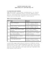
2.0 About This Document2.0 About This DocumentThis document provides the following:• Functional overview of the <strong>Intel</strong> ® IXP43X Product Line of Network Processors• Mechanical data (package signal locations and simulated thermal characteristics)• Targeted electrical specifications• Bus functional wave forms for the deviceDetailed functional description other than parametric performance is published in the<strong>Intel</strong> ® IXP43X Product Line of Network Processors Developer’s Manual.Other related documents are shown in Table 2.Table 2.Related DocumentsDocument Title Document #<strong>Intel</strong> XScale ® Processor Developer’s Manual 273473<strong>Intel</strong> XScale ® Microarchitecture Technical Summary —<strong>Intel</strong> ® IXP43X Product Line of Network Processors Developer’s Manual 316843<strong>Intel</strong> ® IXP4XX Product Line of Network Processors Specification Update 306428<strong>Intel</strong> ® IXP400 Software Programmer’s Guide 252539Enabling Time Synchronization (IEEE-1588) Hardware on <strong>Intel</strong>® IXP43X Product Line ofNetwork Processors Application NoteEnabling TMII Hardware on <strong>Intel</strong>® IXP43X Product Line of Networks Processors ApplicationNotePCI Local Bus Specification, Revision 2.2Universal Serial Bus Specification, Revision 1.1DDRI SpecificationDDRII Specification313857319092N/AN/AN/AN/A3.0 Functional OverviewThe <strong>Intel</strong> ® IXP43X Product Line of Network Processors is compliant with the <strong>Intel</strong> ®StrongARM * Version 5TE instruction-set architecture (ISA). The IXP43X networkprocessors are designed with <strong>Intel</strong> 0.13-micron semiconductor process technology. Thisprocess technology along with the compactness of the <strong>Intel</strong> ® StrongARM * RISC ISA,which has the ability to simultaneously process data with up to two integrated networkprocessing engines (NPE A and NPE C), and numerous dedicated-function peripheralinterfaces enables the IXP43X network processors to operate over a wide range of lowcost networking applications with industry-leading performance.As indicated in Figure 1, Figure 2, Figure 3, Figure 4, and Figure 5, the IXP43X networkprocessors combine many features with the <strong>Intel</strong> XScale ® Processor to create a highlyintegrated processor applicable to LAN/WAN-based networking applications in additionto other embedded networking applications.This section describes the main features of the product. For detailed functionaldescription, see the <strong>Intel</strong> ® IXP43X Product Line of Network Processors Developer’sManual.<strong>Intel</strong> ® IXP43X Product Line of Network ProcessorsDecember 2008DatasheetDocument Number: 316842; Revision: 003US 13
3.0 Functional OverviewFigure 1.<strong>Intel</strong> ® IXP435 Network Processor Block DiagramHSSUTOPIA 2/ MIINPE AMIINPE CNorth AHB 133. 32 MHz x 32 bits16 GPIOIEEE-1588SSPHigh SpeedUART921 KbaudGPIOInterruptControllerIBPMUAPB 66. 66MHz x 32 bi tsAHBSlave /APBMasterBRIDGEAES/ DES/SHA/ MD-5Queue Status BusQUEUEMANAGERNorth AHBArbiterSouth AHB 133. 32 MHz x 32 bitsSouth AHBArbiterAHB/ AHBBRIDGEDDRII/ I MEMORYCONTROLLERUNIT266 / 400MPI133.32MHz/200MHzx64 bits16/ 32 BITS+ ECCDDR 266 /DDRII 400TimersUSB PortHOSTCONTROLLERVERSION 2.0UTMI2.0 PHYUSB PortHOSTCONTROLLERVERSION 2.0UTMI2.0 PHYEXPANSIONBUS Controller8/16 bit 80MHzPCICONTROLLER32 bit 33 MHz<strong>Intel</strong> XScale®Processor32 KB I - CACHE32 KB D - CACHE2KB MINI D- CACHE400/533/667 MHzMaster on South AHBMaster on North AHBBus ArbitersSlave OnlyAHB Slave/ APB Master<strong>Intel</strong> ® IXP43X Product Line of Network ProcessorsDatasheet December 200814 Document Number: 316842; Revision: 003US
3.0 Functional OverviewFigure 2.<strong>Intel</strong> ® IXP433 Network Processor Block DiagramHSSMIINPE A16 GPIOIEEE-1588SSPHigh SpeedUART921 KbaudGPIOInterruptControllerIBPMUMIIAPB 66.66MHz x 32 bi tsAHBSlave /APBMasterBRIDGENPE CQueue Status BusQUEUEMANAGERNorth AHBArbiterSouth AHB 133.32 MHz x 32 bitsNorth AHB 133.32 MHz x 32 bitsSouth AHBArbiterAHB / AHBBRIDGEDDRII / I MEMORYCONTROLLERUNIT266 /400MPI133.32MHz/200MHz x64 bits16/ 32 BITS+ ECCDDR 266/DDRII 400TimersUSB PortHOSTCONTROLLERVERSION 2.0UTMI2. 0 PHYUSB PortHOSTCONTROLLERVERSION 2.0UTMI2. 0 PHYEXPANSIONBUS Controller8/16 bit 80MHzPCICONTROLLER32 bit 33 MHz,<strong>Intel</strong> XScale®Processor32 KB I - CACHE32 KB D - CACHE2KB MINI D- CACHE533 MHzMaster on South AHBMaster on North AHBBus ArbitersSlave OnlyAHB Slave / APB Master<strong>Intel</strong> ® IXP43X Product Line of Network ProcessorsDecember 2008DatasheetDocument Number: 316842; Revision: 003US 15
3.0 Functional OverviewFigure 3.<strong>Intel</strong> ® IXP432 Network Processor Block DiagramMIINPE AMIINPE CNorth AHB 133 .32 MHz x 32 bits16 GPIOIEEE-1588SSPHigh SpeedUART921 KbaudGPIOInterruptControllerIBPMUTimersAPB 66.66MHz x 32 bi t sAHBSlave /APBMasterBRIDGEUSB PortHOSTCONTROLLERVERSION 2. 0UTMI2.0 PHYAES / DES /SHA /MD- 5Queue Status BusQUEUEMANAGERNorth AHBArbiterSouth AHB 133.32 MHz x 32 bitsUSB PortHOSTCONTROLLERVERSION 2.0UTMI2.0 PHYSouth AHBArbiterEXPANSIONBUS Controller8 /16 bit 80MHzAHB / AHBBRIDGEPCICONTROLLER32 bit 33 MHz,DDRII / I MEMORYCONTROLLERUNIT266 / 400MPI13 3.3 2 MHz/200MHzx64 bits<strong>Intel</strong> XScale®Processor32KB I - CACHE32 KB D - CACHE2KB MINI D - CACHE400 MHz16/ 32 BITS+ ECCDDR 266 /DDRII 400Master on South AHBMaster on North AHBBus ArbitersSlave OnlyAHB Slave/ APB Master<strong>Intel</strong> ® IXP43X Product Line of Network ProcessorsDatasheet December 200816 Document Number: 316842; Revision: 003US
3.0 Functional OverviewFigure 4.<strong>Intel</strong> ® IXP431 Network Processor Block DiagramHSSUTOPIA 2NPE A16 GPIOIEEE-1588SSPHigh SpeedUART921 KbaudGPIOInterruptControllerIBPMUTimersMIIAPB 66. 66MHz x 32 bi tsAHBSlave/APBMasterBRIDGEUSB PortHOSTCONTROLLERVERSION 2.0UTMI2. 0 PHYNPE CQueue Status BusSouth AHB 133. 32USB PortHOSTCONTROLLERVERSION 2.0UTMI2.0 PHYQUEUEMANAGERNorth AHB 133 .32 MHz x 32 bitsNorth AHBArbiterMHz x 32 bitsSouth AHBArbiterEXPANSIONBUS Controller8/16 bit 80MHzAHB / AHBBRIDGEPCICONTROLLER32 bit 33 MHz,DDRII / I MEMORYCONTROLLERUNIT266 / 400MPI13 3. 3 2 MHz/200MHz x64 bits<strong>Intel</strong> XScale®Processor32 KB I - CACHE32 KB D - CACHE2KB MINI D -CACHE400 MHz16/ 32 BITS+ ECCDDR 266/DDRII 400Master on South AHBMaster on North AHBBus ArbitersSlave OnlyAHB Slave / APB Master<strong>Intel</strong> ® IXP43X Product Line of Network ProcessorsDecember 2008DatasheetDocument Number: 316842; Revision: 003US 17
3.0 Functional OverviewFigure 5.<strong>Intel</strong> ® IXP430 Network Processor Block DiagramMIINPE AMIINorth AHB 133.32 MHz x 32 bits16 GPIOIEEE-1588SSPHigh SpeedUART921 KbaudGPIOInterruptControllerIBPMUA P B 66. 6 6M H z x 3 2 bi t sAHBSlave/APBMasterBRIDGENPE CQueue StatusBusQUEUEMANAGERNorth AHBArbiterAHB/ AHBBRIDGESouth AHB 133. 32 MHz x 32 bitsSouth AHBArbiterDDRII / I MEMORYCONTROLLERUNIT266/ 400MPI133.32 MH z/200MH z x64 bits16 / 32 BITS+ ECCDDR 266/DDRII 400TimersUSB PortHOSTCONTROLLERVERSION 2.0UTMI2. 0 PHYUSB PortHOSTCONTROLLERVERSION 2.0UTMI2.0 PHYEXPANSIONBUS Controller8/16 bit 80MHzPCICONTROLLER32 bit 33 MHz<strong>Intel</strong> XScale®Processor32 KB I - CACHE32 KB D- CACHE2 KB MINI D -CACHE400/533/667 MHzMaster on South AHBMaster on North AHBBus ArbitersSlave OnlyAHB Slave/APB Master<strong>Intel</strong> ® IXP43X Product Line of Network ProcessorsDatasheet December 200818 Document Number: 316842; Revision: 003US
3.0 Functional Overview3.1 Key Functional UnitsThe following sections describe the functional units and their interaction in the system.For more detailed information, refer to the <strong>Intel</strong> ® IXP43X Product Line of NetworkProcessors Developer’s Manual.Unless otherwise specified, the functional description applies to all the networkprocessors in the IXP43X product line. For specific information on supported interfaces,refer to Table 1 on page 12. For model-specific block diagrams, see Figure 1 onpage 14, Figure 2 on page 15, Figure 3 on page 16, Figure 4 on page 17, and Figure 5on page 18.3.1.1 Network Processor Engines (NPEs)The Network Processor Engines (NPEs) are dedicated-function processors containinghardware coprocessors integrated into the IXP43X network processors. The NPEs areused to off-load processing function required by the <strong>Intel</strong> XScale processor.These NPEs are high-performance, hardware-multi-threaded processors with additionallocal hardware assist functionality used to off load highly processor intensive functionssuch as MII (MAC), CRC checking/generation, AAL segmentation and re-assembly, AES,AES-CCM, DES, 3DES, SHA-1/256/384/512, MD5, and so forth.All instruction code for the NPEs are stored locally and is accessed using a dedicatedinstruction memory bus. Similarly, separate dedicated data memory bus allows accessto local code store and DDRII/DDRI SDRAM through the AHB bus.These NPEs support processing of the dedicated peripherals that can include:• A universal test and operation PHY interface for ATM UTOPIA Level 2 interface• One high-speed serial (HSS) interface• Up to two media-independent interface (MII)Table 3 specifies the possible combination of interfaces for the NPEs contained in theIXP43X network processors. These configurations are determined by the factoryprogrammed fuse settings or by the software that configures the part during boot-up.Table 3.Network Processor FunctionsDeviceUTOPIALevel 2HSS MII A MII CAES / DES /3DESHDLCSHA/ MD-5Configuration 0 X X X X 4 XConfiguration 1 X X X X 4 XThe NPE core is a hardware-multi-threaded processor engine that is used to acceleratefunctions that are difficult to achieve high performance in a standard RISC processor.Each NPE core is a 133.32-MHz (or 4*OSC_IN input pin) processor core that hasself-contained instruction memory and self-contained data memory that operate inparallel. Each NPE core has 4 K x 29bit of instruction memory and 4 K words of datamemory.In addition to having separate instruction/data memory and local-code store, the NPEcore supports hardware multi-threading with support for multiple contexts. The supportof hardware multi-threading creates an efficient processor engine with minimalprocessor stalls due to the ability of the processor core to switch contexts in a singleclock cycle, based on a prioritized/preemptive basis. The prioritized/preemptive natureof the context switching allows time-critical applications to be implemented in alow-latency fashion that are required while processing multi-media applications.<strong>Intel</strong> ® IXP43X Product Line of Network ProcessorsDecember 2008DatasheetDocument Number: 316842; Revision: 003US 19
3.0 Functional OverviewThe NPE core also connects to several hardware-based coprocessors that are used toimplement functions that are difficult for a processor to implement. These functionsinclude:• HSS serialization/ De-serialization• DES/3DES/AES• MD-5• UTOPIA Level 2 Framing• CRC checking/generation• SHA-1/256/384/512• HDLC bit stuffing/de-stuffing• Fast Ethernet Media AccessController functionalityThese coprocessors are implemented in hardware, enabling the coprocessors and theNPE processor core to operate in parallel.The combined forces of the hardware multi-threading, local-code store, independentinstruction memory, independent data memory, and parallel processing contained onthe NPE allows the <strong>Intel</strong> XScale processor to be utilized for application purposes. Themulti-processing capability of the peripheral interface functions allows unparalleledperformance to be achieved by the application running on the <strong>Intel</strong> XScale processor.3.1.2 Internal Bus3.1.2.1 North AHBThe internal bus architecture of the IXP43X network processors is designed to allowparallel processing to occur and to isolate bus utilization, based on particular trafficpatterns. The bus is segmented into four major buses:• North advanced, high-performance bus(AHB)• South AHB• Memory port interface• Advanced peripheral bus(APB)The North AHB is a 133.32-MHz, 32-bit bus that can be mastered by the NPE A, or NPEC. The targets of the North AHB can be the DDRII/DDRI SDRAM or the AHB/AHBbridge. The AHB/AHB bridge allows the NPEs to access peripherals and internal targetson the South AHB.Data transfers by the NPEs on the North AHB to the South AHB are targetedpredominately to the queue manager. Transfers to the AHB/AHB bridge can be postedwhen writing or split when reading.When a transaction is posted, a master on the North AHB requests a write to aperipheral on the South AHB. If the AHB/AHB Bridge has a free FIFO location, the writerequest is transferred from the master on the North AHB to the AHB/AHB bridge. TheAHB/AHB bridge completes a write on the South AHB once it obtains access to theperipheral on the South AHB. The North AHB is released to complete anothertransaction.When a transaction is split, a master on the North AHB requests a read of a peripheralon the South AHB. If the AHB/AHB bridge has a free FIFO location, the read request istransferred from the master on the North AHB to the AHB/AHB bridge. The AHB/AHBbridge completes a read on the South AHB once it obtains access to the peripheral onthe South AHB.Once the AHB/AHB bridge has obtained the read information from the peripheral on theSouth AHB, the AHB/AHB bridge notifies the arbiter, on the North AHB, that the AHB/AHB bridge has the data for the master that requested the split transfer. The masteron the North AHB that requested the split transfer arbitrates for the North AHB and<strong>Intel</strong> ® IXP43X Product Line of Network ProcessorsDatasheet December 200820 Document Number: 316842; Revision: 003US
3.0 Functional Overview3.1.2.2 South AHBtransfers the read data from the AHB/AHB bridge. The North AHB is released tocomplete another transaction as the North AHB master that requested the split transferwaits for the data to arrive.These posting and splitting transfers allow control of the North AHB to be given toanother master on the North AHB enabling the North AHB to achieve maximumefficiency. Transfers to the AHB/AHB bridge are considered to be small and infrequent,relative to the traffic passed between the NPEs and the DDRII/DDRI SDRAM on theNorth AHB.When multiple masters arbitrate for the North AHB, the masters are awarded access tothe bus in a round-robin fashion. Each transaction is no longer than an eight-wordburst. This implementation promotes fairness within the system.The South AHB is a 133.32-MHz (that is 4*OSC_IN input pin), 32-bit bus that can bemastered by the <strong>Intel</strong> XScale processor, PCI controller, USB Host Controller, and theAHB/AHB bridge. The targets of the South AHB Bus can be the DDRII/DDRI SDRAM,PCI Controller, Queue Manager, Expansion Bus, or the AHB/APB bridge.Accessing across the APB/AHB bridge allows interfacing to peripherals attached to theAPB. The Expansion bus and PCI controller can be configured to support split transfers.Arbitration on the South AHB are round-robin. Each transaction to be no longer than aneight-word burst. This implementation promotes fairness within the system.3.1.2.3 Memory Port Interface3.1.2.4 APB BusThe Memory Port Interface (MPI) is a 64-bit bus that provides the <strong>Intel</strong> XScaleprocessor a dedicated interface to the DDRII/DDRI SDRAM. The Memory Port Interfaceoperates at 133.32 MHz when DDRI SDRAM is used, and 200 MHz when DDRII SDRAMis usedThe Memory Port Interface stores memory transactions from the <strong>Intel</strong> XScaleprocessor, which have not been processed by the Memory Controller. The Memory PortInterface supports eight core processor read transactions up to 32 bytes each. Thattotal equals the maximum number of outstanding transaction the Core Processor BusController can support. (That includes core DCU [4 - load requests to unique cachelines], IFU [2 - prefetch], IMM [1 - tablewalk], DMM [1 - tablewalk].)The Memory Port Interface also supports eight core-processor-posted writetransactions up to 16 bytes each.Arbitration on the Memory Port Interface is not required due to no contention withother masters. Arbitration exists in the DDRII/DDRI memory controller between all ofthe main internal busses.The APB Bus is a 66.66-MHz, 32-bit bus that is mastered by the AHB/APB bridge only.The targets of the APB bus are:• Timers• UART<strong>Intel</strong> ® IXP43X Product Line of Network ProcessorsDecember 2008DatasheetDocument Number: 316842; Revision: 003US 21
3.0 Functional Overview• The internal bus performance monitoring unit(IBPMU)• GPIOs• Synchronous Peripheral Port Interface• All NPEs• Interrupt controller• IEEE-1588 Hardware AssistThe APB interface is also used as an alternate-path interface to the NPEs and is usedfor NPE code download and configuration.No arbitration is required due to a single master implementation.3.1.3 MII InterfacesThe IXP43X product line of network processors can be configured to support up to twoindustry-standard MII interfaces. These interfaces are integrated into the IXP43Xnetwork processors with separate media-access controllers and in many casesindependent network processing engines. Refer Table 3 for allowable combinations.The independent NPEs and MACs allow parallel processing of data traffic on the MIIinterfaces and off loading of processing required by the <strong>Intel</strong> XScale processor. TheIXP43X network processors are compliant with IEEE 802.3 specification.In addition to the MII interfaces, the IXP43X network processors includes a singlemanagement data interface that is used to configure and control PHY devices that areconnected to the MII interfaces.TMII (Turbo Media Independent Interface), also called Turbo MII, is used to increasethe MII clock from 25 MHz to 50 MHz. The purpose of the Turbo MII is to enhance LANthroughput performance by doubling the MII clock rate. TMII is supported in <strong>Intel</strong>®IXP400 Software Release 3.01. Please refer to the Enabling TMII Hardware on <strong>Intel</strong>®IXP435 Product Line of Networks Processors Application Note for more information.3.1.4 UTOPIA Level 2 InterfaceThe integrated UTOPIA Level 2 interface works with a network-processing engine corefor several of the IXP43X network processors. The pins of the UTOPIA Level 2 interfaceare multiplexed with one of the MII interfaces. Refer Table 3 for additional information.The UTOPIA Level 2 interface supports a single- or a multiple-physical-interfaceconfiguration with cell-level or octet-level handshaking. The network processing enginehandles segmentation and reassembly of ATM cells, CRC checking/generation, andtransfer of data to/from memory. This allows parallel processing of data traffic on theUTOPIA Level 2 interface, off-loading these processing tasks from the <strong>Intel</strong> XScaleprocessor.The IXP43X network processors are compliant with the ATM Forum, UTOPIA Level-2Specification, Revision 1.0.3.1.5 USB Version 2.0 Host InterfaceUSB Host functionality is implemented on the IXP43X network processors. The functionbeing performed is defined by the USB 2.0 specification, maintained by usb.org and theinterface is EHCI compliant, as defined by <strong>Intel</strong>.Supported features are:• Host function• Low-speed interface<strong>Intel</strong> ® IXP43X Product Line of Network ProcessorsDatasheet December 200822 Document Number: 316842; Revision: 003US
3.0 Functional Overview• Full-speed interface• High-speed interface• EHCI register interface• UTMI+ Level 2 CompliantThe following is a partial list of features that are not supported:• Device function• OTG function3.1.6 PCI ControllerThe PCI controller in the IXP43X network processors is compatible with the PCI LocalBus Specification, Rev. 2.2. The PCI interface is 32-bit compatible bus and capable ofoperating as either a host or an option (that is, not the Host). This PCI implementationsupports 3.3 V I/O and 33 MHz only.3.1.7 DDRII/DDRI Memory ControllerThe IXP43X network processors integrate a high-performance, multi-ported MemoryController Unit (MCU) to provide a direct interface between IXP43X network processorsand their local memory subsystem. The MCU supports:• DDRI 266 or DDRII-400 SDRAM• 128/256/512-Mbit, 1-Gbit DDRI SDRAM technology support• Supports 256/512-Mbit technologies for DDRII-400• Only unbuffered DRAM support (No registered DRAM support)• Dedicated port for <strong>Intel</strong> XScale processor to DDRII/DDRI SDRAM• Between 32 MBs and 1-GB of 32-bit DDRI SDRAM• Between 64MBs and 512 MBs of 32-bit DDRII SDRAM• 16MB for 16-bit memory systems for DDRI SDRAM (non-ECC) supporting 128-Mbittechnology only• 32MB / 64MB for 16-bit memory systems for DDRII SDRAM (non-ECC) supporting256-Mbit / 512-Mbit technology.• Single-bit error correction, multi-bit detection support (ECC)• 32-bit, 40-bit wide memory interfaces (non-ECC and ECC support), and 16-bit widememory interfaces (non-ECC)The DDRII/DDRI SDRAM interface provides a direct connection to a high-bandwidthand reliable memory subsystem. The DDRII/DDRI SDRAM interface is a 16 or 32-bitwidedata path.An 8-bit Error Correction Code (ECC) across each 32-bit word improves systemreliability. It is important to note that ECC is also referred to as CB in many DIMMspecifications. The pins on the IXP43X network processors are calledDDR_CB[7:0]. ECC is only implemented in the 32-bit mode of operation. The algorithmused to generate the 8-bit ECC is implemented over 64-bit.The ECC circuitry is designed to operate always on a 64-bit data and when operating in32-bit mode, the upper 32 bits are driven to zeros internally. To summarize the impactto the customer, the full 8 bits of ECC is stored and read from a memory array for theECC logic to work. An 8-bit-wide memory is used when implementing ECC.<strong>Intel</strong> ® IXP43X Product Line of Network ProcessorsDecember 2008DatasheetDocument Number: 316842; Revision: 003US 23
3.0 Functional OverviewThe memory controller only corrects single bit ECC errors on read cycles. The ECC isstored into the DDRII/DDRI SDRAM array along with the data and is checked when thedata is read. If the code is incorrect, the MCU corrects the data (if possible) beforereaching the initiator of the read. ECC error scrubbing is done with software.User-defined fault correction software is responsible for scrubbing the memory arrayand handling double-bit errors.To limit double-bit errors from occurring, periodically reading the entire usable memoryarray allows the hardware unit within the memory controller to correct any single-bit,ECC errors that may have occurred prior to these errors becoming double-bit ECCerrors. Implementing this method is system-dependent.It is important to note that when sub-word writes (byte writes or half-word writeswithin aword-aligned boundary) are done to a 32-bit memory with ECC enabled, the memorycontroller performs read-modify writes. There is a performance impact withread-modify writes that must be considered when writing software.With read-modify writes, the memory controller reads the 32-bit word thatencompasses the byte that is to be written when a byte write is requested. Thememory controller modifies the specified byte, calculates a new ECC, and writes theentire 32-bit word back into the memory location it was read from.The value written back into the memory location contains the 32-bit word with themodified byte and the new ECC value.The MCU supports two physical banks of DDRII/DDRI SDRAM. The MCU has support forunbuffered DDRI 266 and DDRII 400 in the form of discrete chips only.The MCU supports a memory subsystem ranging from 32 MB to 1 GB for 32-bitmemory systems for DDRI SDRAM, from 64 MB to 512 MB for 32-bit memory systemsfor DDRII SDRAM, and supports 16 MB for 16-bit memory systems for DDRI SDRAM(non-ECC), and 32 MB for 16-bit memory systems for DDRII SDRAM (non-ECC). AnECC or non-ECC system can be implemented using x8, or x16 devices. Table 4, Table 5,Table 6 and Table 7 illustrate the supported DDRII/DDRI SDRAM configurationsThe two DDRII/DDRI SDRAM chip enables (DDR_CS_N[1:0]) support a DDRII/DDRISDRAM memory subsystem consisting of two banks. The base address for the twocontiguous banks are programmed in the DDRII/DDRI SDRAM Base Register (SDBR)and is aligned to a 16 MB boundary. The size of each DDRII/DDRI SDRAM bank isprogrammed with the DDRII/DDRI SDRAM boundary registers (SBR0 and SBR1).The DDRII/DDRI SDRAM devices comprise four internal leaves. The MCU controls theleaf selects within DDRII/DDRI SDRAM by toggling DDR_BA[0] and DDR_BA[1].Table 4. Supported DDRI 32-bit SDRAM Configurations (Sheet 1 of 2)DDR SDRAMTechnologyDDR SDRAMArrangement128 Mbit c 16 M x 8256 Mbit8 M x 1632 M x 816 M x 16# BanksAddress SizeLeaf SelectRow Column DDR_BA[1] DDR_BA[0]Total MemorySize aPageSize b164 M 4KB12 10 ADDR[26] ADDR[25]2 128 M 4KB132 M 2KB12 9 ADDR[25] ADDR[24]2 64 M 2KB1128 M 4KB13 10 ADDR[27] ADDR[26]2 256 M 4KB164 M 2KB13 9 ADDR[26] ADDR[25]2 128 M 2KB<strong>Intel</strong> ® IXP43X Product Line of Network ProcessorsDatasheet December 200824 Document Number: 316842; Revision: 003US
3.0 Functional OverviewTable 4. Supported DDRI 32-bit SDRAM Configurations (Sheet 2 of 2)DDR SDRAMTechnology512 MbitDDR SDRAMArrangement64 M x 832 M x 161Gbit c 128 M x 864 M x 16# BanksAddress SizeLeaf SelectRow Column DDR_BA[1] DDR_BA[0]Total MemorySize aPageSize b1256 M 8KB13 11 ADDR[28] ADDR[27]2 512 M 8KB1128 M 4KB13 10 ADDR[27] ADDR[26]2 256 M 4KB1512 M 8KB14 11 ADDR[29] ADDR[28]2 1 G 8KB1256 M 4KB14 10 ADDR[28] ADDR[27]2 512 M 4KBa. Table indicates 32-bit wide memory subsystem sizes.b. Table indicates 32-bit wide memory page sizes.c. Supported with DDR SDRAM onlyTable 5.Supported DDRII 32-bit SDRAM ConfigurationsDDR SDRAMTechnologyDDR SDRAMArrangement# ofBanksAddress SizeLeaf SelectRow Column DDR_BA[1] DDR_BA[0]TotalMemory SizePageSize256 Mbit512 Mbit32M x 816M x1664M x 832M x161128MB 4KB13 10 ADDR[27] ADDR[26]2 256MB 4KB164MB2KB13 9 ADDR[26] ADDR[25]2 128MB 2KB1256MB 4KB14 10 ADDR[28] ADDR[27]2 512MB 4KB1128MB 4KB13 10 ADDR[27] ADDR[26]2 256MB 4KBTable 6.Supported DDRI 16-bit SDRAM ConfigurationsDDR SDRAMTechnologyDDR SDRAMArrangement# ofBanksAddress SizeLeaf SelectRow Column DDR_BA[1] DDR_BA[0]TotalMemory SizePageSize128 Mbit 8M x16 1 12 9 ADDR[23] ADDR[22] 16MB 1KBTable 7.Supported DDRII 16-bit SDRAM ConfigurationsDDR SDRAMTechnologyDDR SDRAMArrangement# ofBanksAddress SizeLeaf SelectRow Column DDR_BA[1] DDR_BA[0]Total MemorySizePageSize256 Mbit 16M x16 1 13 9 ADDR[24] ADDR[23] 32MB 1KB512 Mbit 32M x16 1 13 10 ADDR[27] ADDR[26] 64MB 4KBThe memory controller internally interfaces with the North AHB, South AHB, andMemory Port Interface with independent interfaces. This architecture allowsDDRII/DDRI SDRAM transfers to be interleaved and pipelined to achieve maximumpossible efficiency.<strong>Intel</strong> ® IXP43X Product Line of Network ProcessorsDecember 2008DatasheetDocument Number: 316842; Revision: 003US 25
3.0 Functional OverviewThe MCU supports DDRII/DDRI SDRAM burst length of four for 32-bit and 16-bit databus width options. A burst length of four enables seamless read/write bursting of longdata streams as long as the memory transaction does not cross the page boundary.Page boundaries are at naturally aligned boundaries. The MCU ensures that the pageboundary is not crossed within a single transaction by initiating a disconnect at nextADB (128-byte address boundary) on the internal bus prior to the page boundary.The programming priority of the MCU is for the Memory Port Interface to have thehighest priority and two AHB ports has the next highest priority. For more informationon MCU arbitration support and configuration see the <strong>Intel</strong> ® IXP43X Product Line ofNetwork Processors Developer’s Manual.One item to be aware of is that when ECC is being used, the memory chip chosen tosupport the ECC must match that of the technology chosen on the interface. Therefore,if x8 in a given configuration technology is chosen then the ECC memory chip is thesame. If a x16 configuration is chosen then a x16 chip is to be used for the ECC chip.3.1.8 Expansion InterfaceThe expansion interface allows easy and in most cases glue-less connection toperipheral devices. It also provides input information for device configuration afterreset.Some of the peripheral device types are <strong>Intel</strong> multiplexed, <strong>Intel</strong> non-multiplexed,Numonyx* StrataFlash ® , Synchronous Numonyx* StrataFlash ® Memory, Motorolamultiplexed and Motorola non-multiplexed target devices.The expansion interface functions support 8-bit or 16-bit data operation and allows anaddress range of 512 bytes to 16 MBs, using 24 address lines for each of the fourindependent chip selects.Access to the expansion-bus interface is completed in five phases. Each of the fivephases can be lengthened or shortened by setting various configuration registers on aper-chip-select basis. This feature allows the IXP43X network processors to connect toa wide variety of peripheral devices with varying speeds.The expansion interface supports <strong>Intel</strong> or Motorola microprocessor-style bus cycles.The bus cycles can be configured to be multiplexed address/data cycles or separateaddress/data cycles for each of the four chip-selects.The expansion interface is an asynchronous interface to externally connected chips. Aclock is supplied to the IXP43X network processors expansion interface for properoperation. This clock can be driven from GPIO 15 or an external source. Devices on theexpansion bus can be clocked by an external clock at a rate of up to 80 MHz. If GPIO 15is used as the clock source, the Expansion Bus interface can only be clocked at amaximum of 33.33 MHz. GPIO 15’s maximum clock rate is 33.33 MHz.3.1.9 High-Speed Serial InterfaceThe high-speed serial interface (HSS) is a six-signal interface that support serialtransfer speeds from 512 KHz to 8.192 MHz, for some of the IXP43X networkprocessors.The interface allows direct connection of up to four T1/E1 framers and CODEC/SLICs tothe IXP43X network processors. The high-speed, serial interface is capable ofsupporting various protocols, based on the implementation of the code developed forthe network processor engine core.For a list of supported protocols, see the <strong>Intel</strong> ® IXP400 Software Programmer’s Guide.<strong>Intel</strong> ® IXP43X Product Line of Network ProcessorsDatasheet December 200826 Document Number: 316842; Revision: 003US
3.0 Functional Overview3.1.10 UART Interface3.1.11 GPIOThe UART interface is a 16550-compliant UART with the exception of transmit andreceive buffers. Transmit and receive buffers are 64 bytes-deep versus the 16 bytesrequired by the 16550 UART specification.The interface can be configured to support speeds from 1,200 Baud to 921 Kbaud. Theinterface supports the following configurations:• Five, six, seven, or eight data-bit transfers• One or two stop bits• Even, odd, or no parityThe request-to-send (RTS0_N) and clear-to-send (CTS0_N) modem control signals alsoare available with the interface for hardware flow control.16 GPIO pins are supported by the IXP43X network processors. The GPIO pins 0through 15 can be configured to be general-purpose input or general-purpose output.Additionally, GPIO pins 0 through 12 can be configured to be an interrupt input.GPIO Pin 1 can also be configured as a clock input for an external USB 2.0 Host Bypassclock. When spread spectrum clocking (SSC) is used, an external clock should be usedas the source for the USB 2.0 Host clock. Refer to the <strong>Intel</strong> ® IXP43X Product Line ofNetwork Processors Developer’s Manual for more information.GPIO Pin 14 and GPIO 15 can also be configured as a clock output. The output-clockconfiguration can be set at various speeds, up to 33.33 MHz, with various duty cycles.GPIO Pin 14 is configured as an input, upon reset. GPIO Pin 15 is configured as anoutput, upon reset. GPIO Pin 15 can be used to clock the expansion interface, afterreset.Table 8.GPIO Alternate Function TableGPIO Pin Number GPIO function Alternate Function0 General purpose input/output or interrupt source Reserved1 † General purpose input/output or interrupt sourceExternal USB 48 MHz BypassClock2 General purpose input/output or interrupt source Reserved3 General purpose input/output or interrupt source Reserved4 General purpose input/output or interrupt source Reserved5 General purpose input/output or interrupt source Reserved6 General purpose input/output or interrupt source Reserved7 General purpose input/output or interrupt sourceAuxiliary IEEE-1588 MasterSnapshot8 General purpose input/output or interrupt sourceAuxiliary IEEE-1588 SlaveSnapshot9:12 General purpose input/output or interrupt source Reserved13 General purpose input/output Reserved<strong>Intel</strong> ® IXP43X Product Line of Network ProcessorsDecember 2008DatasheetDocument Number: 316842; Revision: 003US 27
3.0 Functional OverviewTable 8.GPIO Alternate Function TableGPIO Pin Number GPIO function Alternate Function14 General purpose input/output or output clock Output clock 1415 Output Clock or General purpose input/output Output clock 15† When a spread spectrum clock is used, GPIO Pin 1 should be configured as an input clock for USBHost. See the <strong>Intel</strong> ® IXP43X Product Line of Network Processors Developer’s Manual for detailedinformation.3.1.12 Internal Bus Performance Monitoring Unit (IBPMU)The IXP43X network processors contain a performance monitoring unit that can beused to capture predefined events within the system outside of the <strong>Intel</strong> XScaleprocessor. These features aid in measuring and monitoring various system parametersthat contribute to the overall performance of the processor.The Performance Monitoring (PMON) facility provided comprises:• Eight Programmable Event Counters (PECx) clocked by AHB clock(133MHz)• Eight Programmable Event Counters (MPECx) clocked by MCU clock(133MHz/200MHz)• Previous Master/Slave Register• Event Selection Multiplexor• Simultaneous event countingThe programmable event counters are 27 bits wide. Each counter can be programmedto observe one event from a defined set of events. An event consists of a set ofparameters that define a start condition and a stop condition.The monitored events are selected by programming the Event Select Registers (ESR).3.1.13 Interrupt Controller3.1.14 TimersThe IXP43X network processors implement up to 64 interrupt sources to allow anextension of the FIQ and IRQ interrupt sources of <strong>Intel</strong> XScale processor. Thesesources can originate from some external GPIO pins, internal peripheral interfaces, orinternal logic.The interrupt controller can configure each interrupt source as an FIQ, IRQ, or disabled.The interrupt source are prioritize in an ascending order.For example, Interrupt 0 hashigher priority than 1,Interrupt 8 has a higher priority than 9, 9 has a higher prioritythan 10, and 30 has a higher priority that 31.Additionally, the interrupt sources tied to Interrupt 0 to 7 can be prioritized. Forexample, Interrupt 7 can be prioritize over Interrupt 0.The IXP43X network processors contain four internal timers operating at 66.66 MHz(that is 2*OSC_IN input pin) that allows task scheduling and prevent softwarelock-ups. The device has four 32-bit counters:• Watch-Dog Timer • Timestamp Timer • Two general-purpose Timers<strong>Intel</strong> ® IXP43X Product Line of Network ProcessorsDatasheet December 200828 Document Number: 316842; Revision: 003US
3.0 Functional OverviewThe Timestamp Timer and the two general-purpose timers have the optional ability touse a pre-scaled clock. A programmable pre-scaler can be used to divide the inputclock by a 16-bit value. The input clock can be either the APB clock (66.66 MHz) or a20-ns version of the APB clock (50 MHz). By default all timers use the APB clock.The 16-bit pre-scale value ranges from divide by 2 to 65,536 and results in a new clockenable available for the timers that ranges from 33.33 MHz down to 1,017.26 Hz.The Timestamp Timer also contains a 32-bit compare register that allows an interruptto be created at times other than time 0.3.1.15 IEEE-1588 Hardware AssistIn a distributed control system containing multiple clocks, individual clocks tend to driftapart. Some kind of correction mechanism is necessary to synchronize the individualclocks to maintain global time, which is accurate to some clock resolution. The IEEE-1588 standard for a precision clock synchronization protocol for networkedmeasurement and control systems can be used for this purpose. The IEEE-1588standard defines several messages that can be used to exchange timing information.The IXP43X network processors implement the IEEE-1588 hardware-assist logic onthree of the MII interfaces. Using the hardware assist logic along with software runningon the <strong>Intel</strong> XScale ® processor, a full source or sink capable IEEE-1588 compliantnetwork node can be implemented.The GPIO[8:7] pins must be tied with a 10KΩ pull-down resistor when using the IEEE-1588 feature.Please refer to the Enabling Time Synchronization (IEEE-1588) Hardware on <strong>Intel</strong>®IXP43X Product Line of Networks Processors Application Note for more information onsoftware requirements.3.1.16 Synchronous Serial Port InterfaceThe IXP43X network processors have a dedicated Synchronous Serial Port (SSP)interface. The SSP interface is a full-duplex synchronous serial interface. It can connectto a variety of external analog-to-digital (A/D) converters, audio and telecom CODECs,and many other devices that use serial protocols for transferring data.It supports National’s Microwire, Synchronous Serial Protocol (SSP) of TexasInstruments, and Serial Peripheral Interface (SPI) protocol of Motorola.The SSP operates in master mode (the attached peripheral functions as a slave), andsupports serial bit rates from 7.2 Kbps to 1.8432 Mbps using the on-chip, 3.6864-MHzclock. Serial data formats may range from 4 to 16 bits in length. Two on-chip registerblocks function as independent FIFOs for data, one for each direction. The FIFOs are 16entries deep x 16 bits wide. Each 32-bit word from the system fills one entry in a FIFOusing the lower half 16-bits of a 32-bit word.3.1.17 AES/DES/SHA/MD-5The IXP43X network processors implement chip hardware acceleration for underlyingsecurity and authentication algorithms.The encryption/decryption algorithms supported are AES, single pass AES-CCM, DES,and triple DES. These algorithms are commonly found when implementing IPSEC, VPN,WEP, WEP2, WPA, and WPA2.<strong>Intel</strong> ® IXP43X Product Line of Network ProcessorsDecember 2008DatasheetDocument Number: 316842; Revision: 003US 29
3.0 Functional OverviewThe authentication algorithms supported are MD-5, SHA-1, SHA-256, SHA-384, andSHA-512. Inclusion of SHA-384 and SHA-512 allows 256-bit key authentication to pairup with 256-bit AES support.3.1.18 Queue ManagerThe Queue Manager provides a means for maintaining coherency for data handlingbetween various processor cores contained on the IXP43X network processors (NPE toNPE, NPE to <strong>Intel</strong> XScale processor, and so on). It maintains the queues as circularbuffers in an embedded 8-Kbyte SRAM. The Queue Manager also implements the statusflags and pointers required for each queue.The Queue Manager manages 64 independent queues. Each queue can be configuredfor buffer and entry size. Additionally status flags are maintained for each queue.The Queue Manager interfaces include an Advanced High-performance Bus (AHB)interface to the NPEs and <strong>Intel</strong> XScale processor (or any other AHB bus master), a FlagBus interface, an event bus (to the NPE condition select logic), and two interrupts tothe <strong>Intel</strong> XScale processor.The AHB interface is used for configuration of the Queue Manager and provides accessto queues, queue status, and SRAM. Individual queue status for queues 0-31 iscommunicated to the NPEs through the flag bus. Combined queue status for queues32-63 are communicated to the NPEs through the event bus. The two interrupts, onefor queues 0-31 and one for queues 32-63, provide status interrupts to the <strong>Intel</strong> XScaleprocessor.3.2 <strong>Intel</strong> XScale ® ProcessorThe <strong>Intel</strong> XScale technology is compliant with the <strong>Intel</strong> ® StrongARM * Version 5TEinstruction-set architecture (ISA). The <strong>Intel</strong> XScale processor, shown in Figure 6, isdesigned with <strong>Intel</strong> 0.13-micron production semiconductor process technology. Thisprocess technology, with the compactness of the <strong>Intel</strong> ® StrongARM * RISC ISA enablesthe <strong>Intel</strong> XScale processor to operate over a wide speed and power range, producingindustry-leading mW/MIPS performance.The features of the <strong>Intel</strong> XScale processor include:• Seven/eight-stage super-pipeline promotes high-speed, efficient core performance• 128-entry branch target buffer keeps pipeline filled with statistically correct branchchoices• 32-entry instruction memory-management unit for logical-to-physical addresstranslation, access permissions, and Instruction-Cache (I-cache) attributes• 32-entry data-memory management unit for logical-to-physical addresstranslation, access permissions, Data-Cache (D-Cache) attributes• 32-Kbyte instruction cache can hold entire programs, preventing core stalls causedbymulti-cycle memory access• 32-Kbyte data cache reduces core stalls caused by multi-cycle memory accesses• 2-Kbyte mini-data cache for frequently changing data streams avoids thrashing oftheD-cache• Four-entry, fill-and-pend buffers to promote core efficiency by allowinghit-under-miss operation with data caches• Eight-entry write buffer allows the core to continue execution while writing data tomemory<strong>Intel</strong> ® IXP43X Product Line of Network ProcessorsDatasheet December 200830 Document Number: 316842; Revision: 003US
3.0 Functional Overview• Multiple-accumulate coprocessor that can do two simultaneous, 16-bit, SIMDmultiplies with 40-bit accumulation for efficient, high-quality media and signalprocessing• Performance monitoring unit (PMU) furnishing four 32-bit event counters and one32-bit cycle counter for analysis of hit rates, and so on.This PMU is for the <strong>Intel</strong> XScale processor only. An additional PMU is supplied formonitoring of internal bus performance.• JTAG debug unit that uses hardware break points and 256-entry trace historybuffer (forflow-change messages) to debug programsFigure 6.<strong>Intel</strong> XScale ® Technology Block Diagram3.2.1 Super PipelineThe super pipeline comprises integer, multiply-accumulate (MAC), and memory pipes.The integer pipe has seven stages:• Branch Target Buffer (BTB)/Fetch 1• Fetch 2• Decode• Register File/Shift• ALU Execute• State Execute• Integer WritebackThe memory pipe has eight stages:• The first five stages of the Integer pipe explained above (that is, BTB/Fetch 1 toALU Execute) and ends with the following three memory stages:— Data Cache 1— Data Cache 2<strong>Intel</strong> ® IXP43X Product Line of Network ProcessorsDecember 2008DatasheetDocument Number: 316842; Revision: 003US 31
3.0 Functional Overview— Data Cache Writeback— The MAC pipe has six to nine stages:• The first four stages of the Integer pipe explained above (that is, BTB/Fetch 1 toALU Execute) and ends with the following MAC stages:—MAC1—MAC2—MAC3—MAC4— Data Cache WritebackThe MAC pipe supports a data-dependent early terminate where stages MAC 2, MAC 3,and/or MAC 4 are bypassed.Deep pipes promote high instruction execution rates only when there is a way topredict successfully the outcome of branch instructions. The branch target bufferprovides this way.3.2.2 Branch Target BufferEach entry of the 128-entry Branch Target Buffer (BTB) contains address of a branchinstruction, the target address associated with the branch instruction, and previoushistory of the branch being taken or not taken. The history is recorded as one of thefollowing four states:• Stronglytaken• Weakly taken• Weakly nottaken• Strongly not takenThe BTB can be enabled or disabled through Coprocessor 15, Register 1.When the address of the branch instruction hits in the BTB and its history is strongly orweakly taken, the instruction at the branch target address is fetched. When its historyis not taken strongly or weakly, the next sequential instruction is fetched. In either casethe history is updated.Data associated with a branch instruction enters the BTB the first time the branch istaken. This data enters the BTB in a slot with a history of strongly not-taken. That is itoverwrites the existing data.Successfully predicted branches avoid any branch-latency penalties in the superpipeline. Unsuccessfully predicted branches result in a four-to-five-cycle branch-latencypenalty in the super pipeline.3.2.3 Instruction Memory Management UnitFor instruction pre-fetches, the Instruction Memory Management Unit (IMMU) controlslogical-to-physical address translation, memory access permissions, memory-domainidentifications, and attributes. Governing operation of the instruction cache arecategorized as attributes.The IMMU contains a 32-entry, fully associative instruction-translation, look-asidebuffer (ITLB) that has a round-robin replacement policy. ITLB entries zero through 30can be locked.When an instruction pre-fetch misses in the ITLB, the IMMU invokes an automatictable-walk mechanism that fetches an associated descriptor from memory and loads itinto the ITLB. The descriptor contains information for logical-to-physical address<strong>Intel</strong> ® IXP43X Product Line of Network ProcessorsDatasheet December 200832 Document Number: 316842; Revision: 003US
3.0 Functional Overviewtranslation, memory-access permissions, memory-domain identifications, andattributes governing operation of the I-cache. The IMMU then continues the instructionpre-fetch by using the address translation just entered into the ITLB. When aninstruction pre-fetch hits in the ITLB, the IMMU continues the pre-fetch using theaddress translation already resident in the ITLB.Access permissions for each up to 16 memory domains can be programmed. When aninstruction pre-fetch is attempted to an area of memory in violation of accesspermissions, the attempt is aborted and a pre-fetch abort is sent to the core forexception processing. You can either enable or disable the IMMU and DMMU together.3.2.4 Data Memory Management UnitFor data fetches, the Data Memory Management Unit (DMMU) controlslogical-to-physical address translation, memory-access permissions, memory-domainidentifications, and attributes. Governing operation of the data cache or mini-datacache and write buffer are categorized as attributes. The DMMU contains 32-entry, fullyassociative data-translation, look-aside buffer (DTLB) that has a round-robinreplacement policy. DTLB entries 0 through 30 can be locked.When a data fetch misses in the DTLB, the DMMU invokes an automatic table-walkmechanism that fetches an associated descriptor from memory and loads it into theDTLB. The descriptor contains information for logical-to-physical address translation,memory-access permissions, memory-domain identifications, and attributes (governingoperation of the D-cache or mini-data cache and write buffer).The DMMU continues the data fetch by using the address translation just entered intothe DTLB. When a data fetch hits in the DTLB, the DMMU continues the fetch using theaddress translation already resident in the DTLB.Access permissions for each of up to 16 memory domains can be programmed. When adata fetch is attempted to an area of memory in violation of access permissions, theattempt is aborted and a data abort is sent to the core for exception processing.You can either enable or disable the IMMU and DMMU together.3.2.5 Instruction CacheThe Instruction Cache (I-Cache) can contain high-use, multiple-code segments orentire programs, allowing core access to instructions at core frequencies. This preventscore stalls, caused bymulti-cycle accesses to external memory.The 32-Kbyte I-cache is 32-set/32-way associative, where each set contains 32 waysand each way contains a tag address, a cache line of instructions (eight 32-bit wordsand one parity bit per word), and a line-valid bit. For each of the 32 sets, 0 through28 ways can be locked. Unlocked ways are replaceable through round-robin policy.The I-cache can be enabled or disabled. Attribute bits within the descriptors containedin the ITLB of the IMMU provide some control over an enabled I-cache.When a needed line (eight 32-bit words) is not present in the I-cache, the line isfetched (critical word first) from memory through a two-level, deep-fetch queue. Thefetch queue allows the next instruction to be accessed from the I-cache only when itsdata operands do not depend on the execution results of the instruction being fetchedthrough the queue.<strong>Intel</strong> ® IXP43X Product Line of Network ProcessorsDecember 2008DatasheetDocument Number: 316842; Revision: 003US 33
3.0 Functional Overview3.2.6 Data CacheThe 32-Kbyte D-cache is 32-set/32-way associative, where each set contains 32 waysand each way contains a tag address, a cache line (32 bytes with one parity bit perbyte) of data, two dirty bits (one for each of two eight-byte groupings in a line), andone valid bit. For each of the 32 sets, zero through 28 ways can be locked, unlocked,or used as local SRAM. Unlocked ways are replaceable through a round-robin policy.The D-cache (together with the mini-data cache) can be enabled or disabled. Attributebits within the descriptors, contained in the DTLB of the DMMU, provide significantcontrol over an enabled D-cache. These bits specify cache operating modes such asread and write allocate, write-back, write-through, and D-cache versus mini-data cachetargeting.The D-cache (and mini-data cache) work with the load buffer and pend buffer toprovide hit-under-miss capability that allows the core to access other data in thecache after a miss is encountered. The D-cache (and mini-data cache) works inconjunction with the write buffer for data that is to be stored to memory.3.2.7 Mini-Data CacheThe mini-data cache can contain frequently changing data streams such as MPEGvideo, allowing the core access to data streams at core frequencies. This prevents corestalls, caused by multi-cycle access to external memory. The mini-data cache relievesthe D-cache of data thrashing caused by frequently changing data streams.The 2-Kbyte, mini-data cache is 32-set/two-way associative, where each set containstwo ways and each way contains a tag address, a cache line (32 bytes with one paritybit per byte) of data, two dirty bits (one for each of two eight-byte groupings in a line),and a valid bit. The mini-data cache uses a round-robin replacement policy, and cannotbe locked.The mini-data cache (together with the D-cache) can be enabled or disabled. Attributebits contained within a coprocessor register specify operating modes write and/or readallocate, write-back, and write-through.The mini-data cache (and D-cache) work with the load buffer and pend buffer toprovide hit-under-miss capability that allows the core to access other data in thecache after a miss is encountered. The mini-data cache (and D-cache) works inconjunction with the write buffer for data that is to be stored to memory.3.2.8 Fill Buffer and Pend BufferThe four-entry fill buffer (FB) works with the core to hold non-cacheable loads till thebus controller acts on them. The FB and the four-entry pend buffer (PB) work with theD-cache and mini-data cache to provide hit-under-miss capability, allowing the coreto seek other data in the caches as miss data is being fetched from memory.The FB can contain up to four unique miss addresses (logical), allowing four missesbefore the core is stalled. The PB holds up to four addresses (logical) for additionalmisses to those addresses that are already in the FB. A coprocessor register canspecify draining of the fill and pend (write) buffers.3.2.9 Write BufferThe write buffer (WB) holds data for storage to memory until the bus controller can acton it. The WB is eight entries deep, where each entry holds 16 bytes. The WB isconstantly enabled and accepts data from the core, D-cache, or mini-data cache.<strong>Intel</strong> ® IXP43X Product Line of Network ProcessorsDatasheet December 200834 Document Number: 316842; Revision: 003US
3.0 Functional OverviewCoprocessor 15, Register 1 specifies whether WB coalescing is enabled or disabled.When coalescing is disabled, storage to memory occur in program order, regardless ofthe attribute bits within the descriptors located in the DTLB.When coalescing is enabled, the attribute bits within the descriptors located in theDTLB are examined to determine whether coalescing is enabled for the destinationregion of memory. When coalescing is enabled in both CP15, R1 and the DTLB, datathat enters the WB can coalesce with any of the eight entries (16 bytes) and stored tothe destination memory region, but not in the program order.Stores to a memory region specified to be non-cacheable and non-bufferable by theattribute bits within the descriptors located in the DTLB causes the core to stall until thestore completes. A coprocessor register can specify draining of the write buffer.3.2.10 Multiply-Accumulate CoprocessorFor efficient processing of high-quality, media-and-signal-processing algorithms, theMultiply-Accumulate Coprocessor (CP0) provides 40-bit accumulation of 16 x 16,dual-16 x 16 (SIMD), and 32 x 32 signed multiplies. Special MAR and MRA instructionsare implemented to move the 40-bit accumulator to two core-general registers (MAR)and move two core-general registers to the 40-bit accumulator (MRA). The 40-bitaccumulator can be stored or loaded to or from D-cache, mini-data cache, or memoryusing two STC or LDC instructions.The 16 x 16 signed multiply-accumulates (MIAxy) multiply either the high/high, low/low, high/low, or low/high 16 bits of a 32-bit core general register (multiplier) andanother 32-bit core general register (multiplicand) to produce a full, 32-bit product thatis sign-extended to 40 bits and added to the 40-bit accumulator.Dual-signed, 16 x 16 (SIMD) multiply-accumulates (MIAPH) multiply the high/high andlow/low 16-bits of a packed 32-bit, core-general register (multiplier) and anotherpacked 32-bit, core-general register (multiplicand) to produce two 16-bits productsthat are both sign-extended to 40 bits and added to the 40-bit accumulator.The 32 x 32 signed multiply-accumulates (MIA) multiply a 32-bit, core-general register(multiplier) and another 32-bit, core-general register (multiplicand) to produce a 64-bitproduct where the 40 LSBs are added to the 40-bit accumulator. The 16 x 32 versionsof the 32 x 32 multiply-accumulate instructions complete in a single cycle.3.2.11 Performance Monitoring UnitThe Performance Monitoring Unit (PMU) comprises four 32-bit performance countersthat allows four unique events to be monitored simultaneously and one 32-bit clockcounter that can be used in conjunction with the performance counters. The mainpurpose of the clock counter is to count the number of core clock cycles that is useful inmeasuring total execution time.The performance counter can monitor either occurrence events or duration events.While counting occurrence events, the counter is incremented each time a specifiedevent take place and while measuring duration, the counter counts the number ofprocessor clocks that occur if a specified condition is true. If any of the 5 countersoverflow, an interrupt request occurs when enabled. Each counter has its own interruptrequest enable and continues to monitor events even after an overflow occurs untildisabled by software.For various events these counters can be programmed to refer to <strong>Intel</strong> ® IXP43XProduct Line of Network Processors Developer’s Manual.<strong>Intel</strong> ® IXP43X Product Line of Network ProcessorsDecember 2008DatasheetDocument Number: 316842; Revision: 003US 35
4.0 Package Information3.2.12 Debug UnitThe debug unit is accessed through the JTAG port. The industry-standard, IEEE 1149.1JTAG port consists of a test access port (TAP) controller, boundary-scan register,instruction and data registers, and dedicated signals TDI, TDO, TCK, TMS, and TRST_N.The debug unit when used with debugger application code running on a host systemoutside of the <strong>Intel</strong> XScale processor allows a program, running on the <strong>Intel</strong> XScaleprocessor, to be debugged. It allows the debugger application code or a debugexception to stop program execution and redirect execution to a debug-handlingroutine.Debug exceptions are instruction breakpoint, data breakpoint, software breakpoint,external debug breakpoint, exception vector trap, trace buffer full breakpoint and SOCdebug break. When a debug exception occurs, the processor’s actions depend onwhether the unit is configured for a halt mode or monitor mode.When configured for Halt mode, the reset vector is overloaded to serve as the debugvector. A new processor mode called DEBUG mode, is added to allow handling of debugexceptions similar to other types of ARM exceptions. When a debug exceptions occurs,the processor switches to debug mode and redirects execution to a debug handlerthrough reset vector. After the debug handler begins execution, the debugger cancommunicate with the debug handler to examine or alter processor state or memorythrough the JTAG interface.When configured in Monitor mode, debug exceptions are handled like ARM prefetchaborts or ARM data aborts depending on the cause of the exception. When a debugexception occurs, the processor switches to abort mode and branches to a debughandler using the pre-fetch abort vector or data abort vector. The debugger thencommunicates with the debug handler to access processor state or memory contents.The debug unit has two hardware-instruction, break point registers; two hardware,data-breakpoint registers; and a hardware, data-breakpoint control register. Thesecond data-breakpoint register can be alternatively used as a mask register for thefirst data-breakpoint register.A 256-entry trace buffer provides the ability to capture control flow messages oraddresses. A JTAG instruction (LDIC) can be used to download a debug handler throughthe JTAG port to the mini-instruction cache. The I-cache has a 2-Kbyte,mini-instruction cache, like the mini-data cache, that is used only to hold a debughandler.4.0 Package InformationThe IXP43X network processors are built using a 460-ball, plastic ball grid array (PBGA)package.4.1 Functional Signal DefinitionsThe signal definition tables list pull-up and pull-down resistor recommendations when aparticular enabled interface is not being used in the application. These external resistorrequirements are required only when a particular model of the <strong>Intel</strong> ® IXP43X ProductLine of Network Processor has a particular interface enabled and the interface is notrequired in the application.Warning:With the exception of USB_V5REF all other I/O pins of the IXP43X network processorsare not 5.0-V tolerant.<strong>Intel</strong> ® IXP43X Product Line of Network ProcessorsDatasheet December 200836 Document Number: 316842; Revision: 003US
4.0 Package Information4.1.1 Pin TypesDisabled features within IXP43X network processors do not require external resistorsas the processor has internal pull-up or pull-down resistors enabled as part of thedisabled interface.Table 9 presents the legend for interpreting the values in Type field that is referred inother tables in this section. To determine the disabled interfaces in the IXP43X networkprocessors, refer to Table 1 on page 12.Table 9.Signal Type DefinitionsSymbolDescriptionIInput pin onlyOOutput pin onlyI/OPin can be either an input or outputODOpen Drain pinPWRPower pinGNDGround pin1 Driven to Vcc0 Driven to VssXDriven to unknown stateIDInput is disabledHPulled up to VccLPulled to VssPDPull-up DisabledZOutput DisabledVOA valid output level is driven, allowed states -- 1, 0, HVBValid level on the signal, allowed states - 1, 0, H, ZVINeed to drive a valid input level, allowed states - 1, 0, H, ZVODValid Open Drain output, allowed states are 0 or ZPEPull-up Enabled, equivalent to HTRIOutput Only/TristatableN/CNo Connect- Pin is connected as described4.1.2 Pin Description TablesThis section identifies all the signal pins by symbol name, type and description. Namesshould follow the following convention, all capital letters with a trailing “_N” indicate asignal is asserted when driven to a logic low (digital 0). The description includes the fullname of the pin along with a functional description. This section does not specify thenumber of power and ground pins required, but does include the number of differenttypes of power pins required.A signal called active high specifies that the interface is active when driven to a logic 1and inactive when driven to a logic 0.A signal called active low specifies that the interface is active when driven to a logic 0and inactive when driven to a logic 1.<strong>Intel</strong> ® IXP43X Product Line of Network ProcessorsDecember 2008DatasheetDocument Number: 316842; Revision: 003US 37
4.0 Package InformationThe following information attempts to explain how to interpret the tables. There arefive vertical columns:• Power On Reset Active - This is when the Power on Reset signal is driven to logic 0.When this happens the part will behave as described in this column irrelevant of thesettings on other signals.• Reset Active - When Power on Reset is driven to a logic 1 and Reset is driven to alogic 0, the part will exhibit this behavior.• Normal After Reset Until Software Enables - This is sometimes called safe mode.The intent of this is to allow the interface to be brought out of reset to a state,which will not cause any protocol violations or any damage to the parts prior tobeing enabled via software. This state will occur when both Power on Reset andReset are driven to a logic 1.• Possible Configurations after Software Enables - This state describes the way thatthe part is capable of behaving with appropriate software written. This state willoccur when both Power on Reset and Reset are driven to a logic 1.Table 10.Processors’ Signal Interface Summary TableReferenceTable 11, “DDRII/I SDRAM Interface” on page 39Table 12, “PCI Controller” on page 40Table 13, “High-Speed, Serial Interface 0” on page 44Table 14, “UTOPIA Level 2/MII_A” on page 46Table 15, “MII-C Interface” on page 51Table 16, “Expansion Bus Interface” on page 52Table 17, “UART Interface” on page 53Table 18, “Serial Peripheral Port Interface” on page 54Table 19, “USB Host” on page 55Table 20, “Oscillator Interface” on page 56Table 21, “GPIO Interface” on page 56Table 22, “JTAG Interface” on page 57Table 23, “System Interface” on page 57Table 24, “Power Interface” on page 58<strong>Intel</strong> ® IXP43X Product Line of Network ProcessorsDatasheet December 200838 Document Number: 316842; Revision: 003US
4.0 Package InformationTable 11. DDRII/I SDRAM Interface (Sheet 1 of 2)NamePoweron Reset= 0 (hasReset=0priority †overReset =0) †NormalAfterResetUntilSoftwareEnables †PossibleConfigurationsAfterSoftwareEnables † Type † DescriptionD_CK[2:0]/DDR_CK[2:0]D_CK_N[2:0]/DDR_CK_N[2:0]D_CS_N[1:0]/DDR_CS_N[1:0]D_RAS_N/DDR_RAS_ND_CAS_N/DDR_CAS_ND_WE_N/DDR_WE_ND_DM[4:0]/DDR_DM[4:0]D_BA[1:0]/DDR_BA[1:0]D_MA[13:0]/DDR_MA[13:0]D_DQ[31:0]/DDR_DQ[31:0]D_CB[7:0]/DDR_CB[7:0]D_DQS[4:0]/DDR_DQS[4:0]D_CKE[1:0]/DDR_CKE[1:0]X X VO VO OX X VO VO ODDRII/I SDRAM Clock Out — Provide positive differential clocks to the external SDRAMmemory subsystem.DDRII/I SDRAM Clock Out — Provide negative differential clocks to the external SDRAMmemory subsystem.b’11 b’11 VO VO O Chip Select — To be asserted for all transactions to the DDRII/I SDRAM device. One per bank.1 1 VO VO O1 1 VO VO O1 1 VO VO OZ Z VO VO Ob’00 b’00 VO VO O0 0 VO VO OZ Z VB VB I/O Data Bus — 32-bit wide data bus.Z Z VB VB I/OZ Z VB VB I/Ob’00 b’00 VO VO O† Refer Table 9 on page 37 for legends of various Type codesRow Address Strobe — Indicates that the current address on D_MA[13:0]/DDR_MA[13:0] isthe row.Column Address Strobe — Indicates that the current address on D_MA[13:0]/DDR_MA[13:0]is the column.Write Strobe — Defines whether or not the current operation by the DDRII/I SDRAM is to be aread or a write.Data Bus Mask — Controls the DDRII/1 SDRAM data input buffers. Asserting D_WE_N/DDR_WE_N causes the data on D_DQ[31:0]/DDR_DQ[31:0] and D_CB[7:0]/DDR_CB[7:0] tobe written into the DDRII/I SDRAM devices. D_DM[4:0]/DDR_DM[4:0] controls this operationon a per byte basis. D_DM[3:0]/DDR_DM[3:0] are intended to correspond to each byte of aword of data. D_DM[4]/DDR_DM[4] is intended to be utilized for the ECC byte of data.DDR SDRAM Bank Selects — Controls the internal DDR SDRAM Banks that are used to read orwrite. D_BA[1:0]/DDR_BA[1:0] are used for all technology types supported.Address bits 13 through 0 — Indicates the row or column to access depending on the state ofD_RAS_N/DDR_RAS_N and D_CAS_N/DDR_CAS_N.ECC Bus — Eight-bit error correction code that accompanies the data on D_DQ[31:0]/DDR_DQ[31:0].Data Strobes Differential — Strobes that accompany the data to be read or written from theDDR SDRAM devices. Data is sampled on the negative and positive edges of these strobes.D_DQS[3:0]/DDR_DQS[3:0] are intended to correspond to each byte of a word of data.D_DQS[4]/DDR_DQS[4] is intended to be utilized for the ECC byte of data.Clock enables One clock after D_CKE[1:0]/DDR_CKE[1:0] is de-asserted, data is latched onD_DQ[31:0]/DDR_DQ[31:0] and D_CB[7:0]/DDR_CB[7:0]. Burst counters within DDR SDRAMdevice are not incremented. De-asserting this signal places the DDR SDRAM in self-refreshmode. For normal operation, D_CKE/DDR_CKE[1:0] to be asserted.<strong>Intel</strong> ® IXP43X Product Line of Network ProcessorsDecember 2008DatasheetDocument Number: 316842; Revision: 003US 39
4.0 Package InformationTable 11. DDRII/I SDRAM Interface (Sheet 2 of 2)NamePoweron Reset= 0 (hasReset=0priority †overReset =0) †NormalAfterResetUntilSoftwareEnables †PossibleConfigurationsAfterSoftwareEnables † Type † DescriptionD_DQS_N[4:0] Z Z VB VB I/OD_VREF/DDR_VREFVCCDDR/2VCCDDR/2VCCDDR/2VCCDDR/2IComplementary Data Strobes Differential: Differential pair signalling to the system during readand write.DDR SDRAM Voltage Reference is used to supply the reference voltage to the differential inputsof the memory controller pins.D_ODT[1:0] Z Z VO VO O On Die Termination Control — Turns on SDRAM termination during writes.D_RES[2:1] Z Z VB VB I/OD_SLWCRES Z Z VB VB I/OD_IMPCRES Z Z VB VB I/OD_CRES0 Z Z VO VO O† Refer Table 9 on page 37 for legends of various Type codesCompensation for DDR OCD (analog) DDRII mode only. This function is not enable and specialconnection is required. Refer to Figure 14.Compensation Voltage Reference (analog) for DDR driver slew rate control connected througha resistor to D_CRES0. Refer to Figure 13.Compensation Voltage Reference (analog) for DDR driver impedance control connectedthrough a resistor to D_CRES0. Refer to Figure 13.Analog VSS Ref Pin (analog) both D_SLWCRES and D_IMPCRES signals connect to this pinthrough a reference resistor. Refer to Figure 13.Table 12. PCI Controller (Sheet 1 of 4)NameNormalAfterPoweron Reset † ResetReset † UntilSoftwareEnablesPossibleConfigurationsAfterSoftwareEnablesType †DescriptionPCI_AD[31:0] Z Z VB VB I/OPCI_CBE_N[3:0] Z Z VB VB I/OPCI Address/Data bus is used to transfer address and bidirectional data to and from multiple PCIdevices.When this interface/signal is enabled and is not being used in a system design, the interface/signalshould be pulled high with a 10-KΩ resistor. When this interface is disabled through the PCI soft fuseand is not being used in a system design, it is not required for any connection. Refer to ExpansionBus Controller chapter of the <strong>Intel</strong> ® IXP43X Product Line of Network Processors Developer’s Manual.PCI Command/Byte Enables is used as a command word during PCI address cycles and as byteenables for data cycles.When this interface/signal is enabled and is not being used in a system design, the interface/signalshould be pulled high with a 10-KΩ resistor. When this interface is disabled through the PCI soft fuseand is not being used in a system design, it is not required for any connection. Refer to ExpansionBus Controller chapter of the <strong>Intel</strong> ® IXP43X Product Line of Network Processors Developer’s Manual.† Refer Table 9 on page 37 for legends of various Type codes.<strong>Intel</strong> ® IXP43X Product Line of Network ProcessorsDecember 2008DatasheetDocument Number: 316842; Revision: 003US 40
4.0 Package InformationTable 12. PCI Controller (Sheet 2 of 4)NameNormalAfterPoweron Reset † ResetReset † UntilSoftwareEnablesPossibleConfigurationsAfterSoftwareEnablesType †DescriptionPCI_PAR Z Z VB VB I/OPCI_FRAME_N Z Z VB VB I/OPCI_TRDY_N Z Z VB VB I/OPCI_IRDY_N Z Z VB VB I/OPCI_STOP_N Z Z VB VB I/OPCI_PERR_N Z Z VB VB I/OPCI Parity is used to check parity across the 32 bits of PCI_AD and the four bits of PCI_CBE_N.When this interface/signal is enabled and is not being used in a system design, the interface/signalshould be pulled high with a 10-KΩ resistor. When this interface is disabled through the PCI soft fuseand is not being used in a system design, it is not required for any connection. Refer to ExpansionBus Controller chapter of the <strong>Intel</strong> ® IXP43X Product Line of Network Processors Developer’s Manual.PCI Cycle Frame is used to signify the beginning and duration of a transaction. The signal is inactiveprior to or during the final data phase of a given transaction.When this interface/signal is enabled and is not being used in a system design, the interface/signalshould be pulled high with a 10-KΩ resistor. When this interface is disabled through the PCI soft fuseand is not being used in a system design, it is not required for any connection. Refer to ExpansionBus Controller chapter of the <strong>Intel</strong> ® IXP43X Product Line of Network Processors Developer’s ManualPCI Target Ready informs that the target of the PCI bus is ready to complete the current data phaseof a given transaction.When this interface/signal is enabled and is not being used in a system design, the interface/signalshould be pulled high with a 10-KΩ resistor. When this interface is disabled through the PCI soft fuseand is not being used in a system design, it is not required for any connection. Refer to ExpansionBus Controller chapter of the <strong>Intel</strong> ® IXP43X Product Line of Network Processors Developer’s Manual.PCI Initiator Ready informs the PCI bus that the initiator is ready to complete the transaction.When this interface/signal is enabled and is not being used in a system design, the interface/signalshould be pulled high with a 10-KΩ resistor. When this interface is disabled through the PCI soft fuseand is not being used in a system design, it is not required for any connection. Refer to ExpansionBus Controller chapter of the <strong>Intel</strong> ® IXP43X Product Line of Network Processors Developer’s Manual.PCI Stop indicates that the current target is requesting the current initiator to stop the currenttransaction.When this interface/signal is enabled and is not being used in a system design, the interface/signalshould be pulled high with a 10-KΩ resistor. When this interface is disabled through the PCI soft fuseand is not being used in a system design, it is not required for any connection. Refer to ExpansionBus Controller chapter of the <strong>Intel</strong> ® IXP43X Product Line of Network Processors Developer’s Manual.PCI Parity Error asserted when a PCI parity error is detected between the PCI_PAR and associatedinformation on the PCI_AD bus and PCI_CBE_N during all PCI transactions, except for SpecialCycles. The agent receiving data drives this signal.When this interface/signal is enabled and is not being used in a system design, the interface/signalshould be pulled high with a 10-KΩ resistor. When this interface is disabled through the PCI soft fuseand is not being used in a system design, it is not required for any connection. Refer to ExpansionBus Controller chapter of the <strong>Intel</strong> ® IXP43X Product Line of Network Processors Developer’s Manual.† Refer Table 9 on page 37 for legends of various Type codes.<strong>Intel</strong> ® IXP43X Product Line of Network ProcessorsDecember 2008DatasheetDocument Number: 316842; Revision: 003US 41
4.0 Package InformationTable 12. PCI Controller (Sheet 3 of 4)NameNormalAfterPoweron Reset † ResetReset † UntilSoftwareEnablesPossibleConfigurationsAfterSoftwareEnablesType †DescriptionPCI_SERR_N Z Z VB VB I/ODPCI_DEVSEL_N Z Z VB VB I/OPCI_IDSEL Z Z VI VI IPCI_REQ_N[3:1] Z Z VI VI IPCI_REQ_N[0] Z Z VI VI / VO I/OPCI_GNT_N[3:1] Z Z VO VO O† Refer Table 9 on page 37 for legends of various Type codes.PCI System Error asserted when a parity error occurs on special cycles or any other error thatcauses the PCI bus not to function properly. This signal can function as an input or an open drainoutput.When this interface/signal is enabled and is not being used in a system design, the interface/signalshould be pulled high with a 10-KΩ resistor. When this interface is disabled through the PCI soft fuseand is not being used in a system design, it is not required for any connection. Refer to ExpansionBus Controller chapter of the <strong>Intel</strong> ® IXP43X Product Line of Network Processors Developer’s Manual.PCI Device Select:• When used as an output, PCI_DEVSEL_N indicates that device has decoded that address as thetarget of the requested transaction.• When used as an input, PCI_DEVSEL_N indicates if any device on the PCI bus exists with thegiven address.When this interface/signal is enabled and is not being used in a system design, the interface/signalshould be pulled high with a 10-KΩ resistor. When this interface is disabled through the PCI soft fuseand is not being used in a system design, it is not required for any connection. Refer to ExpansionBus Controller chapter of the <strong>Intel</strong> ® IXP43X Product Line of Network Processors Developer’s Manual.PCI Initialization Device Select is a chip select during configuration reads and writes.When this interface/signal is enabled and is not being used in a system design, the interface/signalshould be pulled high with a 10-KΩ resistor. When this interface is disabled through the PCI soft fuseand is not being used in a system design, it is design, it is not required for any connection. Refer toExpansion Bus Controller chapter of the <strong>Intel</strong> ® IXP43X Product Line of Network ProcessorsDeveloper’s Manual.PCI arbitration request: Used by the internal PCI arbiter to allow an agent to request the PCI bus.When this interface/signal is enabled and is not being used in a system design, the interface/signalshould be pulled high with a 10-KΩ resistor. When this interface is disabled through the PCI soft fuseand is not being used in a system design, it is not required for any connection. Refer to ExpansionBus Controller chapter of the <strong>Intel</strong> ® IXP43X Product Line of Network Processors Developer’s Manual.PCI arbitration request:• When configured as an input (PCI arbiter enabled), the internal PCI arbiter allows an agent torequest the PCI bus.• When configured as an output (PCI arbiter disabled), the pin is used to request access to thePCI bus from an external arbiter.When this interface/signal is enabled and is not being used in a system design, the interface/signalshould be pulled high with a 10-KΩ resistor. When this interface is disabled through the PCI soft fuseand is not being used in a system design, it is not required for any connection. Refer to ExpansionBus Controller chapter of the <strong>Intel</strong> ® IXP43X Product Line of Network Processors Developer’s Manual.PCI arbitration grant: It is generated by the internal PCI arbiter to allow an agent to claim control ofthe PCI bus.<strong>Intel</strong> ® IXP43X Product Line of Network ProcessorsDecember 2008DatasheetDocument Number: 316842; Revision: 003US 42
4.0 Package InformationTable 12. PCI Controller (Sheet 4 of 4)NameNormalAfterPoweron Reset † ResetReset † UntilSoftwareEnablesPossibleConfigurationsAfterSoftwareEnablesType †DescriptionPCI_GNT_N[0] Z Z VO VI / VO I/OPCI_INTA_N Z Z Z VOD O/DPCI_CLKIN Z VI VI VI IPCI arbitration grant:• When configured as an output (PCI arbiter enabled), the internal PCI arbiter to allow an agentto claim control of the PCI bus.• When configured as an input (PCI arbiter disabled), the pin is used to claim access of the PCIbus from an external arbiter.When this interface/signal is enabled and is not being used in a system design, the interface/signalshould be pulled high with a 10-KΩ resistor. When this interface is disabled through the PCI soft fuseand is not being used in a system design, it is not required for any connection. Refer to ExpansionBus Controller chapter of the <strong>Intel</strong> ® IXP43X Product Line of Network Processors Developer’s Manual.PCI interrupt: Used to request an interrupt.When this interface/signal is enabled and is not being used in a system design, the interface/signalshould be pulled high with a 10-KΩ resistor. When this interface is disabled through the PCI soft fuseand is not being used in a system design, it is not required for any connection. Refer to ExpansionBus Controller chapter of the <strong>Intel</strong> ® IXP43X Product Line of Network Processors Developer’s Manual.PCI Clock: This clock provides timing for all transactions on PCI. All PCI signals except INTA_N,INTB_N, INTC_N, and INTD_N are sampled on the rising edge of CLK and timing parameters aredefined with respect to this edge. The PCI clock rate can operate at up to 33 MHz.When this interface/signal is enabled and is not being used in a system design, the interface/signalshould be pulled high with a 10-KΩ resistor.† Refer Table 9 on page 37 for legends of various Type codes.<strong>Intel</strong> ® IXP43X Product Line of Network ProcessorsDecember 2008DatasheetDocument Number: 316842; Revision: 003US 43
4.0 Package InformationTable 13. High-Speed, Serial Interface 0NameNormalAfterPoweron Reset † ResetReset † UntilSoftwareEnablesPossibleConfigurationsAfterSoftwareEnablesType †DescriptionHSS_TXFRAME0 Z Z VB VB I/OHSS_TXDATA0 Z Z VOD VOD ODHSS_TXCLK0 Z Z VB VB I/OHSS_RXFRAME0 Z Z VB VB I/OThe High-Speed Serial (HSS) transmit frame signal can be configured either as an input or outputto allow an external source to synchronize with the transmitted data. This is also known as FrameSync signal and it is configured as an input upon reset.When this interface/signal is enabled and is not being used in a system design, the interface/signal should be pulled high with a 10-KΩ resistor. When this interface is disabled through the HSSsoft fuse and is not being used in a system design, it is not required for any connection. Refer toExpansion Bus Controller chapter of the <strong>Intel</strong> ® IXP43X Product Line of Network ProcessorsDeveloper’s Manual.Transmit data out. Open Drain output.When this interface/signal is enabled, (though used or not used in a system design), the interface/signal should be pulled high with a 10-KΩ resistor to V CC33 . When this interface is disabledthrough the HSS soft fuse and is not being used in a system design, it is not required for anyconnection. Refer to Expansion Bus Controller chapter of the <strong>Intel</strong> ® IXP43X Product Line ofNetwork Processors Developer’s Manual.The High-Speed Serial (HSS) transmit clock signal can be configured either as an input or anoutput. The clock can be of frequency ranging from 512 KHz to 8.192 MHz. Used to clock out thetransmitted data. Configured as an input upon reset. Frame sync and Data can be selected to begenerated on the rising or falling edge of the transmit clock.When this interface/signal is enabled and is not being used in a system design, the interface/signal should be pulled high with a 10-KΩ resistor.The High-Speed Serial (HSS) receive frame signal can be configured either as an input or anoutput to allow an external source to be synchronized with the received data. Often known as aFrame Sync signal. Configured as an input upon reset.When this interface/signal is enabled and is not being used in a system design, the interface/signal should be pulled high with a 10-KΩ resistor. When this interface is disabled through the HSSsoft fuse (refer to Expansion Bus Controller chapter of the <strong>Intel</strong> ® IXP43X Product Line of NetworkProcessors Developer’s Manual) and is not being used in a system design, it is not required for anyconnection.† Refer Table 9 on page 37 for legends of various Type codes.<strong>Intel</strong> ® IXP43X Product Line of Network ProcessorsDecember 2008DatasheetDocument Number: 316842; Revision: 003US 44
4.0 Package InformationTable 13. High-Speed, Serial Interface 0NameNormalAfterPoweron Reset † ResetReset † UntilSoftwareEnablesPossibleConfigurationsAfterSoftwareEnablesType †DescriptionHSS_RXDATA0 Z VI VI VI IHSS_RXCLK0 Z Z VB VB I/OReceive data input. Can be sampled on the rising or falling edge of the receive clock.When this interface/signal is enabled and is not being used in a system design, the interface/signal should be pulled high with a 10-KΩ resistor. When this interface is disabled through the HSSsoft fuse and is not being used in a system design, it is not required for any connection. Refer toExpansion Bus Controller chapter of the <strong>Intel</strong> ® IXP43X Product Line of Network ProcessorsDeveloper’s Manual.The High-Speed Serial (HSS) receive clock signal can be configured as an input or an output. Theclock can be from 512 KHz to 8.192 MHz. Used to sample the received data. Configured as aninput upon reset.When this interface/signal is enabled and is not being used in a system design, the interface/signal should be pulled high with a 10-KΩ resistor.† Refer Table 9 on page 37 for legends of various Type codes.<strong>Intel</strong> ® IXP43X Product Line of Network ProcessorsDecember 2008DatasheetDocument Number: 316842; Revision: 003US 45
4.0 Package InformationTable 14. UTOPIA Level 2/MII_A (Sheet 1 of 5)NameNormalAfterPoweron Reset † ResetReset † UntilSoftwareEnablesPossibleConfigurationsAfterSoftwareEnablesType †DescriptionUTP_OP_CLK /ETHA_TXCLKZ VI VI VI IUTOPIA Level 2 Mode of Operation:UTOPIA Level 2 Transmit clock input. Also known as UTP_TX_CLK. This signal is used tosynchronize all UTOPIA Level 2 transmit output to the rising edge of the UTP_OP_CLK.MII Mode of Operation:Externally supplied transmit clock.• 25 MHz for 100 Mbps operation• 2.5 MHz for 10 MbpsWhen this interface/signal is enabled and is not being used in a system design, the interface/signal should be pulled high with a 10-KΩ resistor.UTP_OP_FCO Z Z Z VO TRIUTP_OP_SOC Z Z Z VO TRIUTOPIA Level 2 flow control output signal. Also known as the TXENB_N signal.Used to inform the selected PHY about data transmission. Placing the PHY’s address on theUTP_OP_ADDR and bringing UTP_OP_FCO to logic 1 during the current clock, followed by theUTP_OP_FCO going to a logic 0, on the next clock cycle, selects the PHY that is active in MPHYmode.In SPHY configurations, UTP_OP_FCO is used to inform the PHY that the processor is ready tosend data.When this interface/signal is enabled and is not being used in a system design, the interface/signal should be pulled high with a 10-KΩ resistor.Start of Cell. Also known as TX_SOC.Active high signal is asserted when UTP_OP_DATA contains first valid byte of a transmitted cell.When this interface/signal is enabled and is not being used in a system design, the interface/signal should be pulled low with a 10-KΩ resistor.UTP_OP_DATA[3:0] /ETHA_TXDATA[3:0]Z Z Z VO TRIUTOPIA Level 2 Mode of Operation:UTOPIA Level 2 output data. Also known as UTP_TX_DATA. Used to send data from the processorto an ATM UTOPIA Level 2-compliant PHY.MII Mode of Operation:Transmit data bus to PHY, asserted synchronously with respect to ETHA_TXCLK. This MACinterface does not contain hardware hashing capabilities that are local to the interface. In thismode of operation the pins represented by this interface are ETHA_TXDATA[3:0].† Refer Table 9 on page 37 for legends of various Type codes.†† Refer to the <strong>Intel</strong> ® IXP43X Product Line of Network Processors Developer’s Manual for information on how to select an interface.<strong>Intel</strong> ® IXP43X Product Line of Network ProcessorsDecember 2008DatasheetDocument Number: 316842; Revision: 003US 46
4.0 Package InformationTable 14. UTOPIA Level 2/MII_A (Sheet 2 of 5)NameNormalAfterPoweron Reset † ResetReset † UntilSoftwareEnablesPossibleConfigurationsAfterSoftwareEnablesType †DescriptionUTP_OP_DATA[4] /ETHA_TXENZ Z Z VO TRIUTOPIA Level 2 Mode of Operation:UTOPIA Level 2 output data. Also known as UTP_TX_DATA. Used to send data from theprocessor to an ATM UTOPIA Level 2-compliant PHY.MII Mode of Operation:Indicates that the PHY is being presented with nibbles on the MII interface. Assertedsynchronously, with respect to ETHA_TXCLK, at the first nibble of the preamble, and remainsasserted until all the nibbles of a frame are presented. This MAC does not contain hardwarehashing capabilities that are local to the interface.UTP_OP_DATA[7:5] Z Z Z VO TRIUTP_OP_ADDR[4:0] Z Z Z VO I/OUTP_OP_FCI Z VI VI VI IUTOPIA Level 2 Mode of Operation:UTOPIA Level 2 output data. Also known as UTP_TX_DATA. Used to send data from theprocessor to an ATM UTOPIA Level 2-compliant PHY.Transmit PHY address bus. Used by the processor when operating in MPHY mode to poll andselect a single PHY at any given time.When this interface/signal is enabled and is not being used in a system design, the interface/signal should be pulled high with a 10-KΩ resistor. When this interface is disabled through theUTOPIA Level 2 and/or the NPE-A Ethernet soft fuse and is not being used in a system design, itis not required for any connection. Refer to Expansion Bus Controller chapter of the <strong>Intel</strong> ® IXP43XProduct Line of Network Processors Developer’s Manual.UTOPIA Level 2 Output data flow control input: Also known as the TXFULL/CLAV signal.Used to inform the processor, the ability of each polled PHY to receive a complete cell. Forcell-level flow control in an MPHY environment, TxClav is an active high tri-stateable signal fromthe MPHY to ATM layer.The UTP_OP_FCI is connected to multiple MPHY devices. It sees the logic high generated by thePHY, one clock after the given PHY address is asserted and a full cell can be received by the PHY.The UTP_OP_FCI sees a logic low generated by the PHY one clock cycle, after the PHY address isasserted, and a full cell cannot be received by the PHY.When this interface/signal is enabled and is not being used in a system design, the interface/signal should be pulled high with a 10-KΩ resistor. When this interface is disabled through theUTOPIA Level 2 and/or the NPE-A Ethernet soft fuse and is not being used in a system design, itis not required for any connection. Refer to Expansion Bus Controller chapter of the <strong>Intel</strong> ® IXP43XProduct Line of Network Processors Developer’s Manual.† Refer Table 9 on page 37 for legends of various Type codes.†† Refer to the <strong>Intel</strong> ® IXP43X Product Line of Network Processors Developer’s Manual for information on how to select an interface.<strong>Intel</strong> ® IXP43X Product Line of Network ProcessorsDecember 2008DatasheetDocument Number: 316842; Revision: 003US 47
4.0 Package InformationTable 14. UTOPIA Level 2/MII_A (Sheet 3 of 5)NameNormalAfterPoweron Reset † ResetReset † UntilSoftwareEnablesPossibleConfigurationsAfterSoftwareEnablesType †DescriptionUTP_IP_CLK /ETHA_RXCLKZ VI VI VI IUTOPIA Level 2 Mode of Operation:UTOPIA Level 2 Receive clock input. Also known as UTP_RX_CLK.This signal is used to synchronize all UTOPIA Level 2-received inputs to the rising edge of theUTP_IP_CLK.MII Mode of Operation:Externally supplied receive clock.• 25 MHz for 100 Mbps operation• 2.5 MHz for 10 MbpsThis MAC interface does not contain hardware hashing capabilities that are local to the interface.When this interface/signal is enabled and is not being used in a system design, the interface/signal should be pulled high with a 10-KΩ resistor.UTP_IP_FCI Z VI VI VI IUTP_IP_SOC Z VI VI VI IUTOPIA Level 2 Input Data flow control input signal. Also known as RXEMPTY/CLAV.Used to inform the processor of the ability of each polled PHY to send a complete cell. Forcell-level flow control in an MPHY environment, RxClav is an active high tri-stateable signal fromthe MPHY to ATM layer. The UTP_IP_FCI, which is connected to multiple MPHY devices, sees logichigh generated by the PHY, one clock after the given PHY address is asserted, when a full cell canbe received by the PHY. The UTP_IP_FCI sees a logic low generated by the PHY, one clock cycleafter the PHY address is asserted if a full cell cannot be received by the PHY.In a SPHY mode, this signal is used to indicate to the processor that the PHY has an octet or cellavailable for transferring to the processor.When this interface/signal is enabled and is not being used in a system design, the interface/signal should be pulled high with a 10-KΩ resistor. When this interface is disabled through theUTOPIA Level 2 and/or the NPE-A Ethernet soft fuse (refer to Expansion Bus Controller chapter ofthe <strong>Intel</strong> ® IXP43X Product Line of Network Processors Developer’s Manual) and is not being usedin a system design, the interface/signal is not required for any connection.Start of Cell. RX_SOCActive-high signal that is asserted when UTP_IP_DATA contains the first valid byte of atransmitted cell.When this interface/signal is enabled and is not being used in a system design, the interface/signal should be pulled high with a 10KΩ resistor. When this interface is disabled through theUTOPIA Level 2 and/or the NPE-A Ethernet soft fuse and is not being used in a system design, itis not required for any connection. Refer to Expansion Bus Controller chapter of the <strong>Intel</strong> ® IXP43XProduct Line of Network Processors Developer’s Manual.† Refer Table 9 on page 37 for legends of various Type codes.†† Refer to the <strong>Intel</strong> ® IXP43X Product Line of Network Processors Developer’s Manual for information on how to select an interface.<strong>Intel</strong> ® IXP43X Product Line of Network ProcessorsDecember 2008DatasheetDocument Number: 316842; Revision: 003US 48
4.0 Package InformationTable 14. UTOPIA Level 2/MII_A (Sheet 4 of 5)NameNormalAfterPoweron Reset † ResetReset † UntilSoftwareEnablesPossibleConfigurationsAfterSoftwareEnablesType †DescriptionUTP_IP_DATA[3:0] /ETHA_RXDATA[3:0]UTP_IP_DATA[4] /ETHA_RXDVUTP_IP_DATA[5] /ETHA_COLZ VI VI VI IZ VI VI VI IZ VI VI VI IUTOPIA Level 2 Mode of Operation:UTOPIA Level 2 input data. Also known as RX_DATA.Used by the processor to receive data from an ATM UTOPIA Level 2-compliant PHY.MII Mode of Operation:Receives data bus from the PHY; asserted synchronously with respect to ETHA_RXCLK.When the interface/signal is enabled and is not being used in a system design, it should be pulledhigh with a 10KΩ resistor.When the interface is disabled through the UTOPIA Level 2 and/or the NPE-A Ethernet soft fuseand is not being used in a system design, it is not required for any connection. (Refer toExpansion Bus Controller chapter of the <strong>Intel</strong> ® IXP43X Product Line of Network ProcessorsDeveloper’s Manual).UTOPIA Level 2 Mode of Operation:UTOPIA Level 2 input data. Also known as RX_DATA.Used by to the processor to receive data from an ATM UTOPIA Level 2-compliant PHY.MII Mode of Operation:Receive data valid used to inform the MII interface about data that is being sent by the EthernetPHY.This MAC does not contain hardware hashing capabilities that are local to the interface.When the interface/signal is enabled and is not being used in a system design, the interface/signal should be pulled high with a 10-KΩ resistor. When this interface is disabled through theUTOPIA Level 2 and/or the NPE-A Ethernet soft fuse (and is not being used in a system design, itis not required for any connection. Refer to Expansion Bus Controller chapter of the <strong>Intel</strong> ® IXP43XProduct Line of Network Processors Developer’s Manual.UTOPIA Level 2 Mode of Operation:UTOPIA Level 2 input data. Also known as RX_DATA.Used by the processor to receive data from an ATM UTOPIA Level 2-compliant PHY.• When an NPE A is configured in UTOPIA Level 2 mode of operation and the signal is not used,it should be pulled high through a 10-KΩ resistor.MII Mode of Operation:Asserted by the PHY when a collision is detected by the PHY.• When an NPE A is configured in MII mode of operation and the signal is not used, it should bepulled low through a 10-KΩ resistor.When this interface is disabled through the UTOPIA Level 2 and/ or the NPE-A Ethernet soft fuseand is not being used in a system design, it is not required for any connection. Refer to ExpansionBus Controller chapter of the <strong>Intel</strong> ® IXP43X Product Line of Network Processors Developer’sManual.† Refer Table 9 on page 37 for legends of various Type codes.†† Refer to the <strong>Intel</strong> ® IXP43X Product Line of Network Processors Developer’s Manual for information on how to select an interface.<strong>Intel</strong> ® IXP43X Product Line of Network ProcessorsDecember 2008DatasheetDocument Number: 316842; Revision: 003US 49
4.0 Package InformationTable 14. UTOPIA Level 2/MII_A (Sheet 5 of 5)NameNormalAfterPoweron Reset † ResetReset † UntilSoftwareEnablesPossibleConfigurationsAfterSoftwareEnablesType †DescriptionUTP_IP_DATA[6] /ETHA_CRSZ VI VI VI IUTOPIA Level 2 Mode of Operation:UTOPIA Level 2 input data. Also known as RX_DATA.Used by the processor to receive data from an ATM UTOPIA Level 2-compliant PHY.MII Mode of Operation:Asserted by the PHY when transmit medium or receive medium is active. De-asserted when boththe transmit and receive medium are idle. Remains asserted throughout the duration of collisioncondition. PHY asserts CRS asynchronously and de-asserts synchronously with respect toETHA_RXCLK.When this interface/signal is enabled and is not being used in a system design, the interface/signal should be pulled high with a 10-KΩ resistor. When this interface is disabled through theUTOPIA Level 2 and/or the NPE-A Ethernet soft fuse and is not being used in a system design, itis not required for any connection. Refer to Expansion Bus Controller chapter of the <strong>Intel</strong> ® IXP43XProduct Line of Network Processors Developer’s Manual.UTP_IP_DATA[7] Z VI VI VI IUTP_IP_ADDR[4:0] Z Z Z VO I/OUTP_IP_FCO Z Z Z VO TRIUTOPIA Level 2 Mode of Operation:UTOPIA Level 2 input data. Also known as RX_DATA.Used by the processor to receive data from an ATM UTOPIA Level 2-compliant PHY.MII Mode of Operation:Not Used.When this interface/signal is enabled and is not being used in a system design, the interface/signal should be pulled high with a 10-KΩ resistor. When this interface is disabled through theUTOPIA Level 2 and/or the NPE-A Ethernet soft fuse and is not being used in a system design, itis not required for any connection. Refer to Expansion Bus Controller chapter of the <strong>Intel</strong> ® IXP43XProduct Line of Network Processors Developer’s Manual.Receive PHY address bus.Used by the processor while operating in an MPHY mode to poll and select a single PHY at anygiven point of time.UTOPIA Level 2 Input Data Flow Control Output signal: Also known as the RX_ENB_N.In a SPHY configuration, UTP_IP_FCO is used to inform the PHY that the processor is ready toaccept data.In MPHY configurations, UTP_IP_FCO is used to select those PHY drives that signalsUTP_RX_DATA and UTP_RX_SOC. The PHY is selected by placing the PHY’s address on theUTP_IP_ADDR and bringing UTP_OP_FCO to logic 1 during the current clock, followed by theUTP_OP_FCO going to a logic 0 on the next clock cycle.When this interface/signal is enabled and is not being used in a system design, the interface/signal should be pulled high with a 10-KΩ resistor.† Refer Table 9 on page 37 for legends of various Type codes.†† Refer to the <strong>Intel</strong> ® IXP43X Product Line of Network Processors Developer’s Manual for information on how to select an interface.<strong>Intel</strong> ® IXP43X Product Line of Network ProcessorsDecember 2008DatasheetDocument Number: 316842; Revision: 003US 50
4.0 Package InformationTable 15. MII-C Interface (Sheet 1 of 2)NameNormalAfterPoweron Reset † ResetReset † UntilSoftwareEnablesPossibleConfigurationsAfterSoftwareEnablesType †DescriptionETHC_MDIO Z Z Z VB I/OETHC_MDC Z Z VI VB I/OETHC_TXCLK Z VI VI VI IManagement data input output. Provides the write data to both PHY devices connected to eachMII interface. An external pull-up resistor of 1.5K ohm is required on ETHC_MDIO toproperly quantify the external PHYs used in the system. For specific implementation, seethe IEEE 802.3 specification.Should be pulled high through a 10-KΩ resistor when not being utilized in the system.Management data clock. Management data interface clock is used to clock the MDIO signal as anoutput and sample the MDIO as an input. The ETHC_MDC is an input on power up and can beconfigured to be an output through <strong>Intel</strong> APIs documented in the <strong>Intel</strong> ® IXP400 SoftwareProgrammer’s Guide.Externally supplied transmit clock.• 25 MHz for 100 Mbps operation• 2.5 MHz for 10 MbpsThis MAC contains hardware hashing capabilities that are local to the interface.When this interface/signal is enabled and is not being used in a system design, the interface/signal should be pulled high with a 10-KΩ resistor.ETHC_TXDATA[3:0] Z 0 VO VO OETHC_TXEN Z 0 VO VO OETHC_RXCLK Z VI VI VI IETHC_RXDATA[3:0] Z VI VI VI IETHC_RXDV Z VI VI VI ITransmit data bus to PHY, asserted synchronously with respect to ETHC_TXCLK. This MACcontains hardware hashing capabilities that are local to the interface.Indicates that the PHY is being presented with nibbles on the MII interface. Assertedsynchronously, with respect to ETHC_TXCLK, at the first nibble of the preamble, and remainsasserted until all the nibbles of a frame are presented. This MAC contains hardware hashingcapabilities that are local to the interface.Externally supplied receive clock:• 25 MHz for 100 Mbps operation• 2.5 MHz for 10 MbpsThis MAC contains hardware hashing capabilities that are local to the interface.Should be pulled high through a 10-KΩ resistor when not being utilized in the system.Receive data bus from PHY, data sampled synchronously, with respect to ETHC_RXCLK. This MACcontains hardware hashing capabilities that are local to the interface.Should be pulled high through a 10-KΩ resistor when not being utilized in the system.Receive data valid is used to inform the MII interface about data that is being sent by theEthernet PHYThis MAC contains hardware hashing capabilities that are local to the interface.Should be pulled high through a 10-KΩ resistor when not being utilized in the system.† Refer Table 9 on page 37 for legends of various Type codes†† Refer to the <strong>Intel</strong> ® IXP43X Product Line of Network Processors Developer’s Manual for information on how to select an interface.<strong>Intel</strong> ® IXP43X Product Line of Network ProcessorsDecember 2008DatasheetDocument Number: 316842; Revision: 003US 51
4.0 Package InformationTable 15. MII-C Interface (Sheet 2 of 2)NameNormalAfterPoweron Reset † ResetReset † UntilSoftwareEnablesPossibleConfigurationsAfterSoftwareEnablesType †DescriptionETHC_COL Z VI VI VI IETHC_CRS Z VI VI VI IAsserted by the PHY when a collision is detected by the PHY. This MAC contains hardware hashingcapabilities that are local to the interface.Should be pulled high through a 10-KΩ resistor when not being utilized in the systemWhen this interface is disabled through the NPE-C Ethernet soft fuse (refer to the Expansion BusController chapter of the <strong>Intel</strong> ® IXP43X Product Line of Network Processors Developer’s Manual)and is not being used a system design, this interface/signal is not required for any connection.Asserted by the PHY when the transmit medium or receive medium are active. De-asserted whenboth the transmit and receive medium are idle. Remains asserted throughout the duration ofcollision condition. PHY asserts CRS asynchronously and de-asserts synchronously with respectto ETHC_RXCLK.This MAC contains hardware hashing capabilities that are local to the interface.Should be pulled high through a 10-KΩ resistor when not being utilized in the system.† Refer Table 9 on page 37 for legends of various Type codes†† Refer to the <strong>Intel</strong> ® IXP43X Product Line of Network Processors Developer’s Manual for information on how to select an interface.Table 16. Expansion Bus Interface (Sheet 1 of 2)NameNormalAfterPoweron Reset † ResetReset † UntilSoftwareEnablesPossibleConfigurationsAfterSoftwareEnablesType †DescriptionEX_CLK Z VI VI VI IEX_ALE H H VO VO TRIInput clock signal is used to sample all expansion interface input and clock all expansion interfaceoutput.Expansion bus Address-latch enable is used for multiplexed address/data bus access and as anaddress valid signal for Synchronous <strong>Intel</strong> devices.EX_ADDR[23:0] Z H VB VB I/OExpansion-bus address is used as an output for data access over the expansion bus. It is also usedas an input during reset to capture device configuration. These signals have a weak pull-up resistorattached internally. Based on the desired configuration, various address signals should be tied lowto enable operation of the device in the desired mode. A 470 ohm pull down resistor is required tooverride these pull-up resistors.Note: Refer to the <strong>Intel</strong> ® IXP43X Product Line of Network Processors Developer’s Manual foradditional information on address strapping.EX_WR_N Z H VB VB O Expansion bus write enable signal† Refer Table 9 on page 37 for legends of various Type codes.<strong>Intel</strong> ® IXP43X Product Line of Network ProcessorsDecember 2008DatasheetDocument Number: 316842; Revision: 003US 52
4.0 Package InformationTable 16. Expansion Bus Interface (Sheet 2 of 2)NameNormalAfterPoweron Reset † ResetReset † UntilSoftwareEnablesPossibleConfigurationsAfterSoftwareEnablesType †DescriptionEX_RD_N Z H VB VB O Expansion bus read enable signal.EX_CS_N[3:0] Z H VB VB O Used to drive chip selects for outbound transactions of the expansion bus.EX_DATA[15:0] Z H VB VB I/O Expansion-bus, bidirectional data.EX_IOWAIT_N Z VI VI VI IData that is ready/acknowledge from expansion-bus devices. Expansion-bus access is halted whenan external device sets EX_IOWAIT_N to logic 0 and resume from the halted location once theexternal device sets EX_IOWAIT_N to logic 1. This signal affects those access that useEX_CS_N[3:0] when the chip select is configured in <strong>Intel</strong> and Motorola modes of operation.During idle cycles, the board is responsible for ensuring that EX_IOWAIT_N is pulled-up. It shouldbe pulled high through a 10-KΩ resistor when it is not utilized in the system.† Refer Table 9 on page 37 for legends of various Type codes.Table 17.UART InterfaceNameNormalAfterPoweron Reset † ResetReset † UntilSoftwareEnablesPossibleConfigurationsAfterSoftwareEnablesType †DescriptionRXDATA0 Z VI VI VI ITXDATA0 Z V0 VO VO OCTS0_N H VI/H VI/H VI/H IRTS0_N Z V0 VO VO O† Refer Table 9 on page 37 for legends of various Type codes.UART serial data input to UART Pins.Should be pulled high through a 10-KΩ resistor when not being utilized in the system.UART serial data output. The TXD signal is set to the MARKING (logic 1) state upon a resetoperation.UART CLEAR-TO-SEND input to UART Pins.When logic 0, this pin indicates that the modem or data set connected to the UART interface of theprocessor is ready to exchange data. The signal is a modem status input whose condition can betested by the processor.Should be pulled high through a 10-KΩ resistor when not being utilized in the system.UART REQUEST-TO-SEND output:When logic 0, this informs the modem or the data set connected to the UART interface of theprocessor that the UART is ready to exchange data. A reset sets the request to send signal to logic 1.LOOP-mode operation holds this signal in its inactive state (logic 1).<strong>Intel</strong> ® IXP43X Product Line of Network ProcessorsDecember 2008DatasheetDocument Number: 316842; Revision: 003US 53
4.0 Package InformationTable 18.Serial Peripheral Port InterfaceNameNormalAfterPoweron Reset † ResetReset † UntilSoftwareEnablesPossibleConfigurationsAfterSoftwareEnablesType †DescriptionSSP_SCLK Z 0 VO VO OSSP_SFRM Z 1 VO VO OSSP_TXD Z 0 VO VO OSSP_RXD Z VI VI VI ISSP_EXTCLK Z VI VI VI I† Refer Table 9 on page 37 for legends of various Type codes.SSP_SCLK is the serial bit clock used to control the timing of a transfer. SSP_SCLK can be generatedinternally (Master mode) as defined by a control register bit internal to IXP43X networkprocessors.SSP_SFRM is the serial frame indicator that indicates beginning and end of a serialized data word. TheSSP_SFRM can be generated internally (Master mode) or taken from an external source (Slave mode)as defined by a control register bit internal to the IXP43X network processors. This signal is eitheractive low or active high depending upon the mode of operation.Refer to the <strong>Intel</strong> ® IXP43X Product Line of Network Processors Developer’s Manual for additionalinformation.SSP_TXD is the Transmit data (serial data out) serialized data line. Sample length is a function of theselected serial data sample size.SSP_RXD is the Receive data (serial data) in a serialized data line. Sample length is a function of theselected serial data sample size.Should be pulled high through a 10-KΩ resistor when not being utilized in the system.SSP_EXTCLK is an external clock that can be selected to replace the internal 3.6864 MHz clock. TheSSP_EXTCLK input is selected by setting various internal registers to appropriate values.Should be pulled high through a 10-KΩ resistor when not being utilized in the system.<strong>Intel</strong> ® IXP43X Product Line of Network ProcessorsDecember 2008DatasheetDocument Number: 316842; Revision: 003US 54
4.0 Package InformationTable 19.USB HostNameNormalAfterPoweron Reset † ResetReset † UntilSoftwareEnablesPossibleConfigurationsAfterSoftwareEnablesType †DescriptionUSB_P0_POS Z Z VB VB I/OUSB_P0_NEG Z Z VB VB I/OPositive signal of the differential USB receiver/driver for the USB host interface.When this interface/signal is enabled and is not being used in a system design, the interface/signalshould be pulled low with a 10-KΩ resistor. When this interface is disabled through the USB Device softfuse and is not being used in a system design, it is not required for any connection. Refer to ExpansionBus Controller chapter of the <strong>Intel</strong> ® IXP43X Product Line of Network Processors Developer’s Manual.Negative signal of the differential USB receiver/driver for the USB host interface.When this interface/signal is enabled and is not being used in a system design, the interface/signalshould be pulled low with a 10-KΩ resistor. When this interface is disabled through the USB Device softfuse and is not being used in a system design, it is not required for any connection. Refer to ExpansionBus Controller chapter of the <strong>Intel</strong> ® IXP43X Product Line of Network Processors Developer’s Manual.USB_P0_PWRENZ Z VO VO O Enables the external VBUS power source.USB_P0_OC Z Z VI VI IUSB_P1_POS Z Z VB VB I/OUSB_P1_NEG Z Z VB VB I/OExternal VBUS power is in over current conditionWhen this interface/signal is enabled and is not being used in a system design, the interface/signalshould be pulled low with a 10-KΩ resistor. When this interface is disabled through the USB Device softfuse and is not being used in a system design, it is not required for any connection. Refer to ExpansionBus Controller chapter of the <strong>Intel</strong> ® IXP43X Product Line of Network Processors Developer’s Manual.Positive signal of the differential USB receiver/driver for the USB host interface.When this interface/signal is enabled and is not being used in a system design, the interface/signalshould be pulled low with a 10-KΩ resistor. When this interface is disabled through the USB Device softfuse. Refer to Expansion Bus Controller chapter of the <strong>Intel</strong> ® IXP43X Product Line of Network ProcessorsDeveloper’s Manual.Negative signal of the differential USB receiver/driver for the USB host interface.When this interface/signal is enabled and is not being used in a system design, the interface/signalshould be pulled low with a 10-KΩ resistor. When this interface is disabled through the USB Device softfuse and is not being used in a system design, it is not required for any connection. Refer to ExpansionBus Controller chapter of the <strong>Intel</strong> ® IXP43X Product Line of Network Processors Developer’s Manual.USB_P1_PWRENZ Z VO VO O Enable the external VBUS power source.USB_P1_OC Z Z VI VI IExternal VBUS power is in over current conditionWhen this interface/signal is enabled and is not being used in a system design, the interface/signalshould be pulled low with a 10-KΩ resistor. When this interface is disabled through the USB Device softfuse and is not being used in a system design, it is not required for any connection. Refer to ExpansionBus Controller chapter of the <strong>Intel</strong> ® IXP43X Product Line of Network Processors Developer’s Manual.† Refer Table 9 on page 37 for legends of various Type codes.<strong>Intel</strong> ® IXP43X Product Line of Network ProcessorsDecember 2008DatasheetDocument Number: 316842; Revision: 003US 55
4.0 Package InformationTable 20.Oscillator InterfaceNameNormalAfterPoweron Reset † ResetReset † UntilSoftwareEnablesPossibleConfigurationsAfterSoftwareEnablesType †DescriptionOSC_IN n/a VI VI VI I 33.33-MHz, sinusoidal input signal. Can be driven by an oscillator.OSC_OUT n/a VO VO VO O 33.33-MHz, sinusoidal output signal. Left disconnected when being driven by an oscillator.† Refer Table 9 on page 37 for legends of various Type codes.Table 21.GPIO InterfaceNameNormalAfterPoweron Reset † ResetReset † UntilSoftwareEnablesPossibleConfigurationsAfterSoftwareEnablesType †DescriptionGPIO[12:0] Z Z VI VB I/OGPIO[13] Z Z VI VB I/OGPIO[14] Z Z VI VB I/OGeneral purpose Input/Output pins. Can be configured as an input or an output. As an input, each signalcan be configured a processor interrupt. Default after reset is to be configured as input. Some GPIO mayserve as an optional alternate function.Refer to Section 3.1.11, “GPIO” on page 27 for additional details on the alternate function mapping.Should be pulled high using a 10-KΩ resistor when it is not utilized in the system.General purpose Input/Output pins. May be configured as an input or an output. Default after reset is to beconfigured as inputs. Some GPIO may serve as an optional alternate function.Refer to Section 3.1.11, “GPIO” on page 27 for additional details on the alternate function mapping.Should be pulled high using a 10-KΩ resistor when it is not utilized in the system.Can be configured in the same as GPIO Pin 13 or a clock output. Configuration as an output clock can beset at various speeds up to 33.33 MHz with various duty cycles. Configured as an input upon reset. SomeGPIO may serve as an optional alternate function.Refer to Section 3.1.11, “GPIO” on page 27 for additional details on the alternate function mapping.Should be pulled high through a 10-KΩ resistor when not utilized in the system.GPIO[15] 0clkout /VOVO VB I/OCan be configured the same as GPIO Pin [13:8] or as a clock output. Configuration as an output clock canbe set at various speeds of up to 33.33 MHz with various duty cycles. As an input, signal can be configuredas a processor interrupt for Type Register 2.Configured as an output upon reset. Can be used to clock theexpansion interface after reset. Some GPIO may serve as an optional alternate function.Refer to Section 3.1.11, “GPIO” on page 27 for additional details on the alternate function mapping.Should be pulled high through a 10-KΩ resistor and is set to an input when it is not utilized in the system.The interface should be set to an input in when not used.† Refer Table 9 on page 37 for legends of various Type codes.<strong>Intel</strong> ® IXP43X Product Line of Network ProcessorsDecember 2008DatasheetDocument Number: 316842; Revision: 003US 56
4.0 Package InformationTable 22.JTAG InterfaceNameNormalAfterPoweron Reset † ResetReset † UntilSoftwareEnablesPossibleConfigurationsAfterSoftwareEnablesType †DescriptionJTG_TMS H VI / H VI/H VI/H I Test mode selected for the IEEE 1149.1 JTAG interface.JTG_TDI H VI /H VI/H VI/H I Input data for the IEEE 1149.1 JTAG interface.JTG_TDO Z VO/Z VO / Z VO / Z TRI Output data for the IEEE 1149.1 JTAG interface.JTG_TRST_N H VI/H VI VI IUsed to reset the IEEE 1149.1 JTAG interface.Note: The JTG_TRST_N signal should be asserted (driven low) during power-up, else the TAPcontroller will not be initialized properly and the processor can be locked. When the JTAGinterface is not being used, the signal is pulled low using a 100 Ω resistor.JTG_TCK Z VI VI VI I Used as the clock for the IEEE 1149.1 JTAG interface.† Refer Table 9 on page 37 for legends of various Type codes.Table 23. System Interface (Sheet 1 of 2)NameReset SoftwarePoweronReset † NormalAfter ResetUntilEnablesNormalAfterSoftwareEnablesType †DescriptionBYPASS_CLK Z VI VI VI ISCANTESTMODE_N VI/H VI/H VI / H VI / H IRESET_IN_N VI/H VI/H VI / H VI / H IPWRON_RESET_N VI/H VI/H V I/ H VI / H IHIGHZ_N VI / H VI / H VI / H VI / H IUSB_RBIASP Z VO VO VO O† Refer Table 9 on page 37 for legends of various Type codes.Used for testing only.It is pulled high using a 10-KΩ resistor under normal operation.Used for testing only.It is pulled high using a 10-KΩ resistor under normal operation.Used as a reset input to the device when PWRON_RESET_N is in an inactive stateand once power up conditions are met. Power up conditions include the following:1. Power supplies reaching a safe stable condition and2. The PLL achieving a locked stateSignal that is used reset all internal logic to a known state. The PWRON_RESET_Nsignal is a 3.3-V signal.Used for testing onlyIs pulled high using a 10-KΩ resistor for normal operation.Analog pin is used for RCOMP and iCOMP® and must be connected to a 22.6Ωresistor to ground. Refer to Figure 15.Note: The recommended specification are 1% and 1/8W.<strong>Intel</strong> ® IXP43X Product Line of Network ProcessorsDecember 2008DatasheetDocument Number: 316842; Revision: 003US 57
4.0 Package InformationTable 23. System Interface (Sheet 2 of 2)NameReset SoftwarePoweronReset † NormalAfter ResetUntilEnablesNormalAfterSoftwareEnablesType †DescriptionUSB_RBIASN Z Z VI VI IPLL_LOCK 0 VO VO VO O† Refer Table 9 on page 37 for legends of various Type codes.Analog pin shorted to USB_RBIASP to provide feedback to internal circuitry forRCOMP and ICOMP. Refer to Figure 15.Signal used to inform an external reset logic about achievement of locked state byinternal PLL. PLL_LOCK is de-asserted during a watchdog timeout.Table 24. Power Interface (Sheet 1 of 2)NamePoweronReset †Reset†NormalAfterResetUntilSoftwareEnablesPossibleConfigurationsAfterSoftwareEnablesType †DescriptionVCC N/A N/A N/A N/A I 1.3-V power supply input pins are used for the internal logic.VCC33 N/A N/A N/A N/A I 3.3-V power supply input pins are used for the peripheral (I/O) logic.VCCDDR N/A N/A N/A N/A I 1.8-V or 2.5-V power supply input pins are used for the DDR memory interface.VSS N/A N/A N/A N/A I Ground power supply input pins are used for the 3.3-V, 2.5-V, 1.8-V, and the 1.3-V power supplies.USB_v5REF N/A N/A N/A N/A I5-V power supply input pins are used for reference voltage.Note: 3.3-V power supply input can be used but causes damage to the USB controller if signal pin isshorted to 5V VBUS.VCCP_OSC N/A N/A N/A N/A I3.3-V power supply input pins are used for peripheral (I/O) logic of the analog oscillator circuitry.Require special power filtering circuitry. Refer to Figure 10 on page 86.VCCF N/A N/A N/A N/A I 1.3-V power supply input pin. Dedicated for Fuse.VSSAUBG N/A N/A N/A N/A I Specialized ground for USB Band Gap.VCCAUPLL N/A N/A N/A N/A I1.3-V power supply input pins are used for USB PLL.Requires special power filtering circuitry. Refer to Figure 11 on page 86.VCCAUBG N/A N/A N/A N/A I3.3-V power supply input pins are used for USB Band GapRequires special power filtering circuitry. Refer to Figure 12 on page 87.VCCPUSB N/A N/A N/A N/A I 3.3-V power supply input pins are used for USB IO.† Refer Table 9 on page 37 for legends of various Type codes.<strong>Intel</strong> ® IXP43X Product Line of Network ProcessorsDecember 2008DatasheetDocument Number: 316842; Revision: 003US 58
4.0 Package InformationTable 24. Power Interface (Sheet 2 of 2)NamePoweronReset †Reset†NormalAfterResetUntilSoftwareEnablesPossibleConfigurationsAfterSoftwareEnablesType †DescriptionVCCUSBCORE N/A N/A N/A N/A I 1.3-V power supply input pins are used for USB IO core.VCCA N/A N/A N/A N/A I† Refer Table 9 on page 37 for legends of various Type codes.1.3-V power supply input pins are used for internal logic of the analog phase lock-loop circuitry.Requires special power filtering circuitry. Refer to Figure 9 on page 85.<strong>Intel</strong> ® IXP43X Product Line of Network ProcessorsDecember 2008DatasheetDocument Number: 316842; Revision: 003US 59
4.0 Package Information4.2 Package DescriptionFigure 7.The package is shown in Figure 7 and Figure 8.460-Pin PBGA Package (Side View)<strong>Intel</strong> ® IXP43X Product Line of Network ProcessorsDatasheet December 200860 Document Number: 316842; Revision: 003US
4.0 Package InformationFigure 8.460-Pin PBGA Package (Top and Bottom View)Table 25.Part Numbers; Lead Free (pb-free) PackagingDeviceSteppingSpeed(MHz)Part NumberTemperatureOffering<strong>Intel</strong> ® IXP435 Network Processor A1 667 NHIXP435AE Commercial<strong>Intel</strong> ® IXP435 Network Processor A1 667 NHIXP435AET Extended<strong>Intel</strong> ® IXP435 Network Processor A1 533 NHIXP435AD Commercial<strong>Intel</strong> ® IXP435 Network Processor A1 533 NHIXP435ADT Extended<strong>Intel</strong> ® IXP435 Network Processor A1 400 NHIXP435AC Commercial<strong>Intel</strong> ® IXP435 Network Processor A1 400 NHIXP435ACT Extended<strong>Intel</strong> ® IXP433 Network Processor A1 533 NHIXP433AD Commercial<strong>Intel</strong> ® IXP432 Network Processor A1 400 NHIXP432AC Commercial<strong>Intel</strong> ® IXP431 Network Processor A1 400 NHIXP431AC Commercial<strong>Intel</strong> ® IXP430 Network Processor A1 667 NHIXP430AE Commercial<strong>Intel</strong> ® IXP43X Product Line of Network ProcessorsDecember 2008DatasheetDocument Number: 316842; Revision: 003US 61
4.0 Package InformationTable 25.Part Numbers; Lead Free (pb-free) PackagingDeviceSteppingSpeed(MHz)Part NumberTemperatureOffering<strong>Intel</strong> ® IXP430 Network Processor A1 533 NHIXP430AD Commercial<strong>Intel</strong> ® IXP430 Network Processor A1 400 NHIXP430AC Commercial<strong>Intel</strong> ® IXP430 Network Processor A1 400 NHIXP430ACT Extended4.3 Signal-Pin DescriptionWhile designing with a multi-function processor, you can build a board design thatallows a group of products to be produced from a single board design. When thisoccurs, some features of a given processor are not used.Table 26. Processors’ Ball Map Assignments (Sheet 1 of 21)BallSignal Name<strong>Intel</strong> ® IXP435Configuration 1 Configuration 2 NetworkProcessor<strong>Intel</strong> ® IXP433NetworkProcessorProcessor Number<strong>Intel</strong> ® IXP432NetworkProcessor<strong>Intel</strong> ® IXP431NetworkProcessor<strong>Intel</strong> ® IXP430NetworkProcessorA1 VSS X X X X XA2 VSS X X X X XA3 VCCDDR X X X X XA4 D_RES[2] X X X X XA5 D_MA[6]] X X X X XA6 D_WE_N X X X X XA7 VSS X X X X XA8 D_DQ[31] X X X X XA9 D_MA[13] X X X X XA10 D_MA[11] X X X X XA11 D_CB[4] X X X X XA12 D_CB[6] X X X X XA13 D_CB[3] X X X X XA14 D_CS_N[0] X X X X XA15 VSS X X X X XA16 USB_P1_NEG X X X X XA17 VSS X X X X XA18 USB_P0_NEG X X X X XA19 VCCAUBG X X X X XA20 USB_P0_PWREN X X X X XA21 PCI_REQ_N[3] X X X X XA22 PCI_AD[30] X X X X XA23 PCI_AD[24] X X X X XA24 VSS X X X X XNotes:1. Interfaces not being utilized at a system level can require either an external pull-up orpull-down resistors. For detailed information and requirements, refer to Section 4.1, “Functional Signal Definitions” onpage 36.2. Configuration 1 and 2 are set by the Expansion bus configuration when Reset is deasserted. For more information, refer tothe UTOPIA/Ethernet Configuration Options table in the Expansion Bus subsection of the <strong>Intel</strong> ® IXP43X Product Line ofNetwork Processors Developer’s Manual3. Blank field indicates that there is no physical ball on package.<strong>Intel</strong> ® IXP43X Product Line of Network ProcessorsDatasheet December 200862 Document Number: 316842; Revision: 003US
4.0 Package InformationTable 26. Processors’ Ball Map Assignments (Sheet 2 of 21)BallSignal Name<strong>Intel</strong> ® IXP435Configuration 1 Configuration 2 NetworkProcessor<strong>Intel</strong> ® IXP433NetworkProcessorProcessor Number<strong>Intel</strong> ® IXP432NetworkProcessor<strong>Intel</strong> ® IXP431NetworkProcessor<strong>Intel</strong> ® IXP430NetworkProcessorB1 VSS X X X X XB2 VSS X X X X XB3 VCCDDR X X X X XB4 D_RES[1] X X X X XB5 VSS X X X X XB6 D_DQ[28] X X X X XB7 D_DQ[24] X X X X XB8 D_DQ[30] X X X X XB9 D_DQ[27] X X X X XB10 VCCDDR X X X X XB11 D_CB[1] X X X X XB12 D_DQS[4] X X X X XB13 D_CB[2] X X X X XB14 D_CKE[1] X X X X XB15 VCCDDR X X X X XB16 USB_P1_POS X X X X XB17 VSS X X X X XB18 USB_P0_POS X X X X XB19 VSSAUBG X X X X XB20 USB_P1_PWREN X X X X XB21 PCI_GNT_N[0] X X X X XB22 PCI_REQ_N[1] X X X X XB23 PCI_IDSEL X X X X XB24 PCI_AD[20] X X X X XNotes:1. Interfaces not being utilized at a system level can require either an external pull-up orpull-down resistors. For detailed information and requirements, refer to Section 4.1, “Functional Signal Definitions” onpage 36.2. Configuration 1 and 2 are set by the Expansion bus configuration when Reset is deasserted. For more information, refer tothe UTOPIA/Ethernet Configuration Options table in the Expansion Bus subsection of the <strong>Intel</strong> ® IXP43X Product Line ofNetwork Processors Developer’s Manual3. Blank field indicates that there is no physical ball on package.<strong>Intel</strong> ® IXP43X Product Line of Network ProcessorsDecember 2008DatasheetDocument Number: 316842; Revision: 003US 63
4.0 Package InformationTable 26. Processors’ Ball Map Assignments (Sheet 3 of 21)Signal NameProcessor NumberBall<strong>Intel</strong> ® IXP435Configuration 1 Configuration 2 NetworkProcessor<strong>Intel</strong> ® IXP433NetworkProcessor<strong>Intel</strong> ® IXP432NetworkProcessor<strong>Intel</strong> ® IXP431NetworkProcessor<strong>Intel</strong> ® IXP430NetworkProcessorC1 VCCDDR X X X X XC2 VSS X X X X XC3 VSS X X X X XC4 D_CRES0 X X X X XC5 D_BA[0] X X X X XC6 D_CK_N[2] X X X X XC7 D_DQ[25] X X X X XC8 D_DQS_N[3] X X X X XC9 D_DQ[26] X X X X XC10 D_CB[5] X X X X XC11 D_CB[0] X X X X XC12 D_DQS_N[4] X X X X XC13 D_CB[7] X X X X XC14 D_CKE[0] X X X X XC15 D_CS_N[1] X X X X XC16 VSS X X X X XC17 USB_RBIASP X X X X XC18 VSS X X X X XC19 USB_P0_OC X X X X XC20 PCI_SERR_N X X X X XC21 PCI_REQ_N[2] X X X X XC22 PCI_AD[27] X X X X XC23 PCI_AD[18] X X X X XC24 VCC33 X X X X XNotes:1. Interfaces not being utilized at a system level can require either an external pull-up orpull-down resistors. For detailed information and requirements, refer to Section 4.1, “Functional Signal Definitions” onpage 36.2. Configuration 1 and 2 are set by the Expansion bus configuration when Reset is deasserted. For more information, refer tothe UTOPIA/Ethernet Configuration Options table in the Expansion Bus subsection of the <strong>Intel</strong> ® IXP43X Product Line ofNetwork Processors Developer’s Manual3. Blank field indicates that there is no physical ball on package.<strong>Intel</strong> ® IXP43X Product Line of Network ProcessorsDatasheet December 200864 Document Number: 316842; Revision: 003US
4.0 Package InformationTable 26. Processors’ Ball Map Assignments (Sheet 4 of 21)BallSignal Name<strong>Intel</strong> ® IXP435Configuration 1 Configuration 2 NetworkProcessor<strong>Intel</strong> ® IXP433NetworkProcessorProcessor Number<strong>Intel</strong> ® IXP432NetworkProcessor<strong>Intel</strong> ® IXP431NetworkProcessor<strong>Intel</strong> ® IXP430NetworkProcessorD1 D_MA[5] X X X X XD2 VCCDDR X X X X XD3 D_DM[2] X X X X XD4 D_DQ[17] X X X X XD5 D_CK[0] X X X X XD6 D_CK[2] X X X X XD7 D_DQ[29] X X X X XD8 D_DQS[3] X X X X XD9 D_DM[3] X X X X XD10 D_MA[12] X X X X XD11 D_MA[10] X X X X XD12 VSS X X X X XD13 D_DM[4] X X X X XD14 VSS X X X X XD15 D_ODT[1] X X X X XD16 VCCDDR X X X X XD17 USB_RBIASN X X X X XD18 VSS X X X X XD19 USB_P1_OC X X X X XD20 PCI_GNT_N[3] X X X X XD21 PCI_AD[31] X X X X XD22 PCI_AD[21] X X X X XD23 PCI_AD[16] X X X X XD24 PCI_STOP_N X X X X XE1 D_RAS_N X X X X XE2 D_DQ[22] X X X X XE3 D_DQ[16] X X X X XE4 D_DQS[2] X X X X XE5 D_CK_N[0] X X X X XE6 D_BA[1] X X X X XE7 VCCDDR X X X X XE8 D_MA[7] X X X X XE9 D_ODT[0] X X X X XE10 VSS X X X X XE11 VCCDDR X X X X XE12 VCC X X X X XE13 VCC X X X X XE14 VCCDDR X X X X XE15 VCCDDR X X X X XE16 VCCPUSB X X X X XE17 VCCPUSB X X X X XE18 VCCUSBCORE X X X X XE19 VSS X X X X XE20 PCI_GNT_N[2] X X X X XE21 PCI_AD[28] X X X X XE22 VSS X X X X XE23 VCC33 X X X X XE24 VSS X X X X XNotes:1. Interfaces not being utilized at a system level can require either an external pull-up orpull-down resistors. For detailed information and requirements, refer to Section 4.1, “Functional Signal Definitions” onpage 36.2. Configuration 1 and 2 are set by the Expansion bus configuration when Reset is deasserted. For more information, refer tothe UTOPIA/Ethernet Configuration Options table in the Expansion Bus subsection of the <strong>Intel</strong> ® IXP43X Product Line ofNetwork Processors Developer’s Manual3. Blank field indicates that there is no physical ball on package.<strong>Intel</strong> ® IXP43X Product Line of Network ProcessorsDecember 2008DatasheetDocument Number: 316842; Revision: 003US 65
4.0 Package InformationTable 26. Processors’ Ball Map Assignments (Sheet 5 of 21)Signal NameProcessor NumberBall<strong>Intel</strong> ® IXP435Configuration 1 Configuration 2 NetworkProcessor<strong>Intel</strong> ® IXP433NetworkProcessor<strong>Intel</strong> ® IXP432NetworkProcessor<strong>Intel</strong> ® IXP431NetworkProcessor<strong>Intel</strong> ® IXP430NetworkProcessorF1 VSS X X X X XF2 D_DQ[18] X X X X XF3 D_DQ[23] X X X X XF4 D_DQS_N[2] X X X X XF5 D_DQ[21] X X X X XF6 D_IMPCRES X X X X XF7 D_SLWCRES X X X X XF8 D_VREF X X X X XF9 VCC X X X X XF10 VCC X X X X XF11 VCC X X X X XF12F13F14 VCC X X X X XF15 VCC X X X X XF16 VCC X X X X XF17 USB_V5REF X X X X XF18 VCCUSBCORE X X X X XF19 VCCAUPLL X X X X XF20 PCI_REQ_N[0] X X X X XF21 PCI_CBE_N[3] X X X X XF22 PCI_CLKIN X X X X XF23 PCI_PERR_N X X X X XF24 PCI_AD[15] X X X X XNotes:1. Interfaces not being utilized at a system level can require either an external pull-up orpull-down resistors. For detailed information and requirements, refer to Section 4.1, “Functional Signal Definitions” onpage 36.2. Configuration 1 and 2 are set by the Expansion bus configuration when Reset is deasserted. For more information, refer tothe UTOPIA/Ethernet Configuration Options table in the Expansion Bus subsection of the <strong>Intel</strong> ® IXP43X Product Line ofNetwork Processors Developer’s Manual3. Blank field indicates that there is no physical ball on package.<strong>Intel</strong> ® IXP43X Product Line of Network ProcessorsDatasheet December 200866 Document Number: 316842; Revision: 003US
4.0 Package InformationTable 26. Processors’ Ball Map Assignments (Sheet 6 of 21)BallSignal Name<strong>Intel</strong> ® IXP435Configuration 1 Configuration 2 NetworkProcessor<strong>Intel</strong> ® IXP433NetworkProcessorProcessor Number<strong>Intel</strong> ® IXP432NetworkProcessor<strong>Intel</strong> ® IXP431NetworkProcessor<strong>Intel</strong> ® IXP430NetworkProcessorG1 D_DQ[1] X X X X XG2 D_DQ[4] X X X X XG3 D_DQ[5] X X X X XG4 D_DQ[19] X X X X XG5 D_DQ[20] X X X X XG6 VSS X X X X XG7G8G9G10G11G12G13G14G15G16G17G18G19 PCI_INTA_N X X X X XG20 PCI_AD[29] X X X X XG21 PCI_AD[25] X X X X XG22 PCI_IRDY_N X X X X XG23 PCI_AD[13] X X X X XG24 PCI_AD[12] X X X X XNotes:1. Interfaces not being utilized at a system level can require either an external pull-up orpull-down resistors. For detailed information and requirements, refer to Section 4.1, “Functional Signal Definitions” onpage 36.2. Configuration 1 and 2 are set by the Expansion bus configuration when Reset is deasserted. For more information, refer tothe UTOPIA/Ethernet Configuration Options table in the Expansion Bus subsection of the <strong>Intel</strong> ® IXP43X Product Line ofNetwork Processors Developer’s Manual3. Blank field indicates that there is no physical ball on package.<strong>Intel</strong> ® IXP43X Product Line of Network ProcessorsDecember 2008DatasheetDocument Number: 316842; Revision: 003US 67
4.0 Package InformationTable 26. Processors’ Ball Map Assignments (Sheet 7 of 21)Signal NameProcessor NumberBall<strong>Intel</strong> ® IXP435Configuration 1 Configuration 2 NetworkProcessor<strong>Intel</strong> ® IXP433NetworkProcessor<strong>Intel</strong> ® IXP432NetworkProcessor<strong>Intel</strong> ® IXP431NetworkProcessor<strong>Intel</strong> ® IXP430NetworkProcessorH1 D_DM[0] X X X X XH2 D_DQ[0] X X X X XH3 D_DQS_N[0] X X X X XH4 D_CAS_N X X X X XH5 VSS X X X X XH6 VCCDDR X X X X XH7H8H9H10H11H12H13H14H15H16H17H18H19 PCI_GNT_N[1] X X X X XH20 VSS X X X X XH21 PCI_AD[23] X X X X XH22 PCI_CBE_N[2] X X X X XH23 VCC33 X X X X XH24 PCI_CBE_N[0] X X X X XNotes:1. Interfaces not being utilized at a system level can require either an external pull-up orpull-down resistors. For detailed information and requirements, refer to Section 4.1, “Functional Signal Definitions” onpage 36.2. Configuration 1 and 2 are set by the Expansion bus configuration when Reset is deasserted. For more information, refer tothe UTOPIA/Ethernet Configuration Options table in the Expansion Bus subsection of the <strong>Intel</strong> ® IXP43X Product Line ofNetwork Processors Developer’s Manual3. Blank field indicates that there is no physical ball on package.<strong>Intel</strong> ® IXP43X Product Line of Network ProcessorsDatasheet December 200868 Document Number: 316842; Revision: 003US
4.0 Package InformationTable 26. Processors’ Ball Map Assignments (Sheet 8 of 21)BallSignal Name<strong>Intel</strong> ® IXP435Configuration 1 Configuration 2 NetworkProcessor<strong>Intel</strong> ® IXP433NetworkProcessorProcessor Number<strong>Intel</strong> ® IXP432NetworkProcessor<strong>Intel</strong> ® IXP431NetworkProcessor<strong>Intel</strong> ® IXP430NetworkProcessorJ1 D_DQ[7] X X X X XJ2 D_DQ[6] X X X X XJ3 D_DQS[0] X X X X XJ4 VCCDDR X X X X XJ5 D_MA[4] X X X X XJ6 VCC X X X X XJ7J8J9J10J11J12J13J14J15J16J17J18J19 VCC X X X X XJ20 PCI_AD[26] X X X X XJ21 PCI_AD[19] X X X X XJ22 PCI_PAR X X X X XJ23 VSS X X X X XJ24 PCI_AD[4] X X X X XNotes:1. Interfaces not being utilized at a system level can require either an external pull-up orpull-down resistors. For detailed information and requirements, refer to Section 4.1, “Functional Signal Definitions” onpage 36.2. Configuration 1 and 2 are set by the Expansion bus configuration when Reset is deasserted. For more information, refer tothe UTOPIA/Ethernet Configuration Options table in the Expansion Bus subsection of the <strong>Intel</strong> ® IXP43X Product Line ofNetwork Processors Developer’s Manual3. Blank field indicates that there is no physical ball on package.<strong>Intel</strong> ® IXP43X Product Line of Network ProcessorsDecember 2008DatasheetDocument Number: 316842; Revision: 003US 69
4.0 Package InformationTable 26. Processors’ Ball Map Assignments (Sheet 9 of 21)Signal NameProcessor NumberBall<strong>Intel</strong> ® IXP435Configuration 1 Configuration 2 NetworkProcessor<strong>Intel</strong> ® IXP433NetworkProcessor<strong>Intel</strong> ® IXP432NetworkProcessor<strong>Intel</strong> ® IXP431NetworkProcessor<strong>Intel</strong> ® IXP430NetworkProcessorK1 D_DQ[3] X X X X XK2 D_DQ[2] X X X X XK3 VSS X X X X XK4 D_MA[3] X X X X XK5 D_MA[2] X X X X XK6 VCC X X X X XK7K8K9K10 VSS X X X X XK11 VSS X X X X XK12 VSS X X X X XK13 VSS X X X X XK14 VSS X X X X XK15 VSS X X X X XK16K17K18K19 VCC X X X X XK20 PCI_AD[22] X X X X XK21 PCI_FRAME_N X X X X XK22 PCI_CBE_N[1] X X X X XK23 PCI_AD[6] X X X X XK24 PCI_TRDY_N X X X X XNotes:1. Interfaces not being utilized at a system level can require either an external pull-up orpull-down resistors. For detailed information and requirements, refer to Section 4.1, “Functional Signal Definitions” onpage 36.2. Configuration 1 and 2 are set by the Expansion bus configuration when Reset is deasserted. For more information, refer tothe UTOPIA/Ethernet Configuration Options table in the Expansion Bus subsection of the <strong>Intel</strong> ® IXP43X Product Line ofNetwork Processors Developer’s Manual3. Blank field indicates that there is no physical ball on package.<strong>Intel</strong> ® IXP43X Product Line of Network ProcessorsDatasheet December 200870 Document Number: 316842; Revision: 003US
4.0 Package InformationTable 26. Processors’ Ball Map Assignments (Sheet 10 of 21)BallSignal Name<strong>Intel</strong> ® IXP435Configuration 1 Configuration 2 NetworkProcessor<strong>Intel</strong> ® IXP433NetworkProcessorProcessor Number<strong>Intel</strong> ® IXP432NetworkProcessor<strong>Intel</strong> ® IXP431NetworkProcessor<strong>Intel</strong> ® IXP430NetworkProcessorL1 D_DQ[9] X X X X XL2 D_DQ[12] X X X X XL3 D_DQ[13] X X X X XL4 D_MA[1] X X X X XL5 D_MA[0] X X X X XL6 VCC X X X X XL7L8L9L10 VSS X X X X XL11 VSS X X X X XL12 VSS X X X X XL13 VSS X X X X XL14 VSS X X X X XL15 VSS X X X X XL16L17L18L19 VCC X X X X XL20 PCI_AD[17] X X X X XL21 PCI_DEVSEL_N X X X X XL22 PCI_AD[14] X X X X XL23 PCI_AD[8] X X X X XL24 PCI_AD[5] X X X X XM1 D_DQ[8] X X X X XM2 VSS X X X X XM3 D_DQS[1] X X X X XM4 VCCDDR X X X X XM5 VCC X X X X XM6M7M8M9M10 VSS X X X X XM11 VSS X X X X XM12 VSS X X X X XM13 VSS X X X X XM14 VSS X X X X XM15 VSS X X X X XM16M17M18M19M20 VCC X X X X XM21 PCI_AD[11] X X X X XM22 PCI_AD[10] X X X X XM23 PCI_AD[3] X X X X XM24 VSS X X X X XNotes:1. Interfaces not being utilized at a system level can require either an external pull-up orpull-down resistors. For detailed information and requirements, refer to Section 4.1, “Functional Signal Definitions” onpage 36.2. Configuration 1 and 2 are set by the Expansion bus configuration when Reset is deasserted. For more information, refer tothe UTOPIA/Ethernet Configuration Options table in the Expansion Bus subsection of the <strong>Intel</strong> ® IXP43X Product Line ofNetwork Processors Developer’s Manual3. Blank field indicates that there is no physical ball on package.<strong>Intel</strong> ® IXP43X Product Line of Network ProcessorsDecember 2008DatasheetDocument Number: 316842; Revision: 003US 71
4.0 Package InformationTable 26. Processors’ Ball Map Assignments (Sheet 11 of 21)Signal NameProcessor NumberBall<strong>Intel</strong> ® IXP435Configuration 1 Configuration 2 NetworkProcessor<strong>Intel</strong> ® IXP433NetworkProcessor<strong>Intel</strong> ® IXP432NetworkProcessor<strong>Intel</strong> ® IXP431NetworkProcessor<strong>Intel</strong> ® IXP430NetworkProcessorN1 D_DQ[15] X X X X XN2 D_DQ[14] X X X X XN3 D_DQS_N[1] X X X X XN4 D_DM[1] X X X X XN5 VCC X X X X XN6N7N8N9N10 VSS X X X X XN11 VSS X X X X XN12 VSS X X X X XN13 VSS X X X X XN14 VSS X X X X XN15 VSS X X X X XN16N17N18N19N20 VCC X X X X XN21 PCI_AD[9] X X X X XN22 PCI_AD[2] X X X X XN23 VCC33 X X X X XN24 SSP_SCLK X X X X XNotes:1. Interfaces not being utilized at a system level can require either an external pull-up orpull-down resistors. For detailed information and requirements, refer to Section 4.1, “Functional Signal Definitions” onpage 36.2. Configuration 1 and 2 are set by the Expansion bus configuration when Reset is deasserted. For more information, refer tothe UTOPIA/Ethernet Configuration Options table in the Expansion Bus subsection of the <strong>Intel</strong> ® IXP43X Product Line ofNetwork Processors Developer’s Manual3. Blank field indicates that there is no physical ball on package.<strong>Intel</strong> ® IXP43X Product Line of Network ProcessorsDatasheet December 200872 Document Number: 316842; Revision: 003US
4.0 Package InformationTable 26. Processors’ Ball Map Assignments (Sheet 12 of 21)BallSignal Name<strong>Intel</strong> ® IXP435Configuration 1 Configuration 2 NetworkProcessor<strong>Intel</strong> ® IXP433NetworkProcessorProcessor Number<strong>Intel</strong> ® IXP432NetworkProcessor<strong>Intel</strong> ® IXP431NetworkProcessor<strong>Intel</strong> ® IXP430NetworkProcessorP1 D_DQ[10] X X X X XP2 VCCDDR X X X X XP3 D_DQ[11] X X X X XP4 VSS X X X X XP5 D_VREF X X X X XP6 VCC X X X X XP7P8P9P10 VSS X X X X XP11 VSS X X X X XP12 VSS X X X X XP13 VSS X X X X XP14 VSS X X X X XP15 VSS X X X X XP16P17P18P19 VCC X X X X XP20 PCI_AD[0] X X X X XP21 PCI_AD[7] X X X X XP22 PCI_AD[1] X X X X XP23 SSP_RXD X X X X XP24 SSP_EXTCLK X X X X XNotes:1. Interfaces not being utilized at a system level can require either an external pull-up orpull-down resistors. For detailed information and requirements, refer to Section 4.1, “Functional Signal Definitions” onpage 36.2. Configuration 1 and 2 are set by the Expansion bus configuration when Reset is deasserted. For more information, refer tothe UTOPIA/Ethernet Configuration Options table in the Expansion Bus subsection of the <strong>Intel</strong> ® IXP43X Product Line ofNetwork Processors Developer’s Manual3. Blank field indicates that there is no physical ball on package.<strong>Intel</strong> ® IXP43X Product Line of Network ProcessorsDecember 2008DatasheetDocument Number: 316842; Revision: 003US 73
4.0 Package InformationTable 26. Processors’ Ball Map Assignments (Sheet 13 of 21)Signal NameProcessor NumberBall<strong>Intel</strong> ® IXP435Configuration 1 Configuration 2 NetworkProcessor<strong>Intel</strong> ® IXP433NetworkProcessor<strong>Intel</strong> ® IXP432NetworkProcessor<strong>Intel</strong> ® IXP431NetworkProcessor<strong>Intel</strong> ® IXP430NetworkProcessorR1 D_CK_N[1] X X X X XR2 D_CK[1] X X X X XR3 D_MA[8] X X X X XR4 VCC33 X X X X XR5 D_MA[9] X X X X XR6 VCC X X X X XR7R8R9R10 VSS X X X X XR11 VSS X X X X XR12 VSS X X X X XR13 VSS X X X X XR14 VSS X X X X XR15 VSS X X X X XR16R17R18R19 VCC X X X X XR20 SSP_SFRM X X X X XR21 SSP_TXD X X X X XR22 CTSO_N X X X X XR23 TXDATA0 X X X X XR24 RTSO_N X X X X XNotes:1. Interfaces not being utilized at a system level can require either an external pull-up orpull-down resistors. For detailed information and requirements, refer to Section 4.1, “Functional Signal Definitions” onpage 36.2. Configuration 1 and 2 are set by the Expansion bus configuration when Reset is deasserted. For more information, refer tothe UTOPIA/Ethernet Configuration Options table in the Expansion Bus subsection of the <strong>Intel</strong> ® IXP43X Product Line ofNetwork Processors Developer’s Manual3. Blank field indicates that there is no physical ball on package.<strong>Intel</strong> ® IXP43X Product Line of Network ProcessorsDatasheet December 200874 Document Number: 316842; Revision: 003US
4.0 Package InformationTable 26. Processors’ Ball Map Assignments (Sheet 14 of 21)BallSignal Name<strong>Intel</strong> ® IXP435Configuration 1 Configuration 2 NetworkProcessor<strong>Intel</strong> ® IXP433NetworkProcessorProcessor Number<strong>Intel</strong> ® IXP432NetworkProcessor<strong>Intel</strong> ® IXP431NetworkProcessor<strong>Intel</strong> ® IXP430NetworkProcessorT1 VSS X X X X XT2 HSS_TXFRAME0 X X XT3 HSS_TXDATA0 X X XT4 HSS_RXFRAME0 X X XT5 HSS_RXDATA0 X X XT6 VCC X X X X XT7T8T9T10T11T12T13T14T15T16T17T18T19 VCC X X X X XT20 GPIO[15] X X X X XT21 RXDATA0 X X X X XT22 GPIO[11] X X X X XT23 GPIO[13] X X X X XT24 GPIO[14] X X X X XU1 VCC33 X X X X XU2 HSS_TXCLK0 X X XU3 HSS_RXCLK0 X X XU4 ETHC_TXDATA[2] X X X X XU5 ETHC_TXDATA[0] X X X X XU6 VSS X X X X XU7U8U9U10U11U12U13U14U15U16U17U18U19 GPIO[6] X X X X XU20 GPIO[7] X X X X XU21 GPIO[9] X X X X XU22 GPIO[10] X X X X XU23 GPIO[12] X X X X XU24 VSS X X X X XNotes:1. Interfaces not being utilized at a system level can require either an external pull-up orpull-down resistors. For detailed information and requirements, refer to Section 4.1, “Functional Signal Definitions” onpage 36.2. Configuration 1 and 2 are set by the Expansion bus configuration when Reset is deasserted. For more information, refer tothe UTOPIA/Ethernet Configuration Options table in the Expansion Bus subsection of the <strong>Intel</strong> ® IXP43X Product Line ofNetwork Processors Developer’s Manual3. Blank field indicates that there is no physical ball on package.<strong>Intel</strong> ® IXP43X Product Line of Network ProcessorsDecember 2008DatasheetDocument Number: 316842; Revision: 003US 75
4.0 Package InformationTable 26. Processors’ Ball Map Assignments (Sheet 15 of 21)Signal NameProcessor NumberBall<strong>Intel</strong> ® IXP435Configuration 1 Configuration 2 NetworkProcessor<strong>Intel</strong> ® IXP433NetworkProcessor<strong>Intel</strong> ® IXP432NetworkProcessor<strong>Intel</strong> ® IXP431NetworkProcessor<strong>Intel</strong> ® IXP430NetworkProcessorV1 ETHC_TXDATA[1] X X X X XV2 ETHC_TXDATA[3] X X X X XV3 ETHC_RXDV X X X X XV4 VCC33 X X X X XV5 ETHC_RXDATA[0] X X X X XV6 VCC33 X X X X XV7V8V9V10V11V12V13V14V15V16V17V18V19 VCCF X X X X XV20 GPIO[0] X X X X XV21 GPIO[4] X X X X XV22 GPIO[3] X X X X XV23 GPIO[5] X X X X XV24 GPIO[8] X X X X XNotes:1. Interfaces not being utilized at a system level can require either an external pull-up orpull-down resistors. For detailed information and requirements, refer to Section 4.1, “Functional Signal Definitions” onpage 36.2. Configuration 1 and 2 are set by the Expansion bus configuration when Reset is deasserted. For more information, refer tothe UTOPIA/Ethernet Configuration Options table in the Expansion Bus subsection of the <strong>Intel</strong> ® IXP43X Product Line ofNetwork Processors Developer’s Manual3. Blank field indicates that there is no physical ball on package.<strong>Intel</strong> ® IXP43X Product Line of Network ProcessorsDatasheet December 200876 Document Number: 316842; Revision: 003US
4.0 Package InformationTable 26. Processors’ Ball Map Assignments (Sheet 16 of 21)BallSignal Name<strong>Intel</strong> ® IXP435Configuration 1 Configuration 2 NetworkProcessorW1 ETHC_RXDATA[3] X X X X XW2 ETHC_TXCLK X X X X XW3 VSS X X X X XW4 ETHC_CRS X X X X XW5 ETHC_TXEN X X X X XW6 UTP_OP_DATA[7] X XW7 UTP_IP_DATA[5] ETHA_COL XW8 UTP_IP_DATA[1] ETHA_RXDATA[1]X<strong>Intel</strong> ® IXP433NetworkProcessorXConfig. 2 onlyXConfig. 2 onlyProcessor Number<strong>Intel</strong> ® IXP432NetworkProcessorXConfig. 2 onlyXConfig. 2 only<strong>Intel</strong> ® IXP431NetworkProcessorXConfig. 1 onlyXConfig. 1 only<strong>Intel</strong> ® IXP430NetworkProcessorXConfig. 2 onlyXConfig. 2 onlyW9 VCC X X X X XW10 VCC X X X X XW11 VCC X X X X XW12W13W14 VCC X X X X XW15 VCC X X X X XW16 VCC X X X X XW17 EX_DATA[5] X X X X XW18 EX_ADDR[10] X X X X XW19 EX_ADDR[3] X X X X XW20 VCC33 X X X X XW21 EX_ADDR[1] X X X X XW22 EX_ADDR[0] X X X X XW23 GPIO[1] X X X X XW24 GPIO[2] X X X X XNotes:1. Interfaces not being utilized at a system level can require either an external pull-up orpull-down resistors. For detailed information and requirements, refer to Section 4.1, “Functional Signal Definitions” onpage 36.2. Configuration 1 and 2 are set by the Expansion bus configuration when Reset is deasserted. For more information, refer tothe UTOPIA/Ethernet Configuration Options table in the Expansion Bus subsection of the <strong>Intel</strong> ® IXP43X Product Line ofNetwork Processors Developer’s Manual3. Blank field indicates that there is no physical ball on package.<strong>Intel</strong> ® IXP43X Product Line of Network ProcessorsDecember 2008DatasheetDocument Number: 316842; Revision: 003US 77
4.0 Package InformationTable 26. Processors’ Ball Map Assignments (Sheet 17 of 21)Signal NameProcessor NumberBall<strong>Intel</strong> ® IXP435Configuration 1 Configuration 2 NetworkProcessorY1 ETHC_RXDATA[1] X X X X XY2 ETHC_RXDATA[2] X X X X XY3 ETHC_RXCLK X X X X XY4 ETHC_MDC X X X X XY5 UTP_OP_DATA[4] ETHA_TXEN XY6 UTP_IP_DATA[6] ETHA_CRS X<strong>Intel</strong> ® IXP433NetworkProcessorXConfig. 2 onlyXConfig. 2 only<strong>Intel</strong> ® IXP432NetworkProcessorXConfig. 2 onlyXConfig. 2 only<strong>Intel</strong> ® IXP431NetworkProcessorXConfig. 1 onlyXConfig. 1 only<strong>Intel</strong> ® IXP430NetworkProcessorXConfig. 2 onlyXConfig. 2 onlyY7 VSS X X X X XY8 UTP_OP_ADDR[4] X XY9 UTP_IP_SOC X XY10 UTP_IP_ADDR[2] X XY11 VCC X X X X XY12 VCC X X X X XY13 VCC X X X X XY14 VCCA X X X X XY15 EX_ADDR[17] X X X X XY16 EX_DATA[15] X X X X XY17 EX_DATA[10] X X X X XY18 EX_DATA[4] X X X X XY19 EX_DATA[1] X X X X XY20 EX_ADDR[9] X X X X XY21 EX_ADDR[6] X X X X XY22 EX_ADDR[4] X X X X XY23 EX_ADDR[5] X X X X XY24 EX_ADDR[2] X X X X XNotes:1. Interfaces not being utilized at a system level can require either an external pull-up orpull-down resistors. For detailed information and requirements, refer to Section 4.1, “Functional Signal Definitions” onpage 36.2. Configuration 1 and 2 are set by the Expansion bus configuration when Reset is deasserted. For more information, refer tothe UTOPIA/Ethernet Configuration Options table in the Expansion Bus subsection of the <strong>Intel</strong> ® IXP43X Product Line ofNetwork Processors Developer’s Manual3. Blank field indicates that there is no physical ball on package.<strong>Intel</strong> ® IXP43X Product Line of Network ProcessorsDatasheet December 200878 Document Number: 316842; Revision: 003US
4.0 Package InformationTable 26. Processors’ Ball Map Assignments (Sheet 18 of 21)BallAA1 ETHC_MDIO X X X X XAA2 ETHC_COL X X X X XAA3 UTP_OP_DATA[5] X XAA4 VSS X X X X XAA5Signal Name<strong>Intel</strong> ® IXP435Configuration 1 Configuration 2 NetworkProcessorUTP_OP_DATA[0] ETHA_TXDATA[0]XXConfig. 2 onlyXConfig. 2 onlyXConfig. 1 onlyAA6 UTP_OP_FCO X XAA7 UTP_OP_CLK ETHA_TXCLK X<strong>Intel</strong> ® IXP433NetworkProcessorXConfig. 2 onlyProcessor Number<strong>Intel</strong> ® IXP432NetworkProcessorXConfig. 2 only<strong>Intel</strong> ® IXP431NetworkProcessorXConfig. 1 only<strong>Intel</strong> ® IXP430NetworkProcessorXConfig. 2 onlyXConfig. 2 onlyAA8 UTP_OP_ADDR[0] X XAA9 UTP_IP_ADDR[4] X XAA10 UTP_IP_ADDR[0] X XAA11 SCANTESTMODE_N X X X X XAA12 VCCA X X X X XAA13 VCCA X X X X XAA14 VCCP_OSC X X X X XAA15 EX_ADDR[23] X X X X XAA16 EX_ADDR[16] X X X X XAA17 EX_ADDR[13] X X X X XAA18 EX_DATA[13] X X X X XAA19 EX_DATA[11] X X X X XAA20 EX_DATA[2] X X X X XAA21 EX_DATA[0] X X X X XAA22 EX_ADDR[11] X X X X XAA23 EX_ADDR[8] X X X X XAA24 EX_ADDR[7] X X X X XNotes:1. Interfaces not being utilized at a system level can require either an external pull-up orpull-down resistors. For detailed information and requirements, refer to Section 4.1, “Functional Signal Definitions” onpage 36.2. Configuration 1 and 2 are set by the Expansion bus configuration when Reset is deasserted. For more information, refer tothe UTOPIA/Ethernet Configuration Options table in the Expansion Bus subsection of the <strong>Intel</strong> ® IXP43X Product Line ofNetwork Processors Developer’s Manual3. Blank field indicates that there is no physical ball on package.<strong>Intel</strong> ® IXP43X Product Line of Network ProcessorsDecember 2008DatasheetDocument Number: 316842; Revision: 003US 79
4.0 Package InformationTable 26. Processors’ Ball Map Assignments (Sheet 19 of 21)Signal NameProcessor NumberBallAB1 VCC33 X X X X XAB2 UTP_OP_DATA[6] X XAB3<strong>Intel</strong> ® IXP435Configuration 1 Configuration 2 NetworkProcessorUTP_OP_DATA[3] ETHA_TXDATA[3]XXConfig. 2 onlyXConfig. 2 onlyXConfig. 1 onlyAB4 UTP_IP_DATA[7] X XAB5 UTP_IP_DATA[2] ETHA_RXDATA[2]X<strong>Intel</strong> ® IXP433NetworkProcessorXConfig. 2 only<strong>Intel</strong> ® IXP432NetworkProcessorXConfig. 2 only<strong>Intel</strong> ® IXP431NetworkProcessorXConfig. 1 only<strong>Intel</strong> ® IXP430NetworkProcessorXConfig. 2 onlyXConfig. 2 onlyAB6 UTP_OP_FCI X XAB7 UTP_OP_ADDR[1] X XAB8 UTP_IP_FCO X XAB9 UTP_IP_ADDR[1] X XAB10 BYPASS_CLK X X X X XAB11 HIGHZ_N X X X X XAB12 JTAG_TDO X X X X XAB13 JTG_TCK X X X X XAB14 VCC33 X X X X XAB15 EX_ADDR[20] X X X X XAB16 EX_CS_N[1] X X X X XAB17 EX_ADDR[22] X X X X XAB18 EX_ADDR[19] X X X X XAB19 EX_ADDR[18] X X X X XAB20 VSS X X X X XAB21 EX_DATA[9] X X X X XAB22 VSS X X X X XAB23 EX_DATA[6] X X X X XAB24 EX_DATA[3] X X X X XNotes:1. Interfaces not being utilized at a system level can require either an external pull-up orpull-down resistors. For detailed information and requirements, refer to Section 4.1, “Functional Signal Definitions” onpage 36.2. Configuration 1 and 2 are set by the Expansion bus configuration when Reset is deasserted. For more information, refer tothe UTOPIA/Ethernet Configuration Options table in the Expansion Bus subsection of the <strong>Intel</strong> ® IXP43X Product Line ofNetwork Processors Developer’s Manual3. Blank field indicates that there is no physical ball on package.<strong>Intel</strong> ® IXP43X Product Line of Network ProcessorsDatasheet December 200880 Document Number: 316842; Revision: 003US
4.0 Package InformationTable 26. Processors’ Ball Map Assignments (Sheet 20 of 21)BallAC1 VCC33 X X X X XAC2 VCC33 X X X X XAC3Signal Name<strong>Intel</strong> ® IXP435Configuration 1 Configuration 2 NetworkProcessorUTP_OP_DATA[2] ETHA_TXDATA[2]AC4 UTP_IP_DATA[4] ETHA_RXDV XAC5 UTP_IP_DATA[0] ETHA_RXDATA[0]XXXConfig. 2 onlyXConfig. 2 onlyXConfig. 2 onlyXConfig. 2 onlyXConfig. 2 onlyXConfig. 2 onlyXConfig. 1 onlyXConfig. 1 onlyXConfig. 1 onlyXConfig. 2 onlyXConfig. 2 onlyXConfig. 2 onlyAC6 UTP_OP_ADDR[3] X XAC7 VCC33 X X X X XAC8 UTP_IP_CLK ETHA_RXCLK X<strong>Intel</strong> ® IXP433NetworkProcessorXConfig. 2 onlyProcessor Number<strong>Intel</strong> ® IXP432NetworkProcessorXConfig. 2 only<strong>Intel</strong> ® IXP431NetworkProcessorXConfig. 1 only<strong>Intel</strong> ® IXP430NetworkProcessorXConfig. 2 onlyAC9 RESET_IN_N X X X X XAC10 VSS X X X X XAC11 JTAG_TDI X X X X XAC12 JTAG_TRST_N X X X X XAC13 VSS X X X X XAC14 EX_RD_N X X X X XAC15 EX_WR_N X X X X XAC16 EX_ALE X X X X XAC17 EX_CS_N[3] X X X X XAC18 EX_CS_N[0] X X X X XAC19 EX_ADDR[21] X X X X XAC20 EX_ADDR[14] X X X X XAC21 EX_ADDR[12] X X X X XAC22 EX_CLK X X X X XAC23 EX_DATA[8] X X X X XAC24 EX_DATA[7] X X X X XNotes:1. Interfaces not being utilized at a system level can require either an external pull-up orpull-down resistors. For detailed information and requirements, refer to Section 4.1, “Functional Signal Definitions” onpage 36.2. Configuration 1 and 2 are set by the Expansion bus configuration when Reset is deasserted. For more information, refer tothe UTOPIA/Ethernet Configuration Options table in the Expansion Bus subsection of the <strong>Intel</strong> ® IXP43X Product Line ofNetwork Processors Developer’s Manual3. Blank field indicates that there is no physical ball on package.<strong>Intel</strong> ® IXP43X Product Line of Network ProcessorsDecember 2008DatasheetDocument Number: 316842; Revision: 003US 81
4.0 Package InformationTable 26. Processors’ Ball Map Assignments (Sheet 21 of 21)Signal NameProcessor NumberBall<strong>Intel</strong> ® IXP435Configuration 1 Configuration 2 NetworkProcessorAD1 VSS X X X X XAD2 VCC33 X X X X XAD3 UTP_OP_DATA[1] ETHA_TXDATA[1]AD4 UTP_IP_DATA[3] ETHA_RXDATA[3]XX<strong>Intel</strong> ® IXP433NetworkProcessorXConfig. 2 onlyXConfig. 2 only<strong>Intel</strong> ® IXP432NetworkProcessorXConfig. 2 onlyXConfig. 2 only<strong>Intel</strong> ® IXP431NetworkProcessorXConfig. 1 onlyXConfig. 1 only<strong>Intel</strong> ® IXP430NetworkProcessorXConfig. 2 onlyXConfig. 2 onlyAD5 UTP_OP_SOC X XAD6 UTP_OP_ADDR[2] X XAD7 UTP_IP_FCI X XAD8 UTP_IP_ADDR[3] X XAD9 POWER_RESET_N X X X X XAD10 PLL_LOCK X X X X XAD11 JTAG_TMS X X X X XAD12 VCC33 X X X X XAD13 OSC_IN X X X X XAD14 OSC_OUT X X X X XAD15 VSS X X X X XAD16 EX_IOWAIT_N X X X X XAD17 VCC33 X X X X XAD18 EX_CS_N[2] X X X X XAD19 VSS X X X X XAD20 EX_ADDR[15] X X X X XAD21 VCC33 X X X X XAD22 EX_DATA[14] X X X X XAD23 EX_DATA[12] X X X X XAD24 VSS X X X X XNotes:1. Interfaces not being utilized at a system level can require either an external pull-up orpull-down resistors. For detailed information and requirements, refer to Section 4.1, “Functional Signal Definitions” onpage 36.2. Configuration 1 and 2 are set by the Expansion bus configuration when Reset is deasserted. For more information, refer tothe UTOPIA/Ethernet Configuration Options table in the Expansion Bus subsection of the <strong>Intel</strong> ® IXP43X Product Line ofNetwork Processors Developer’s Manual3. Blank field indicates that there is no physical ball on package.<strong>Intel</strong> ® IXP43X Product Line of Network ProcessorsDatasheet December 200882 Document Number: 316842; Revision: 003US
5.0 Electrical Specifications4.4 Package Thermal SpecificationsThe thermal parameter defined in Table 27 is based on simulated results of packagesassembled on standard multi-layer, 2s2p, 1.0-oz copper layer boards in a naturalconvection environment. The maximum case temperature is based on the maximumjunction temperature and defined by the relationship:T case max = T jmax - (Ψ JT x Power)Where Ψ JT is the junction-to-package top thermal characterization parameter. If thecase temperature exceeds the specified T case max, thermal enhancements such as heatsinks or forced air is required. In the tables below, Θ JA is the package junction-to-airthermal resistance.Table 27.Package Thermal CharacteristicsPackage TypeEstimated Power(TPD)Θ JA Ψ JT T case Max. †31x31mm PBGA 2.7 W 17.3° C/W 1.6° C/W106° C (CommTemp)110° C (Ext.Temp)† This should not exceed the maximum allowable case temperature5.0 Electrical Specifications5.1 Absolute Maximum Ratings and Operating ConditionsTable 28.Absolute Maximum RatingsParameterAmbient Air Temperature (Extended)Ambient Air Temperature (Commercial)Storage TemperatureMaximum Rating-40° C to 85° C0° C to 70° C-55 o C to 125 o CTable 29. Operating Conditions (Sheet 1 of 2)Symbol Parameter Min. Typ. Max. Units NotesV CC33Voltage supplied to the I/O, with theexception of the DDRII/I SDRAM Interface.3.135 3.3 3.465 VV CCVoltage supplied to the internal logic.(400, 533, and 667 MHz)1.235 1.3 1.365 VV CCDDRVoltage supplied to the DDRI SDRAMInterface.Voltage supplied to the DDRII SDRAMInterface.2.3751.712.51.82.6251.89V CCP_OSC Voltage supplied to the oscillator I/O. 3.135 3.3 3.465 VUSB_V5ref 5V Vref input voltage 4.75 5 5.25 V 1V CCPUSB Voltage supplied to the USB I/O. 3.135 3.3 3.465 VV CCAUBG Voltage supplied to the USB Band Gap. 3.135 3.3 3.465 VV AUPLL Voltage supplied to the USB phase-lock loop. 1.235 1.3 1.365 VVV<strong>Intel</strong> ® IXP43X Product Line of Network ProcessorsDecember 2008DatasheetDocument Number: 316842; Revision: 003US 83
5.0 Electrical SpecificationsTable 29. Operating Conditions (Sheet 2 of 2)Symbol Parameter Min. Typ. Max. Units NotesV CCUSBCORE Voltage supplied to the USB I/O core 1.235 1.3 1.365 VV CCAVoltage supplied to the analog phase-lockloop.1.235 1.3 1.365 VNote:1. When the USB_V5ref pin is tied to 3.3V instead of 5v, the pin cannot withstand short circuit stress toVbus(5V) and the parts are damaged if there is a short circuit in Vbus.Warning:Operating beyond the absolute maximum ratings or operating conditions is notrecommended and functional operation is not guaranteed. Exposure beyond these canaffect device reliability and may cause permanent damage.5.2 V CCA , V CCP_OSC , V CCAUPLL and V CCAUBG Pin RequirementsTo reduce voltage-supply noise on the analog sections of the IXP43X networkprocessors, the phase-lock loop circuits (V CCA ) and oscillator circuit (V CCP_OSC ) requireisolated voltage supplies. The filter circuits for each supply are shown in the followingsections.5.2.1 V CCA Requirements1. A parallel combination of a 10-nF capacitor for bypass, and a 200-nF capacitor forfirst-order filter with a cut-off frequency below 30 MHz should be connected to eachof the three V CCA pins of the IXP43X network processors.2. The ground of both the capacitors should be connected to the nearest V SS supplypin. Both the capacitors should be located less than 0.5 inch away from the V CCApin and the associated V SS pin. To achieve the 200-nF capacitance, a parallelcombination of two 100-nF capacitors can be used as long as the capacitors areplaced directly besides each other.<strong>Intel</strong> ® IXP43X Product Line of Network ProcessorsDatasheet December 200884 Document Number: 316842; Revision: 003US
5.0 Electrical SpecificationsFigure 9.V CCA Power Filtering DiagramVccVCCA10 n F100nF100nFV SSVSSVcc10 n F100nF100VCCAnFV SS<strong>Intel</strong>® IXP43XNetworkProcessorsVccVCCA10 n F100nF100nFV SS5.2.2 V CCP_OSC Requirements1. A single, 170-nF capacitor is connected between the V CCP_OSC pin and V SS pin ofthe IXP43X network processors. This capacitor value provides both bypass andfiltering. If the 170 nF is an inconvenient size, capacitor values between 150 nF to200 nF can be used with little adverse effects, assuming that the effective seriesresistance of the 200-nF capacitor is under 50 mΩ.2. To achieve a 200-nF capacitance, a parallel combination of two 100-nF capacitorscan be used as long as the capacitors are placed directly besides each other.<strong>Intel</strong> ® IXP43X Product Line of Network ProcessorsDecember 2008DatasheetDocument Number: 316842; Revision: 003US 85
5.0 Electrical Specifications.Figure 10.V CCP_OSC Power Filtering DiagramVcc 33V CCP_ OSC170 nFVss<strong>Intel</strong>® IXP43XNetwork ProcessorsV SS5.2.3 V CCAUPLL Requirements1. A parallel combination of a 10-nF capacitor for bypass, and a 200-nF capacitor forfirst-order filter with a cut-off frequency below 30 MHz should be connected to theV CCAUPLL pin of the IXP43X network processors.2. The ground of both the capacitors should be connected to the nearest V SS supplypin. Both the capacitors should be located less than 0.5 inch away from theV CCAUPLL pin and the associated V SS pin. To achieve the 200-nF capacitance, aparallel combination of two 100-nF capacitors can be used as long as the capacitorsare placed directly besides each other.Figure 11.V CCAUPLL Power Filtering DiagramVccV CCAUPLL10 nF100 nF 100 nFVSS<strong>Intel</strong>® IXP43X NetworkProcessorsVSS5.2.4 V CCAUBG Requirements1. A parallel combination of a 10-nF capacitor for bypass, and a 200-nF capacitor forfirst-order filter with a cut-off frequency below 30 MHz should be connected to theV CCAUBG pin of the IXP43X network processors.2. The ground of both the capacitors should be connected to the V SSAUBG pin of theIXP43X network processors, which can be connected to the main V SS plane on theboard. Both the capacitors should be located less than 0.5 inch away from the<strong>Intel</strong> ® IXP43X Product Line of Network ProcessorsDatasheet December 200886 Document Number: 316842; Revision: 003US
5.0 Electrical SpecificationsV CCAUBG pin and the associated V SSAUBG pin. To achieve the 200-nF capacitance, aparallel combination of two 100-nF capacitors can be used as long as the capacitorsare placed directly besides each other.Figure 12.V CCAUBG Power Filtering DiagramVcc33V CCAUBG10 nF100 nF 100 nFVssAUBG<strong>Intel</strong>® IXP43X NetworkProcessorsVss AUBG5.3 DDRII/DDRI RCOMP and Slew Resistances PinRequirementsFigure 13 shows the requirements for DDRII/DDRI RCOMP pin.Figure 13.DDRII/DDRI RCOMP Pin External Resistor RequirementsDDRIR1 = 387Ω ± 1% resistorORDDRIIR 1 = 285Ω ± 1 % resistorR1R2DDRIMPCRESDDRCRES0DDRSLWCRESDDRIR2 = 845Ω ± 1% resistorORDDRIIR 2 = 825Ω ± 1% resistor<strong>Intel</strong>® IXP43XNetworkProcessors<strong>Intel</strong> ® IXP43X Product Line of Network ProcessorsDecember 2008DatasheetDocument Number: 316842; Revision: 003US 87
5.0 Electrical SpecificationsFor example, when DDRI SDRAM is used, DDRIMPCRES is connected with 387Ω andDDRSLWCRES is connected with 845Ω resistor to DDRCRES0.5.4 DDRII OCD Pin RequirementsFigure 14.Figure 14 shows the requirement for DDRRES1 and DDRRES2 pins.DDRII OCD Pin RequirementsDDRRES21KΩresistor40.2Ωresistor0. 1 uFDDRRES1<strong>Intel</strong>® IXP43XNetworkProcessorsNote:Since the OCD calibration function is not enabled, DDRRES2 must be pulled to groundwith a 1-KΩ resistor.5.5 USB RCOMP and ICOMP Pin RequirementsFigure 15 shows the requirement for USB RCOMP and ICOMP Pins.Figure 15.USB RCOMP and ICOMP Pin External Resistor RequirementUSB_ RBIASP22.6Ω ± 1%resistorUSB _RBIASN<strong>Intel</strong>® IXP43XNetworkProcessors<strong>Intel</strong> ® IXP43X Product Line of Network ProcessorsDatasheet December 200888 Document Number: 316842; Revision: 003US
5.0 Electrical Specifications5.6 DC SpecificationsThis section contains information regarding the interface DC specifications. Table 30summarizes the DC specifications sections.Table 30.DC Specifications SummaryReferenceTable 31, “PCI DC Parameters” on page 89Table 32, “USB DC Parameters” on page 90Table 33, “UTOPIA Level 2 DC Parameters” on page 91Table 34, “MII DC Parameters” on page 91Table 35, “MDI DC Parameters” on page 91Table 36, “DDRI SDRAM Bus DC Parameters” on page 92Table 37, “DDRII DC Parameters” on page 92Table 38, “Expansion Bus DC Parameters” on page 93Table 39, “High-Speed Serial Interface DC Parameters” on page 93Table 40, “UART DC Parameters” on page 94Table 41, “Serial Peripheral Interface DC Parameters” on page 94Table 42, “GPIO DC Parameters” on page 94Table 43, “JTAG DC Parameters” on page 95Table 44, “PWRON_RESET _N and RESET_IN_N Parameters” on page 95Table 45, “Remaining I/O DC Parameters (JTAG, PLL_LOCK)” on page 955.6.1 PCI DC ParametersTable 31.PCI DC ParametersSymbol Parameter Conditions Min. Typ. Max. Units NotesV IH Input-high voltage 0.5 V CC33 V 3V IL Input-low voltage 0.3 V CC33 V 3V OH Output-high voltage I OUT = -500 µA 0.9 V CC33 V 3V OL Output-low voltage I OUT = 1500 µA 0.1 V CC33 V 3I IL Input-leakage current 0 < V IN < V CC33 -10 10 µA 1, 3C IN Input-pin capacitance 5 pF 2, 3C OUTI/O or output pincapacitance5 pF 2,3C IDSEL IDSEL-pin capacitance 5 pF 2,3L PIN Pin inductance 20 nH 2,3Note:1. Input leakage currents include hi-Z output leakage for all bi-directional buffers with tri-state output.2. These values are typical values seen during manufacturing process and are not tested.3. For additional information, see the PCI Local Bus Specification, Revision 2.2.<strong>Intel</strong> ® IXP43X Product Line of Network ProcessorsDecember 2008DatasheetDocument Number: 316842; Revision: 003US 89
5.0 Electrical Specifications5.6.2 USB DC ParametersTable 32.USB DC ParametersSymbol Parameter Conditions Min. Typ. Max. Units NotesSupply VoltageUSB_V5ref 5V Vref input voltage 4.75 5 5.25 V 1V CCPUSBVoltage supplied to theUSB I/O.3.135 3.3 3.465 VV CCUSBCOREV CCAUBGVoltage supplied to theUSB I/O core.Voltage supplied to theUSB band gap.1.235 1.3 1.365 V3.135 3.3 3.465 VV AUPLLVoltage supplied to theUSB phase-lock loop.1.235 1.3 1.365 VV IL Input-low voltage 0.8 VV DIDifferential inputsensitivity0.2 VV CMV OLV OHV HSSQV HSDSCV HSCMDifferential commonmode rangeOutput-low voltageOutput-high voltageHigh-speed squelchdetection threshold(differential signalamplitude)High-speed disconnectdetection threshold(differential signalamplitude)High-speed data signalingcommon mode voltagerangeIncludes V DI 0.8 2.5 VIOUT =6.1 * V OH mAI OUT =-6.1 * V OH mAHigh Speed Receiver0.3 V2.8 3.6 V100 150 mV525 625 mV-50 500 mVV HSOL High-speed idle level -10 10 mVHigh Speed TransmitterV HSOHHigh-speed datasignalling high360 440 mVV HSOLHigh-speed datasignalling low-10 10 mVNote:1. When the USB_V5ref pin is tied to 3.3V instead of 5v, the pin cannot withstand short circuit stress toVbus(5V) and the parts are damaged if there is a short circuit in Vbus.<strong>Intel</strong> ® IXP43X Product Line of Network ProcessorsDatasheet December 200890 Document Number: 316842; Revision: 003US
5.0 Electrical Specifications5.6.3 UTOPIA Level 2 DC ParametersTable 33.UTOPIA Level 2 DC ParametersSymbol Parameter Conditions Min. Typ. Max. Units NotesV IH Input-high voltage 2.0 VV IL Input-low voltage 0.8 VV OH Output-high voltage I OUT = -8 mA 2.4 VV OL Output-low voltage I OUT = 8 mA 0.5 VOutput current at highI OHVvoltageOH > 2.4 V -8 mAI OLOutput current at lowvoltageV OL < 0.5 V 8 mAI IL Input-leakage current 0 < V IN < V CC33 -10 10 µA 1C IN Input-pin capacitance 5 pF 2C OUTI/O or output pincapacitance5 pF 2Note:1. Input leakage currents include hi-Z output leakage for all bi-directional buffers with tri-state output.2. These values are typical values seen during manufacturing process and are not tested.5.6.4 MII DC ParametersTable 34.MII DC ParametersSymbol Parameter Conditions Min. Typ. Max. Units NotesV IH Input-high voltage 2.0 VV IL Input-low voltage 0.8 VV OH Output-high voltage I OUT = - 6 mA 2.4 VV OL Output-low voltage I OUT = 6 mA 0.4 VI IL Input-leakage current 0 < V IN < V CC33 -10 10 µAC IN Input-pin capacitance 5 pF 1Note:1. These values are typical values seen during manufacturing process and are not tested.5.6.5 Management Data Interface (MDI) DC Parameters (MDC, MDIO)Table 35.MDI DC ParametersSymbol Parameter Conditions Min. Typ. Max. Units NotesV IH Input-high voltage 2.0 VV IL Input-low voltage 0.8 VV OH Output-high voltage I OUT = - 6 mA 2.4 VV OL Output-low voltage I OUT = 6 mA 0.4 VI IL Input-leakage current 0 < V IN < V CC33 -10 10 µAC IN Input-pin capacitance 5 pF 1Note:1. These values are typical values seen during manufacturing process and are not tested.<strong>Intel</strong> ® IXP43X Product Line of Network ProcessorsDecember 2008DatasheetDocument Number: 316842; Revision: 003US 91
5.0 Electrical Specifications5.6.6 DDR SDRAM Bus DC ParametersTable 36.DDRI SDRAM Bus DC ParametersSymbol Parameter Conditions Min. Typ. Max. Units NotesV DDR_VREFI/O Referencevoltage0.49*V CCDDR 0.51*V CCDDR VV IHInput-high voltageV DDR_VREF+0.18V CCDDR +0.3 V 2V IL Input-low voltage -0.3V OHV OLI ILOutput-highvoltageOutput-lowvoltageInput-leakagecurrentV DDR_VREF-0.22V 2I OUT = -12.5mA 1.95 V 2I OUT = 12.5mA 0.35 V 20 < V IN < V CCDDR -10 10 µAC IOI/O-pincapacitance5 pF 1Note:1. These values are typical values seen during manufacturing process and are not tested.2. Only 2.5V DDRI SDRAM is supported while complying to these DC parametersTable 37.DDRII DC ParametersSymbol Parameter Conditions Min. Typ. Max. Units NotesV DDR_VREFI/O Referencevoltage0.49*V CCDDR 0.51*V CCDDR VV IHInput-high voltageV DDR_VREF+ 0.125V CCDDR +0.2 V 2V IL Input-low voltage -0.2V OHV OLI ILC INOutput-highvoltageOutput-lowvoltageInput-leakagecurrentInput-pincapacitanceV DDR_VREF- 0.125V 2I OUT = -18 mA 1.314 V 2I OUT = 20.7 mA 0.414 V 20 < V IN < V CC33 -10 10 µA5 pF 1Note:1. These values are typical values seen during manufacturing process and are not tested.2. Only 1.8V DDRII SDRAM is supported while complying to these DC parameters<strong>Intel</strong> ® IXP43X Product Line of Network ProcessorsDatasheet December 200892 Document Number: 316842; Revision: 003US
5.0 Electrical Specifications5.6.7 Expansion Bus DC ParametersTable 38.Expansion Bus DC ParametersSymbol Parameter Conditions Min. Typ. Max. Units NotesV IH Input-high voltage 2.0 VV IL Input-low voltage 0.8 VV OHDRV0 Output-high voltage I OUT = -8 mA 2.4 V 1, 2V OLDRV0 Output-low voltage I OUT = 8 mA 0.4 V 1, 2V OHDRV1 Output-high voltage I OUT = -14 mA 2.4 V 1, 3V OLDRV1 Output-low voltage I OUT = 14mA 0.4 V 1, 3V OHDRV2 Output-high voltage I OUT = -20 mA 2.4 V 1, 4V OLDRV2 Output-low voltage I OUT = 20 mA 0.4 V 1, 4I IL Input-leakage current 0 < V IN < V CC33 -10 10 µAC IN Input-pin capacitance 5 pF 2Note:1. These values are typical values seen during manufacturing process and are not tested.2. The values represented with this voltage parameter is used in a system in which the expansion businterfaces a single load of 6pF placed less than 2 inches away from the IXP43X network processors.This drive strength setting should be used to avoid ringing when minimal loading is attached. UseIBIS models and simulation tools to guarantee the design.3. The values represented with this voltage parameter is used in a system in which the expansion businterfaces four loads of 6pF each. All components are placed no further than 4 inches away from theIXP43X network processors. This drive strength setting should be used to avoid ringing when mediumloading is attached. Use IBIS models and simulation tools to guarantee the design.4. The values represented with this voltage parameter is used in a system in which the expansion businterfaces eight loads of 6pF and all components are placed less than 6 inches from the IXP43Xnetwork processors. Another use case of this drive strength is four loads of 6pF operating at 80MHz.This drive strength setting should be used to avoid ringing when maximum loading or frequency isutilized. Use IBIS models and simulation tools to guarantee the design.5.6.8 High-Speed Serial Interface DC ParametersTable 39.High-Speed Serial Interface DC ParametersSymbol Parameter Conditions Min. Typ. Max. Units NotesV IH Input-high voltage 2.0 VV IL Input-low voltage 0.8 VV OH Output-high voltage I OUT = N/A 2.4 V 2V OL Output-low voltage I OUT = 6mA 0.4 VI IL Input-leakage current 0 < V IN < V CC33 -10 10 µAC IN Input-pin capacitance 5 pF 1Note:1. These values are typical values seen during manufacturing process and are not tested.2. This is an open drain output; the part exhibits no drive in this operation and the 2.4V is specified tobe achieved through an external board pull-up.<strong>Intel</strong> ® IXP43X Product Line of Network ProcessorsDecember 2008DatasheetDocument Number: 316842; Revision: 003US 93
5.0 Electrical Specifications5.6.9 UART DC ParametersTable 40.UART DC ParametersSymbol Parameter Conditions Min. Typ. Max. Units NotesV IH Input-high voltage 2.0 VV IL Input-low voltage 0.8 VV OH Output-high voltage I OUT = - 4mA 2.4 VV OL Output-low voltage I OUT = 4mA 0.4 VI IL Input-leakage current 0 < V IN < V CC33 -10 10 µAC IN Input-pin capacitance 5 pF 1Note:1. These values are typical values seen during the manufacturing process and are not tested.2. This interface is designed assuming a single load that is between 5pF to 25pF.5.6.10 Serial Peripheral Interface DC parametersTable 41.Serial Peripheral Interface DC ParametersSymbol Parameter Conditions Min. Typ. Max. Units NotesV IH Input-high voltage 2.0 VV IL Input-low voltage 0.8 VV OH Output-high voltage I OUT = - 6mA 2.4 VV OL Output-low voltage I OUT = 6mA 0.4 VI IL Input-leakage current 0 < V IN < V CC33 -10 10 µAC IN Input-pin capacitance 5 pF 1.0Note:1. These values are typical values seen during manufacturing process and are not tested.5.6.11 GPIO DC ParametersTable 42.GPIO DC ParametersSymbol Parameter Conditions Min. Typ. Max. UnitsNotesV IH Input-high voltage 2.0 VV IL Input-low voltage 0.8 VOutput-high voltage for GPIO 0 toV OHIGPIO 13OUT = -16 mA 2.4 VV OLV OHOutput-low voltage for GPIO 0 toGPIO 13Output-high voltage for GPIO 14 andGPIO 15I OUT = 16 mA 0.4 VI OUT = -4 mA 2.4 VV OLOutput-low voltage for GPIO 14 andGPIO 15I OUT = 4 mA 0.4 VI IL Input-leakage current 0 < V IN < V CC33 -10 10 µAC IN Input-pin capacitance 5 pF 1Note:1. These values are typical values seen during manufacturing process and are not tested.<strong>Intel</strong> ® IXP43X Product Line of Network ProcessorsDatasheet December 200894 Document Number: 316842; Revision: 003US
5.0 Electrical Specifications5.6.12 JTAG DC ParametersTable 43.JTAG DC ParametersSymbol Parameter Conditions Min. Typ. Max. Units NotesV IH Input-high voltage 2.0 VV IL Input-low voltage 0.8 VV OH Output-high voltage I OUT = -4 mA 2.4 VV OL Output-low voltage I OUT = 4 mA 0.4 VI IL Input-leakage current 0 < V IN < V CC33 -10 10 µAC IN Input-pin capacitance 5 pF 1Notes:1. These values are typical values seen during manufacturing process and are not tested.5.6.13 Reset DC ParametersTable 44.PWRON_RESET _N and RESET_IN_N ParametersSymbol Parameter Conditions Min. Typ. Max. Units NotesV IH Input-high voltage 2.0 VV IL Input-low voltage 0.8 V5.6.14 Remaining I/O DC ParametersTable 45.Remaining I/O DC Parameters (JTAG, PLL_LOCK)Symbol Parameter Condition Min. Typ. Max. Units NotesV IH Input-high voltage 2.0 VV IL Input-low voltage 0.8 VV OH Output-high voltage I OUT = - 4mA 2.4 VV OL Output-low voltage I OUT = 4mA 0.4 VI IL Input-leakage current 0 < V IN < V CC33 -10 10 µAC IN Input-pin capacitance 5 pF 1.0Note:1. These values are typical values seen during manufacturing process and are not tested.2. These parameters are only applicable to signal other than power and ground signals.<strong>Intel</strong> ® IXP43X Product Line of Network ProcessorsDecember 2008DatasheetDocument Number: 316842; Revision: 003US 95
5.0 Electrical Specifications5.7 AC Specifications5.7.1 Clock Signal Timings5.7.1.1 Processors’ Clock TimingsTable 46.Devices’ Clock TimingsSymbol Parameter Min. Nom. Max. Units NotesV IH Input-high voltage 2.0 VV IL Input-low voltage 0.8 VT FREQUENCYClock frequency for the oscillator inthe IXP43X network processors33.33 33.33 33.33 MHz 1, 3 FREQUENCY FREQUENCYFrequencystability overtemperatureClock frequency tolerance (forOscillator)Clock frequency tolerance (forCrystal)Frequency stability over temperature(for Crystal)-50 50 ppm-30 30 ppm-50 50 ppmCLoad Load Capacitance (for Crystal) 18 36 pF 4-Effective Series Resistanc (ESR) inthe capacitor (for Crystal)20 40 ohm 5- Drive Level (for Crystal) 100 µWC INInput - Pin capacitance of the IXP43Xnetwork processors5 pFT DC Duty cycle 35 50 65 % 2Note:1. This value is an oscillator input. Use this value as an oscillator input, tie to the crystal input pin andleave the crystal output pin disconnected.2. This parameter applies when driving the clock input with an oscillator.3. Where the IXP43X network processors are configured with an input reference-clock, the slew rateshould never be faster than 2.5 V/nS to ensure proper PLL operation. To guarantee PLL operation atthe slower slew rate, the Vih and Vil levels must be met at 33.33 MHz frequency.4. The Load capacitance value here does not include stray capacitance. The design has been simulated towork with load capacitance up to 36 pF. Please refer to capacitor specification for recommended loadcapacitance.5. The ESR value here does not include the stray resistance. The design has been simulated to work upto 40 ohm series resistance.Table 47.Processors’ Clock Timings Spread Spectrum ParametersSpread-SpectrumConditionsMin Max NotesFrequency deviation from33.33 MHz as a percentage-2.0% +0.0%Characterized and guaranteed by design, but not tested.Do not over-clock the PLL input. The A.C. timings is notguaranteed if the device exceeds 33.33 MHz.Modulation Frequency 50 KHz Characterized and guaranteed by design, but not testedNote:1. When using spread spectrum clocking, other clocks in the system changes frequency over a specifiedrange. This change in other clocks can present some system level limitations. Refer to the applicationnote titled Spread Spectrum Clocking to Reduce EMI Application Note while designing a product thatutilizes spread spectrum clocking.2. When using spread spectrum clocking, an external clock to GPIO Pin 1 should be used as the sourcefor the USB 2.0 Host clock. See the <strong>Intel</strong> ® IXP43X Product Line of Network Processors Developer’sManual for detailed information.<strong>Intel</strong> ® IXP43X Product Line of Network ProcessorsDatasheet December 200896 Document Number: 316842; Revision: 003US
5.0 Electrical SpecificationsFigure 16.Typical Connection to an Oscillator<strong>Intel</strong>® IXP43XNetworkProcessorsOSC_ INOscillatorOSC_OUTFigure 17.Typical Connection to a Crystal<strong>Intel</strong>® IXP43X Product Lineof Network ProcessorsOSC_IN18pFXTALOSC_OUT18pFNote:In Figure 18, the 18pF is the validated load capacitance value. The actual value willdepend on the recommendation from the crystal vendor.<strong>Intel</strong> ® IXP43X Product Line of Network ProcessorsDecember 2008DatasheetDocument Number: 316842; Revision: 003US 97
5.0 Electrical Specifications5.7.1.2 PCI Clock TimingsTable 48.PCI Clock TimingsSymbolParameterMin.33 MHzMax.UnitsNotesT PERIODPCICLK Clock period for PCI Clock 30 nsT CLKHIGH PCI Clock high time 11 nsT CLKLOW PCI Clock low time 11 nsT RISE/FALL Rise and fall time requirements for PCI Clock 2 V/ns5.7.1.3 MII Clock TimingsTable 49.MII Clock TimingsSymbol Parameter Min. Nom. Max. Units NotesT period100MbitT period10MbitT dutyFrequencyToleranceClock period for Tx and Rx EthernetclocksClock period for Tx and Rx EthernetclocksDuty cycle for Tx and Rx EthernetclocksFrequency tolerance requirementsfor Tx and Rx Ethernet clocks40 40 ns400 400 ns35 50 65 %+/- 50 +/- 100 ppm5.7.1.4 UTOPIA Level 2 Clock TimingsTable 50.UTOPIA Level 2 Clock TimingsSymbol Parameter Min. Nom. Max. Units NotesT periodClock period for Tx and Rx UTOPIA Level 2clocksT dutyDuty cycle for Tx and Rx UTOPIA Level 2clocks30.303 ns40 50 60 %T rise/fallRise and fall time requirements for Tx andRx UTOPIA Level 2 clocks2 V/ns5.7.1.5 Expansion Bus Clock TimingsTable 51.Expansion Bus Clock TimingsSymbol Parameter Min. Nom. Max. Units NotesT period Clock period for expansion-bus clock 12.5 nsT duty Duty cycle for expansion-bus clock 40 50 60 %T rise/fallRise and fall time requirements forexpansion-bus clock2 V/ns5.7.2 Bus Signal TimingsThe AC timing waveforms are shown in the following sections:<strong>Intel</strong> ® IXP43X Product Line of Network ProcessorsDatasheet December 200898 Document Number: 316842; Revision: 003US
5.0 Electrical Specifications5.7.2.1 PCIFigure 18.PCI Output TimingCLKV hiV lowT clk2out(b)OutputDelayNote: V HI = 0.6 V CC and V LOW = 0.2 V CC.A9572-01Figure 19.PCI Input TimingCLKT setup(b)T holdInputInputsValidA9573-01<strong>Intel</strong> ® IXP43X Product Line of Network ProcessorsDecember 2008DatasheetDocument Number: 316842; Revision: 003US 99
5.0 Electrical SpecificationsTable 52.PCI Bus Signal TimingsSymbolParameterMin.33 MHzMax.UnitsNotesT clk2outbClock to output for all bused signals. This is thePCI_AD[31:0], PCI_CBE_N [3:0], PCI_PAR,PCI_FRAME_N, PCI_IRDY_N, PCI_TRDY_N,PCI_STOP_N, PCI_DEVSEL_N, PCI_PERR_N,PCI_SERR_N2 11 ns1, 2, 5,7, 8T clk2outT setupbT setup5.7.2.2 USB Version 2.0 InterfaceFor timing parameters, see the USB version 2. 0 specification. The USB v 2.0 interfacesof the IXP43X network processors support a host only controller.5.7.2.3 UTOPIA Level 2 (33 MHz)Clock to output for all point-to-point signals.This is the PCI_GNT_N and PCI_REQ_N(0) only.Input setup time for all bused signals. This isthe PCI_AD[31:0], PCI_CBE_N [3:0], PCI_PAR,PCI_FRAME_N, PCI_IRDY_N, PCI_TRDY_N,PCI_STOP_N, PCI_DEVSEL_N, PCI_PERR_N,PCI_SERR_NInput setup time for all point-to-point signals.This is the PCI_REQ_N and PCI_GNT_N(0) only.2 12 ns7 ns10, 12 ns1, 2, 5,7, 84, 6, 7,83, 4, 7,8T hold Input hold time from clock. 0 ns 4, 7, 8T rst-off Reset active-to-output float delay 40 ns5, 6, 7,8Note:1. See the timing measurement conditions.2. Parts that are compliant to the 3.3 V signaling environment.3. REQ_N and GNT_N are point-to-point signals and have different output valid delay and input setuptimes than do bused signals. GNT_N has a setup of 10 ns for 33 MHz; REQ_N has a setup of 12 ns for33 MHz.4. RST_N is asserted and de-asserted asynchronously with respect to CLK.5. All PCI output to be asynchronously driven to a tri-state value when RST_N is active.6. Setup time applies only when the device is not driving the pin. Devices cannot drive and receivesignals at the same time.7. Timing was tested with a 70-pF capacitor to ground.8. For additional information, refer the PCI Local Bus Specification, Revision 2.2.Figure 20.UTOPIA Level 2 Input TimingsClockSignalsTsetupTholdA9578-01<strong>Intel</strong> ® IXP43X Product Line of Network ProcessorsDatasheet December 2008100 Document Number: 316842; Revision: 003US
5.0 Electrical SpecificationsTable 53.UTOPIA Level 2 Input Timings ValuesSymbol Parameter Min. Max. Units NotesT setupT holdInput setup prior to rising edge of clock. Inputsincluded in this timing are UTP_IP_DATA[7:0],UTP_IP_SOC, AND UTP_IP_FCI, andUTP_OP_FCI.Input hold time after the rising edge of theclock. Inputs included in this timing areUTP_IP_DATA[7:0], UTP_IP_SOC, andUTP_IP_FCI, and UTP_OP_FCI.6 ns0 nsFigure 21.UTOPIA Level 2 Output TimingsClockSignalsTclk2outTholdoutA9579-01Table 54.UTOPIA Level 2 Output Timings ValuesSymbol Parameter Min. Max. Units NotesT clk2outT holdoutRising edge of clock to signal output. Outputincluded in this timing are UTP_OP_SOC,UTP_OP_FCO, UTP_IP_FCO,UTP_OP_DATA[7:0], UTP_IP_ADDR[4:0] andUTP_OP_ADDR[4:0].Signal output hold time after the rising edge ofthe clock. Output included in this timing areUTP_OP_SOC, UTP_OP_FCO, UTP_IP_FCO,UTP_OP_DATA[7:0], UTP_IP_ADDR[4:0] andUTP_OP_ADDR[4:0].15 ns 11 ns 15.7.2.4 MIINote:1. Timing was designed for system load between 5pF and 25pFFigure 22.MII Output TimingsT 1 T 2eth_tx_clketh_tx_data[7:0]eth_tx_eneth_crsA9580-01<strong>Intel</strong> ® IXP43X Product Line of Network ProcessorsDecember 2008DatasheetDocument Number: 316842; Revision: 003US 101
5.0 Electrical SpecificationsTable 55.MII Output Timings ValuesSymbol Parameter Min. Max. Units NotesT 1Clock to output delay for ETH_TXDATA andETH_TXEN.12.5 ns 1, 2T 2ETH_TXDATA and ETH_TXEN hold time afterETH_TXCLK.1.5 ns 2Note:1. These values satisfy t the MII specification requirement of 0 ns to 25 ns clock to output delay.2. Timing was designed for system load between 5 pF and 15 pF.Figure 23.MII Input TimingsT 4eth_rx_clketh_rx_data[7:0]eth_rx_dveth_crsA9581-01Table 56.MII Input Timings Values5.7.2.5 MDIOSymbol Parameter Min. Max. Units NotesT 3ETH_RXDATA and ETH_RXDV setup time prior torising edge of ETH_RXCLK5.5 ns 1T 4ETH_RXDATA and ETH_RXDV hold time after therising edge of ETH_RXCLK0 ns 1, 2Note:1. These values satisfy the 10-ns setup and hold time requirements that are necessary for the MIIspecification.2. The T4 input hold timing parameter is not 100% tested and is guaranteed by design.T 3A9582-02Figure 24.MDIO Output TimingsETH_MDCETH_MDIOT 1T2Note:Processor is sourcing MDIO.<strong>Intel</strong> ® IXP43X Product Line of Network ProcessorsDatasheet December 2008102 Document Number: 316842; Revision: 003US
5.0 Electrical SpecificationsFigure 25.MDIO Input TimingsT 5T 3 T 4ETH_MDCETH_MDIOA9583-02Note:PHY is sourcing MDIO.Table 57.MDIO Timings ValuesSymbol Parameter Min. Max. Units NotesT1T2T35.7.2.6 DDR SDRAM Bus5.7.2.6.1 DDRI SDRAM BusETH_MDIO, clock to output timing with respect torising edge of ETH_MDC clockETH_MDIO output hold timing after the risingedge of ETH_MDC clockETH_MDIO input setup prior to rising edge ofETH_MDC clockETH_MDC/2+ 15 nsns10 ns3 nsT4ETH_MDIO hold time after the rising edge ofETH_MDC clock0 nsT5 ETH_MDC clock period 125 500 ns 1Note:1. Timing was designed for system load between 5pF and 20pF.Figure 26.DDR Clock Timing WaveformV tchV testV il(max )V ih (min ) V ih (min)V testV il(max) V il(max )T CHTCLV tclT C<strong>Intel</strong> ® IXP43X Product Line of Network ProcessorsDecember 2008DatasheetDocument Number: 316842; Revision: 003US 103
5.0 Electrical SpecificationsTable 58.DDR Clock TimingsSymbolParameterDDR-II 400 DDR-I 266Min Max Min MaxUnitsNotesT F DDR SDRAM clock Frequency 200 133 MHzT C DDR SDRAM clock Cycle Time 5 7.5 ns 1T CH DDR SDRAM clock High Time 2.15 3.37 ns 1T CL DDR SDRAM clock Low Time 2.15 3.37 ns 1T CS DDR SDRAM clock Period Stability 350 350 psT skewDDR SDRAM clock skew for anydifferential clock pair (D_CK[2:0] -D_CK_N[2:0])100 100 psNotes:1. See Figure 26, “DDR Clock Timing Waveform” on page 1032. Vtest is nominally (0.5 * Vtch - Vtcl)Figure 27.DDR SDRAM Write TimingsADDR/CTRLT VB3T VA3CS[1:0]#T VB5T VA5CKDQSDQS#T VB1T VA1T V7DQ<strong>Intel</strong> ® IXP43X Product Line of Network ProcessorsDatasheet December 2008104 Document Number: 316842; Revision: 003US
5.0 Electrical SpecificationsFigure 28.DDR SDRAM Read TimingstVB4tVB4tVA4tVA4Figure 29.DDR - Write Preamble/Postamble DurationsDQST VB6DQST VA6<strong>Intel</strong> ® IXP43X Product Line of Network ProcessorsDecember 2008DatasheetDocument Number: 316842; Revision: 003US 105
5.0 Electrical SpecificationsTable 59.DDRII-400 MHz Interface -- Signal TimingsSymbol Parameter Min. Nominal Max. Units NotesT VB1 DQ, CB and DM write output valid time before DQS. 521 ps 1T VA1 DQ, CB and DM write output valid time after DQS. 521 ps 1T VB3T VA3T VB4T VA4Address and Command write output valid before CK risingedge.Address and Command write output valid after CK risingedge.DQ, CB and DM read input valid time before DQS rising orfalling edges.DQ, CB and DM read input valid time after DQS rising orfalling edges.1771 ps 1, 41771 ps 1, 4-480 ps 21650 ps 2T VB5 CS_N[1:0] control valid before CK rising edge. 1771 ps 4T VA5 CS_N[1:0] control valid after CK rising edge. 1771 ps 4T VB6 DQS write preamble duration. 3750 ps 3T VA6 DQS write postamble duration. 2500 ps 3T V7 DQ, CB, and DM pulse width (tDIPW) 1750 ps 1Notes:1. See Figure 27, “DDR SDRAM Write Timings” on page 1042. See Figure 28, “DDR SDRAM Read Timings” on page 105. Data to strobe read setup and data from strobe read holdminimum requirements specified are determined with the DQS delay programmed for 90 degree phase shift.3. See Figure 29, “DDR - Write Preamble/Postamble Durations” on page 1054. Address/Command pin group; RAS_N, CAS_N, WE_N, MA[13:0], BA[1:0]5. Designed to JEDEC specification; it is recommended that IBIS models should be used to verify signal integrity onindividual designsTable 60.DDRI-266 MHz Interface -- Signal TimingsSymbol Parameter Min. Nominal Max. Units NotesT VB1 DQ, CB and DM write output valid time before DQS. 1146 ps 1T VA1 DQ, CB and DM write output valid time after DQS. 1146 ps 1T VB3T VA3T VB4T VA4Address and Command write output valid before CK risingedge.Address and Command write output valid after CK risingedge.DQ, CB and DM read input valid time before DQS rising orfalling edges.DQ, CB and DM read input valid time after DQS rising orfalling edges.3021 ps 1, 43021 ps 1, 41057 ps 21057 ps 2T VB5 CS_N[1:0] control valid before CK rising edge. 3021 ps 4T VA5 CS_N[1:0] control valid after CK rising edge. 3021 ps 4T VB6 DQS write preamble duration. 5625 ps 3T VA6 DQS write postamble duration. 3750 ps 3T V7 DQ, CB, and DM pulse width (tDIPW) 1750 ps 1Notes:1. See Figure 27, “DDR SDRAM Write Timings” on page 1042. See Figure 28, “DDR SDRAM Read Timings” on page 105. Data to strobe read setup and data from strobe read holdminimum requirements specified are determined with the DQS delay programmed for 90 degree phase shift.3. See Figure 29, “DDR - Write Preamble/Postamble Durations” on page 1054. Address/Command pin group; RAS_N, CAS_N, WE_N, MA[13:0], BA[1:0]5. Designed to JEDEC specification; it is recommended that IBIS models should be used to verify signal integrity onindividual designs<strong>Intel</strong> ® IXP43X Product Line of Network ProcessorsDatasheet December 2008106 Document Number: 316842; Revision: 003US
5.0 Electrical Specifications5.7.2.7 Expansion Bus5.7.2.7.1 Expansion Bus Synchronous OperationFigure 30.Expansion Bus Synchronous TimingEX_DATAEX_DATATable 61.Expansion Bus Synchronous Operation Timing ValuesSymbolParameterLow Drive Med Drive Hi DriveMin. Max. Min. Max. Min. Max.UnitsNotesT 1T 2T 3T 4T 5T 6Valid rising edge of EX_CLK to valid signal on theoutput.Valid signal hold time after the rising edge ofEX_CLKValid data signal on an input prior to the rising edgeof EX_CLKRequired hold time of a data input after the risingedge of EX_CLKValid control/arbiter signal on an input prior to therising edge of EX_CLKRequired hold time of a control/arbiter input afterthe rising edge of EX_CLK10 8.5 6.5 ns 1, 2, 3, 41 1 1 ns 1, 2, 3, 42.5 2.5 2.5 ns 1, 2, 3, 40.5 0.5 0.5 ns 1, 2, 3, 43.5 3.5 3.5 ns 1, 2, 3, 40.5 0.5 0.5 ns 1, 2, 3, 4Notes:1. Timing was designed for system load between 5pF and 60pF for low drive setting at typically not more than 33 MHz clock2. Timing was designed for system load between 5pF and 40pF for medium drive setting at typically not more than a 66MHz clock3. Timing was designed for system load between 5pF and 25pF for high drive setting at typically not more than a 80 MHzclock4. Drive settings do not apply to EX_CS_N signals and are expected to be point to point.5. EX_control_signals output signals comprises the following: EX_ALE, EX_ADDR, EX_CS_N, EX_RD_N, EX_WR_N.<strong>Intel</strong> ® IXP43X Product Line of Network ProcessorsDecember 2008DatasheetDocument Number: 316842; Revision: 003US 107
5.0 Electrical Specifications5.7.2.7.2 Expansion Bus Asynchronous OperationFigure 31.<strong>Intel</strong> Multiplexed ModeT1T2T3T4T52-5 CyclesALE Extended1-4 Cycles1-16 Cycles1-4 Cycles1-16 CyclesEX_CLKT recovEX_CS_NT alepulse T ale2valcsT wrpulseEX_ADDREX_ALEValid AddressT dhold2afterwrEX_WR_NT dval2valwrtEX_DATAEX_RD_NT ale2addrholdT rdsetupT rdholdMultiplexed Address/DataAddressOutput DataEX_DATAAddressInput DataA9585-01Table 62. <strong>Intel</strong> Multiplexed Mode Values (Sheet 1 of 2)Symbol Parameter Min. Max. Units NotesTalepulse Pulse width of ALE (ADDR is valid at the rising edge of ALE) 1 4 Cycles 1, 7Tale2addrhold Valid address hold time after from falling edge of ALE 1 1 Cycles 1, 2, 7Tdval2valwrt Write data valid prior to WR_N falling edge 1 4 Cycles 3, 7Twrpulse Pulse width of the WR_N 1 16 Cycles 4, 7Tdholdafterwr Valid data after the rising edge of WR_N 1 4 Cycles 5, 7Tale2valcs Valid chip select after the falling edge of ALE 1 4 Cycles 7Note:1. The EX_ALE signal is extended from T to 4Tnsec based on programming of the T1 timing parameter.The parameter Tale2addrhold is fixed at T.2. Setting the address phase parameter (T1) adjusts the duration that the address takes to appear to anexternal device.3. Setting the data setup phase parameter (T2) adjusts the duration that the data takes to appear prior toa data strobe (read or write) to an external device.4. Setting the data strobe phase parameter (T3) adjusts the duration that the data strobe takes to appear(read or write) to an external device. Data is available during this time as well.5. Setting the data hold strobe phase parameter (T4) adjusts the duration for which the chip selects,address, and data (during a write) are held.6. Setting the recovery phase parameter (T5) adjusts the duration between successive accesses on theexpansion interface.7. T is the period of the clock measured in ns.8. Clock to output delay for all signals is a maximum of 15 ns for devices requiring operation insynchronous mode.9. Timing was designed for system load between 5pF and 60pF for high drive settings<strong>Intel</strong> ® IXP43X Product Line of Network ProcessorsDatasheet December 2008108 Document Number: 316842; Revision: 003US
5.0 Electrical SpecificationsTable 62. <strong>Intel</strong> Multiplexed Mode Values (Sheet 2 of 2)Trdsetup Data valid required before the rising edge of RD_N 14.7 nsTrdhold Data hold required after the rising edge of RD_N 0 nsTrecovSymbol Parameter Min. Max. Units NotesTime needed between successive accesses on expansioninterface.1 16 Cycles 6Note:1. The EX_ALE signal is extended from T to 4Tnsec based on programming of the T1 timing parameter.The parameter Tale2addrhold is fixed at T.2. Setting the address phase parameter (T1) adjusts the duration that the address takes to appear to anexternal device.3. Setting the data setup phase parameter (T2) adjusts the duration that the data takes to appear prior toa data strobe (read or write) to an external device.4. Setting the data strobe phase parameter (T3) adjusts the duration that the data strobe takes to appear(read or write) to an external device. Data is available during this time as well.5. Setting the data hold strobe phase parameter (T4) adjusts the duration for which the chip selects,address, and data (during a write) are held.6. Setting the recovery phase parameter (T5) adjusts the duration between successive accesses on theexpansion interface.7. T is the period of the clock measured in ns.8. Clock to output delay for all signals is a maximum of 15 ns for devices requiring operation insynchronous mode.9. Timing was designed for system load between 5pF and 60pF for high drive settingsFigure 32.<strong>Intel</strong> Simplex ModeT1T2T3T4T51-4 Cycles1-4 Cycles1-16 Cycles1-4 Cycles1-16 CyclesEX_CLKEX_CS_NT recovEX_ADDREX_WR_NEX_DATAValid AddressT wrpulseT dval2valwrtT addr2valcs T dhold2afterwrOutput DataEX_RD_NEX_DATAT rdsetupInput DataT rdholdA9586-01<strong>Intel</strong> ® IXP43X Product Line of Network ProcessorsDecember 2008DatasheetDocument Number: 316842; Revision: 003US 109
5.0 Electrical SpecificationsTable 63.<strong>Intel</strong> Simplex Mode ValuesSymbol Parameter Min. Max. Units NotesT addr2valcs Valid address to valid chip select 1 4 Cycles 1, 2, 7T dval2valwrt Write data valid prior to EXPB_IO_WRITE_N falling edge 1 4 Cycles 3, 7T wrpulse Pulse width of the EXP_IO_WRITE_N 1 16 Cycles 4, 7T dholdafterwr Valid data after the rising edge of EXPB_IO_WRITE_N 1 4 Cycles 5, 7T rdsetupT rdholdT recovData valid required before the rising edge ofEXP_IO_READ_NData hold required after the rising edge ofEXP_IO_READ_NTime required between successive accesses on theexpansion interface.14.7 ns0 ns1 16 Cycles 6Note:1. EX_ALE is not valid in simplex mode of operation.2. Setting the address phase parameter (T1) adjusts the duration that the address takes to appear to anexternal device.3. Setting the data setup phase parameter (T2) adjusts the duration that the data takes to appear priorto a data strobe (read or write) to an external device.4. Setting the data strobe phase parameter (T3) adjusts the duration that the data strobe takes toappear (read or write) to an external device. Data is available during this time as well.5. Setting the data hold strobe phase parameter (T4) adjusts the duration that the chip selects,address, and data (during a write) is held.6. Setting the recovery phase parameter (T5) adjusts the duration between successive accesses on theexpansion interface.7. T is the period of the clock measured in ns.8. Clock to output delay for all signals is a maximum of 15 ns for devices requiring operation insynchronous mode.9. Timing was designed for system load between 5pF and 60pF for high drive settingsFigure 33.Motorola Multiplexed ModeT1T2T3T4T52-5 CyclesALE Extended1-4 Cycles1-16 Cycles1-4 Cycles1-16 CyclesEX_CLKT recovEX_CS_NT alepulse T ale2valcsT dspulseEX_ADDRValid AddressEX_ALET dhold2afterdsEX_RD_N(exp_mot_rnw)EX_WR_N(exp_mot_ds_n)EX_DATAT dval2valdsT ale2addrholdMultiplexed Address/DataAddressOutput DataEX_RD_N(exp_mot_rnw)EX_WR_N(exp_mot_ds_n)T rdsetupT rdholdEX_DATAAddressInput DataA9587-01<strong>Intel</strong> ® IXP43X Product Line of Network ProcessorsDatasheet December 2008110 Document Number: 316842; Revision: 003US
5.0 Electrical SpecificationsTable 64.Motorola Multiplexed Mode ValuesSymbol Parameter Min. Max. Units NotesT alepulse Pulse width of ALE (ADDR is valid at the rising edge of ALE) 1 4 Cycles 1, 7T ale2addrhold Valid address hold time after from falling edge of ALE 1 1 Cycles 1, 2, 7T dval2valds Write data valid prior to EXP_MOT_DS_N falling edge 1 4 Cycles 3, 7T dspulse Pulse width of the EXP_MOT_DS_N 1 16 Cycles 4, 7T dholdafterds Valid data after the rising edge of EXP_MOT_DS_N 1 4 Cycles 5, 7T ale2valcs Valid chip select after the falling edge of ALE 1 4 Cycles 7T rdsetupData valid required before the rising edge ofEXP_MOT_DS_N14.7 nsT rdhold Data hold required after the rising edge of EXP_MOT_DS_N 0 nsT recovTime needed between successive accesses on expansioninterface.1 16 Cycles 6Note:1. The EX_ALE signal is extended from T to 4Tnsec, based on the programming of the T1 timingparameter. The parameter Tale2addrhold is fixed at T.2. Setting the address phase parameter (T1) adjusts the duration that the address takes to appear to anexternal device.3. Setting the data setup phase parameter (T2) adjusts the duration that the data takes to appear priorto a data strobe (read or write) to an external device.4. Setting the data strobe phase parameter (T3) adjusts the duration that the data strobe takes toappear (read or write) to an external device. Data is available during this time as well.5. Setting the data hold strobe phase parameter (T4) adjusts the duration that the chip selects, address,and data (during a write) is held.6. Setting the recovery phase parameter (T5) adjusts the duration between successive accesses on theexpansion interface.7. T is the period of the clock measured in ns.8. Clock to output delay for all signals is a maximum of 15 ns for devices requiring operation insynchronous mode.9. Timing was designed for system load between 5pF and 60pF for high drive settings<strong>Intel</strong> ® IXP43X Product Line of Network ProcessorsDecember 2008DatasheetDocument Number: 316842; Revision: 003US 111
5.0 Electrical SpecificationsFigure 34.Motorola Simplex ModeT1T2T3T4T51-4 Cycles1-4 Cycles1-16 Cycles1-4 Cycles1-16 CyclesEX_CLKEX_CS_NT recovT ad2valcsT dval2valdsInput DataEX_ADDREX_RD_N(exp_mot_rnw)EX_WR_N(exp_mot_ds_n)Valid AddressT dspulseT dhold2afterdsEX_DATAOutput DataEX_RD_N(exp_mot_rnw)EX_WR_N(exp_mot_ds_n)EX_DATAT rdsetupT rdholdA9588-01Table 65. Motorola Simplex Mode Values (Sheet 1 of 2)Symbol Parameter Min. Max. Units NotesT ad2valcs Valid address to valid chip select 1 4 Cycles 1, 2, 7T dval2valds Write data valid prior to EXP_MOT_DS_N falling edge 1 4 Cycles 3, 7T dspulse Pulse width of the EXP_MOT_DS_N 1 16 Cycles 4, 7T dholdafterds Valid data after the rising edge of EXP_MOT_DS_N 1 4 Cycles 5, 7Note:1. EX_ALE is not valid in simplex mode of operation.2. Setting the address phase parameter (T1) adjusts the duration that the address takes to appear to anexternal device.3. Setting the data setup phase parameter (T2) adjusts the duration that the data takes to appear priorto a data strobe (read or write) to an external device.4. Setting the data strobe phase parameter (T3) adjusts the duration that the data strobe takes toappear (read or write) to an external device. Data is available during this time as well.5. Setting the data hold strobe phase parameter (T4) adjusts the duration that the chip selects, address,and data (during a write) is held.6. Setting the recovery phase parameter (T5) adjusts the duration between successive accesses on theexpansion interface.7. T is the period of the clock measured in ns.8. Clock to output delay for all signals is a maximum of 15 ns for devices requiring operation in asynchronous mode.9. Timing was designed for system load between 5pF and 60pF for high drive settings<strong>Intel</strong> ® IXP43X Product Line of Network ProcessorsDatasheet December 2008112 Document Number: 316842; Revision: 003US
5.0 Electrical SpecificationsTable 65. Motorola Simplex Mode Values (Sheet 2 of 2)Symbol Parameter Min. Max. Units NotesT rdsetupData valid required before the rising edge ofEXP_MOT_DS_N14.7 nsT rdhold Data hold required after the rising edge of EXP_MOT_DS_N 0 nsT recovTime required between successive accesses on theexpansion interface.1 16 Cycles 6Note:1. EX_ALE is not valid in simplex mode of operation.2. Setting the address phase parameter (T1) adjusts the duration that the address takes to appear to anexternal device.3. Setting the data setup phase parameter (T2) adjusts the duration that the data takes to appear priorto a data strobe (read or write) to an external device.4. Setting the data strobe phase parameter (T3) adjusts the duration that the data strobe takes toappear (read or write) to an external device. Data is available during this time as well.5. Setting the data hold strobe phase parameter (T4) adjusts the duration that the chip selects, address,and data (during a write) is held.6. Setting the recovery phase parameter (T5) adjusts the duration between successive accesses on theexpansion interface.7. T is the period of the clock measured in ns.8. Clock to output delay for all signals is a maximum of 15 ns for devices requiring operation in asynchronous mode.9. Timing was designed for system load between 5pF and 60pF for high drive settingsTable 66.Setup/Hold Timing Values in Asynchronous Mode of Operation5.7.2.7.3 EX_IOWAIT_NParameter Min. Max. Units NotesOutput Valid after rising edge of EX_CLK 10 ns 1Output Hold after rising edge of EX_CLK 0 ns 1Input Setup prior to rising edge of EX_CLK 3.5 ns 1Input Hold required after rising edge of EX_CLK 0.5 ns 1Note:1. The Setup and Hold Timing values are for all modes.The EX_IOWAIT_N signal is available for sharing by devices attached to chip selects 0through 3, when configured in <strong>Intel</strong> or Motorola modes of operation. The main purposeof this signal is to properly communicate with slower devices requiring more time torespond during data access. The shared device will assert EX_IOWAIT_N in the T2(Chip Select Timing) period of a read or write transaction. During idle cycles, the boardis responsible for ensuring that EX_IOWAIT_N is pulled-up. The Expansion buscontroller always ignores EX_IOWAIT_N for synchronous <strong>Intel</strong> mode writes. When anexternal device asserts EX_IOWAIT_N before the first cycle of a T3 (Strobe timing)period of a read or write transaction, the Expansion bus controller will hold in T3 untilthe EX_IOWAIT_N signal returns to an inactive state. Since there is a synchronizer cellon EX_IOWAIT_N, the external device must assert EX_IOWAIT_N three cycles beforethe deassertion of EX_WR_N/EX_RD_N.Refer to ‘Using I/O Wait sub-section in the Expansion Bus Controller’ chapter of the<strong>Intel</strong> ® IXP43X Product Line of Network Processors Developer’s Manual for detailedinformation.<strong>Intel</strong> ® IXP43X Product Line of Network ProcessorsDecember 2008DatasheetDocument Number: 316842; Revision: 003US 113
5.0 Electrical SpecificationsFigure 35.I/O Wait Normal Phase TimingT1 T2 T3 T4 T51 Cycle 1 Cycle 3 Cycles 1 Cycle 1 CycleEX_CLK2 CyclesEX_CS_N[0]EX_ADDR[23:0]Valid AddressEX_IOWAIT_NEX_RD_NEX_DATA[15:0]Valid DataB5242-02Note:Notice that the access is an <strong>Intel</strong>-style simplex read access. The data strobe phase is set to a value to last three clockcycles. The data is returned from the peripheral device prior to the three clocks and the peripheral device de-assertsEX_IOWAIT_N. The data strobe phase terminates after two clocks even though the strobe phase was configured to pulsefor three clocks.<strong>Intel</strong> ® IXP43X Product Line of Network ProcessorsDatasheet December 2008114 Document Number: 316842; Revision: 003US
5.0 Electrical SpecificationsFigure 36.I/O Wait Extended Phase TimingT1 T2 T3 T4 T5EX_CLK4 Cycles 4 Cycles 16 Cycles 4 Cycles 16 Cycles........2 CyclesEX_CS_N[0]EX_ADDR[23:0]Valid AddressEX_IOWAIT_NEX_RD_NEX_DATA[15:0]Valid DataB5243-025.7.2.8 Serial Peripheral Port Interface TimingFigure 37.Serial Peripheral Interface TimingT OVSSPEXTCLKSSPSCLKT IST IHT DOHSSPINPUTST DOVSSPOUTPUTS<strong>Intel</strong> ® IXP43X Product Line of Network ProcessorsDecember 2008DatasheetDocument Number: 316842; Revision: 003US 115
5.0 Electrical SpecificationsTable 67.Serial Peripheral Port Interface Timing ValuesSymbol Parameter Min. Max. UnitsT PER_INTCLKT PER_EXTCLKTOVTISTIHTDOVMinimum and maximum clock periods that can beproduced by the SSP_SCLK when the clock is beinggenerated from the internal 3.7033 MHz clock.Minimum and maximum clock period that can beproduced by the SSP_SCLK when the clock is beinggenerated from the externally supplied maximumclock rate of 33 MHz clock (SSP_EXTCLK).Output Valid Delay from SSP_EXTCLK to SSP_SCLKin an external clock modeInput Setup time for data prior to the valid edge ofSSP_SCLK. These signals include SSP_SRXD.Input hold time for data after the to the valid edgeof SSP_SCLK. These signals include SSP_SRXD.SSP_SCLK clock to output valid delay from outputsignals. These signals include SSP_STXD andSSP_SFRM..00723 1.851 MHz.06445 16.5 MHz2 15 ns15 ns0 ns1 6 nsTDOHOutput data hold valid from valid edge ofSSP_SCLK. These signals include SSP_STXD and 1 nsSSP_SFRM.Note:1. Clock jitter on the SSPSCLK is designed to be an average of the specified clock frequency. TheSSPSCLK jitter specification is unspecified.Notes<strong>Intel</strong> ® IXP43X Product Line of Network ProcessorsDatasheet December 2008116 Document Number: 316842; Revision: 003US
5.0 Electrical Specifications5.7.2.9 High-Speed, Serial InterfaceFigure 38.High-Speed Serial TimingsAs Inputs:hss_txclk/hss_rxclk 1hss_(tx or rx)frame(Positive edge)hss_(tx or rx)frame(Negative edge)hss_ rxdata(Positive edge)hss_ rxdata(Negative edge)T2T1 T3 T4Valid DataValid DataT9As Outputs:hss_(tx or rx)frame(Positive edge)hss_(tx or rx)frame(Negative edge)hss_ txdata(Positive edge)hss_ txdata(Negative edge)T5 T6 T7 T8Valid DataValid DataA9594-01<strong>Intel</strong> ® IXP43X Product Line of Network ProcessorsDecember 2008DatasheetDocument Number: 316842; Revision: 003US 117
5.0 Electrical SpecificationsTable 68.High-Speed Serial Timing Values5.7.2.10 JTAGSymbol Parameter Min. Max. Units NotesT1T2T3T4T5T6T7Setup time of HSS_TXFRAME0, HSS_RXFRAME0, andHSS_RXDATA0 prior to the rising edge of clockHold time of HSS_TXFRAME0, HSS_RXFRAME0, andHSS_RXDATA0 after the rising edge of clockSetup time of HSS_TXFRAME0, HSS_RXFRAME0, andHSS_RXDATA0 prior to the falling edge of clockHold time of HSS_TXFRAME0, HSS_RXFRAME0, andHSS_RXDATA0 after the falling edge of clockRising edge of clock to output delay for HSS_TXFRAME0,HSS_RXFRAME0, and HSS_TXDATA0Falling edge of clock to output delay for HSS_TXFRAME0,HSS_RXFRAME0, and HSS_TXDATA0Output Hold Delay after rising edge of final clock forHSS_TXFRAME0, HSS_RXFRAME0, and HSS_TXDATA05 ns 1, 2, 30 ns 1, 2, 35 ns 1, 2, 30 ns 1, 2, 315 ns 1, 415 ns 1, 3, 40 ns 1, 3, 4T8Output Hold Delay after falling edge of final clock forHSS_TXFRAME0, HSS_RXFRAME0, and HSS_TXDATA00 ns 1, 3, 4T9 HSS_TXCLK0 period and HSS_RXCLK0 period 1/8.192 MHz 1/512 KHz ns 5Notes:1. HSS_TXCLK0 and HSS_RXCLK0 can come from external independent sources or driven by the IXP43Xnetwork processors. The signals are shown to be synchronous for illustrative purposes and are not requiredto be synchronous.2. Applicable when the HSS_RXFRAME0 and HSS_TXFRAME0 signals are being driven by an external source asinputs into the IXP43X network processors. Always applicable to HSS_RXDATA0.3. The HSS_RXFRAME00 and HSS_TXFRAME0 can be configured to accept data on the rising or falling edge ofthe given reference clock. HSS_RXFRAME0 and HSS_RXDATA0 signals are synchronous to HSS_RXCLK0and HSS_TXFRAME0 and HSS_TXDATA0 signals are synchronous to the HSS_TXCLK0.4. Applicable when the HSS_RXFRAME0 and HSS_TXFRAME0 signals are being driven by the IXP43X networkprocessors to an external source. Always applicable to HSS_TXDATA0.5. The HSS_TXCLK0 can be configured to be driven by an external source or be driven by the IXP43X networkprocessors. The slowest clock speed that can be accepted or driven is 512 KHz. The maximum clock speedthat can be accepted or driven is 8.192 MHz. The clock duty cycle accepted is 50/50 + 20%.6. Timing was designed for system load between 5 pF and 30 pF for high drive settingFigure 39.Boundary-Scan General TimingsT bselT bsisT bsihT bschJTG_TCKJTG_TMS, JTG_TDIJTG_TDOT bsohT bsodB0416-01<strong>Intel</strong> ® IXP43X Product Line of Network ProcessorsDatasheet December 2008118 Document Number: 316842; Revision: 003US
5.0 Electrical SpecificationsFigure 40.Boundary-Scan Reset TimingsJTG_TRST_NT bsrT bsrsJTG_TMST bsrhA9597-01Table 69.Boundary-Scan Interface Timings Values5.7.3 Reset5.7.3.1 Cold ResetSymbol Parameter Conditions Min. Typ. Max. Units NotesT bscl JTG_TCK low time 50 ns 2T bsch JTG_TCK high time 50 ns 2T bsisJTG_TDI, JTG_TMS setup time torising edge of JTG_TCK10 nsT bsihJTG_TDI, JTG_TMS hold time fromrising edge of JTG_TCK10 nsT bsohJTG_TDO hold time after fallingedge of JTG_TCK1.5 ns 1T bsodJTG_TDO clock to output fromfalling edge of JTG_TCK40 ns 1T bsr JTG_TRST_N reset period 30 nsT bsrsJTG_TMS setup time to rising edgeof JTG_TRST_N10 nsT bsrhJTG_TMS hold time from risingedge of JTG_TRST_N10 nsNote:1. Tests are completed with a 40-pF load to ground on JTAG_TDO.2. JTG_TCK can be stopped indefinitely either in the low or high phase.The IXP43X network processors can be reset in any of the following three modes:• Cold Reset• Warm Reset• Soft ResetNormally, a Cold Reset is executed each time power is initially applied to the board, aWarm Reset is executed when it is only intended to reset the IXP43X networkprocessors, and a Soft Reset is executed by the watchdog timer.A Cold Reset condition is when the network processor is initially powered-up and hassuccessfully come out of the Reset. During this state all internal modules and registersare set to the initial default state. To successfully come out of reset, two things mustoccur:• Proper power sequence as described in Section 5.8, “Power Sequence” on page 122<strong>Intel</strong> ® IXP43X Product Line of Network ProcessorsDecember 2008DatasheetDocument Number: 316842; Revision: 003US 119
5.0 Electrical Specifications• Followed by proper resetting of PWRON_RST_N and RESET_IN_N signals asdescribed in Section 5.7.3.4, “Reset Timings” on page 121The following procedural sequence must be followed to achieve a successful cold reset:1. VCC and VCC33 power supplies must reach steady state2. Hold PWRON_RST_N and RESET_IN_N asserted for 2000nSec3. De-assert PWRON_RST_N (signal goes high with the help of a pull-up resistor)4. Continue to hold RESET_IN_N asserted for at least 10nSec more after releasingPWRON_RST_N5. De-assert RESET_IN_N (signal goes high with the help of a pull-up resistor)6. The network processor asserts PLL_LOCK indicating that the processor hassuccessfully come out of Reset5.7.3.2 Hardware Warm ResetA Hardware Warm Reset can only be asserted when PWRON_RST_N is de-asserted andthe network processor is in a normal operating mode. A Hardware Warm Reset isinitiated by the assertion of RESET_IN_N. During this state, all internal registers andmodules are set to their initial default state except for the PLL internal modules. Sincethe PLL modules are not reset, the Reset sequence is executed much faster by theprocessor.The following procedural sequence must be followed to achieve a successful warmreset:1. The system must have previously completed a Cold Reset successfully.2. PWRON_RST_N must be de-asserted (held high for the entire process).3. Hold RESET_IN_N asserted for 500nSec.4. De-assert RESET_IN_N (signal goes high with the help of a pull-up resistor)5. The network processor asserts PLL_LOCK indicating that the processor hassuccessfully come out of reset.5.7.3.3 Soft ResetA Soft Reset condition is accomplished by the usage of the hardware Watch-Dog Timermodule, and software to manage and perform counter updates. For a completedescription of Watch-Dog Timer functionality, refer to Watchdog Timer Operationsub-section in the Operating System Timer Chapter of the <strong>Intel</strong> ® IXP43X Product Lineof Network Processors Developer’s Manual.The Soft Reset is similar to what is described in Section 5.7.3.2. The main difference isthat there is no hardware requirement; everything is done within the networkprocessor and software support. That is why it is also referred to as a Soft Warm Reset.Since Hardware Warm Reset and Soft Warm Reset are very similar, there must be away to determine which reset was last executed after recovering. This is done byreading the Timer Status Register bit 4 (Warm Reset). If this bit was last set to 1, it willindicate that a Soft Reset was executed, and if the bit was last reset to 0, then it willindicate that the processor has just come out of either a Hardware Warm Reset or aCold Reset.<strong>Intel</strong> ® IXP43X Product Line of Network ProcessorsDatasheet December 2008120 Document Number: 316842; Revision: 003US
5.0 Electrical Specifications5.7.3.4 Reset TimingsFigure 41.Reset TimingsVCC33VCCDDRVCCPLL_ LOCKPWRON_ RESET_NRESET_IN_NEX_ ADDR[23:0]EX_ ADDR[23:0]- Pull Up/DownCFG Settings To Be CapturedCFG Settings To Be Captured<strong>Intel</strong>® IXP43X Network ProcessorsDrives OutputT RELEASE_ PWRON_ RST_NT RELEASE_ RST_ N TPLL _ LOCK TEX _ ADDR_ HOLDTEX _ ADDR_ SETUPTable 70.Reset Timings Table ParametersSymbol Parameter Min. Typ. Max. Units NoteT RELEASE_PWRON_RST_NMinimum time required to hold the PWRON_RST_N at logic0 state after stable power has been applied to the IXP43Xnetwork processors while using a crystal to drive theprocessor’s system clock. (OSC_IN and OSC_OUT)500 ms 1Minimum time required to hold the RESET_IN_N at logic 0state after PWRON_RST_N has been released to a logic 1T RELEASE_RESET_IN_N state. The RESET_IN_N signal to be held low when thePWRON_RST_N signal is held low.10 nsT PLL_LOCKT EX_ADDR_SETUPT EX_ADDR_HOLDT WARM_RESETMaximum time for PLL_LOCK signal to drive to logic 1 afterRESET_IN_N is driven to logic 1 state. The boot sequencedoes not occur until this period is complete.Minimum time for the EX_ADDR signals to drive the inputsprior to RESET_IN_N being driven to logic 1 state. This isused for sampling configuration information.Minimum/maximum time for the EX_ADDR signals to drivethe inputs prior to PLL_LOCK being driven to logic 1 state.This is used for sampling configuration information.Minimum time required to hold RESET_IN_N signal at logic0 to cause a warm reset in the IXP43X network processors.The power must remain stable and the PWRON_RST_Nsignal must remain stable (logic high) during the process.720 1500 ns50 ns 20 20 ns 2500 nsNote:1. T RELEASE_PWRON_RST_N is the time required for internal oscillator to reach stability. When an external oscillator is usedinstead of a crystal, the delay required is 2000-ns instead of 500-ms.2. The expansion bus address is captured as a derivative of the RESET_IN_N signal going high. When a programmable-logicdevice is used to drive the EX_ADDR signals instead of pull-downs, the signals should be active till PLL_LOCK is active.<strong>Intel</strong> ® IXP43X Product Line of Network ProcessorsDecember 2008DatasheetDocument Number: 316842; Revision: 003US 121
5.0 Electrical Specifications5.8 Power SequenceThe 3.3-V I/O voltage (V CC33 ) and the 2.5/1.8-V I/O voltage (V CCDDR ) is powered up atleast 1 µs before the core voltage (V CC ). The core voltage (V CC ) of the IXP43X networkprocessors must not become stable prior to 3.3-V I/O voltage (V CC33 ) or the 2.5/1.8-VI/O voltage (V CCDDR ).Sequencing between V CC33 and V CCDDR can occur in any order with respect to oneanother. T IO_PHASE can be:• V CC33 prior to V CCDDR• V CCDDR prior to V CC33• V CC33 simultaneously to V CCDDRNote:During the interval between V CCDDR and V CC ramps, the DDR pin states will be held toV ss .The V USBAUPLL, V USBCORE, and V CCA voltage (1.3V) follow the V CC voltage power-uppattern. The V CCP_OSC, V CCPUSB, and V CCAUBG voltage (3.3V) follows the V CC33 voltagepower-up pattern.The value for T POWER_UP to be at least 1 µs after the later of V CC33 and V CCDDR reachesstable power. The T POWER_UP timing parameter is measured between the later of theI/O power rails (V CC33 at 3.3 V or V CCDDR at 2.5/1.8 V) and V CC at 1.3 V.The USB ports in the IXP43X network processors have a special requirement on powerup sequence if the USB_V5ref is connected to a 5V power supply. The USB_V5ref portsto be powered up are as follows:• USB_V5ref prior to V CC33• If USB_V5ref is powered up simultaneously to V CC33 , Voltage level at pinUSB_V5ref must be equal to or higher than V CC33 all the time.Figure 42.Power-up Sequence TimingUSB_V5ref = 5VVoltsV CC33= 3.3VV CCDDR= 2.5 V ( for DDRI)V CCDDR= 1.8 V ( for DDRII)V CC= 1.3VTime<strong>Intel</strong> ® IXP43X Product Line of Network ProcessorsDatasheet December 2008122 Document Number: 316842; Revision: 003US
5.0 Electrical SpecificationsThe following power assessments assume full-speed operation by all peripherals andinternal components. If applications do not require usage of certain peripherals orfull-speed operation from all the peripherals are not required, the power required bythe part can be significantly less than the numbers stated in the following table.5.9 Power DissipationTable 71.Typical Power Dissipation ValuesPart TypePower RailI CC_TOTAL(mA)Power PerRail(mW)†Typical PowerDissipation(Watts)<strong>Intel</strong> ® IXP43X Product Line of NetworkProcessors — 400 MHz<strong>Intel</strong> ® IXP43X Product Line of NetworkProcessors — 533 MHz<strong>Intel</strong> ® IXP43X Product Line of NetworkProcessors — 667 MHz3.3 V 310 10222.5 V (1.8 V) 260 (138) 649 (249)1.3 V 1051 13663.3 V 310 10232.5 V (1.8 V) 259 (138) 648 (249)1.3 V 1081 14063.3 V 311 10272.5 V (1.8 V) 258 (138) 644 (249)1.3 V 1119 14553.04 (2.64)3.08 (2.68)3.13 (2.73)† Power in mW is calculated using Typical Vcc specification for each power rail.†† Power Dissipation (Watts) figures are for DDR-I (2.5V) and DDR-II (1.8V) respectively.In Table 72, the I CC_TOTAL current should be used for power supply design.Table 72.Maximum Power Dissipation ValuesPart TypePower RailI CC_TOTAL(mA)Power PerRail(mW)†Maximum PowerDissipation(Watts)<strong>Intel</strong> ® IXP43X Product Line of NetworkProcessors — 400/533 MHz<strong>Intel</strong> ® IXP43X Product Line of NetworkProcessors — 667 MHzNote:3.3 V 430 14191.8 V 530 9541.3 V 1300 16903.3 V 430 14191.8 V 530 9541.3 V 1400 1820The power for DDR2 is calculated based on ODT enabled.4.064.195.10 Ordering InformationContact your local <strong>Intel</strong> sales representative for ordering information.§ §<strong>Intel</strong> ® IXP43X Product Line of Network ProcessorsDecember 2008DatasheetDocument Number: 316842; Revision: 003US 123
5.0 Electrical Specifications<strong>Intel</strong> ® IXP43X Product Line of Network ProcessorsDatasheet December 2008124 Document Number: 316842; Revision: 003US