vav | retrofit/bypass terminal units retrofit/bypass terminal units ... - HTS
vav | retrofit/bypass terminal units retrofit/bypass terminal units ... - HTS
vav | retrofit/bypass terminal units retrofit/bypass terminal units ... - HTS

Create successful ePaper yourself
Turn your PDF publications into a flip-book with our unique Google optimized e-Paper software.
VAV | RETROFIT/BYPASS TERMINAL UNITSTABLE OF CONTENTSRETROFIT/BYPASS TERMINAL UNITS◄ RVEThis retrofi t <strong>terminal</strong>unit is designed toconvert high pressuremechanical constantvolume systems tolow pressure variablevolume systems andalso used in exhaust,non reheat, or othersupply applicationsrequiring a round toround duct connections.◄ KLBThis unit is designedto maintain optimumoccupant comfort byvarying the amountof cold air from theconstant volume airhandler and <strong>bypass</strong>ingthe excess cooling airinto the ceiling plenumor return air duct.◄ SVEThis slide-in, retrofi t<strong>terminal</strong> unit is designedto convert constantvolume or booster coilsystems into modern,energy effi cient variableair volume systems withlow installation costs.◄ KMSThe Krueger MeasuringStation (KMS) isdesigned to accuratelymeasure airfl ow with alinear or four-quadrantmulti-point differentialpressure sensor inround duct applications.MODEL RVEIntroduction & Unit Capacities ................................................................................. E-3Product Description & Selection Guidelines ............................................................ E-4Retrofi t Procedures ................................................................................................. E-5RVE Unit Dimensional & Product Information ......................................................... E-6RVE Unit Performance Data .................................................................................... E-7RVE Control Information .......................................................................................... E-9Engineering Specifi cation ........................................................................................ E-10MODEL KLBIntroduction, Product Description, & Unit Capacities ............................................... E-11KLB Unit with Pneumatic Controls Dimensional & Product Information .................. E-12KLB Unit with Electric Controls Dimensional & Product Information ....................... E-13KLB Performance Data & Control Information ........................................................ E-14Engineering Specifi cation ........................................................................................ E-15MODEL SVEIntroduction & Unit Capacities ................................................................................. E-16Product Description & Selection Guidelines ............................................................ E-17SVE Application Information .................................................................................... E-18SVE with Electronic Controls Dimensional & Product Information .......................... E-19SVE Sensor Signal Chart ........................................................................................ E-20SVE Performance Data ........................................................................................... E-21SVE Control Information .......................................................................................... E-23Engineering Specifi cation ........................................................................................ E-24MODEL KMSIntroduction, Product Description, Unit Capacities, & Dimensional Information ...... E-25Engineering Specifi cation ........................................................................................ E-26© KRUEGER 2006E-2 Excellence in Air Distributionwww.krueger-hvac.com
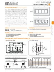
VAV | RETROFIT/BYPASS TERMINAL UNITSKLB | BYPASSKLB UNIT WITH PNEUMATIC CONTROLS DIMENSIONAL INFORMATION▼ KLB UNIT WITH PNEUMATIC CONTROLS, PLAN & SIDE VIEWSACTUATORRETROFIT/BYPASS TERMINAL UNITS6 1/4"(159)CGOUTLETSIDE VIEWFBBYPASSEINLETDOUTLETBYPASSPLAN VIEWREVERSE ACTINGINLETAIRFLOWBBAOUTLETINLETAIRFLOWPLAN VIEWDIRECT ACTING▼ KLB UNIT WITH PNEUMATIC CONTROLS, DIMENSIONAL DETAILSUnitSizeMax CFM[L/s]A B C D E F G6 500 [236] 12 7/8" (327) 7 1/8" (182) 11 1/8" (283) 5 7/8" (149) 4 1/4" (108) 12 3/8" (314) 5 9/16" (141)8 900 [425] 12 7/8" (327) 7 1/8" (182) 11 1/8" (283) 7 7/8" (200) 5 1/4" (133) 12 3/8" (314) 5 9/16" (141)10 1300 [614] 14 7/8" (378) 8 1/8" (210) 13 1/8" (333) 9 7/8" (251) 6 1/4" (159) 14 3/8" (365) 6 9/16" (167)12 2000 [944] 18 7/8" (479) 10 1/8" (257) 17 1/8" (435) 11 7/8" (302) 7 1/4" (184) 18 3/8" (467) 8 9/16" (217)14 2500 [1180] 18 7/8" (479) 10 1/8" (257) 17 1/8" (435) 13 7/8" (352) 8 1/4" (210) 18 3/8" (467) 8 9/16" (217)16 3600 [1699] 22 7/8" (581) 12 1/8" (308) 21 1/8" (537) 15 7/8" (403) 9 1/4" (235) 22 3/8" (568) 10 9/16" (268)18 4400 [2077] 22 7/8" (581) 12 1/8" (308) 21 1/8" (537) 17 7/8" (454) 10 1/4" (260) 22 3/8" (568) 10 9/16" (268)► Dimensions in ( ) are mm. ‘D’ dimension is diameter of inlet, <strong>bypass</strong>, and outlet connections.Unit may be jobsite rotated 180˚ to have controls located on the bottom of the unit.KLBKLB UNIT WITH PNEUMATIC CONTROLS FEATURES & OPTIONS▼ STANDARD FEATURES• 20 Gage Galvanized Steel Casing Construction• 1/2” Thick Dual Density Fiberglass InsulationMeeting NFPA 90A and UL 181 Safety Requirements• Bypass Discharge Collar• Outlet Discharge Collar• 5-10 psi Spring Range Actuator• Balancing Damper Operates on a 0-20 psiThermostat Signal▼ OPTIONAL FEATURES• Manual Inlet Damper• Manual Bypass Damper• Hanger Brackets• Thermostat© KRUEGER 2006E-12 Excellence in Air Distributionwww.krueger-hvac.com
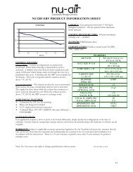
VAV | RETROFIT/BYPASS TERMINAL UNITSKLB | BYPASSKLB UNIT WITH ELECTRIC CONTROLS DIMENSIONAL INFORMATION▼ KLB UNIT WITH ELECTRIC CONTROLS, PLAN & SIDE VIEWSBDFBBYPASSBINLETOUTLETCONTROLENCLOSUREINLETOUTLETGERETROFIT/BYPASS TERMINAL UNITSAC4 1/4" (108)PLAN VIEWSIDE VIEW▼ KLB UNIT WITH ELECTRIC CONTROLS, DIMENSIONAL DETAILSUnitSizeMax CFM[L/s]A B C D E F G6 500 [236] 12 7/8" (327) 7 1/8" (182) 11 1/8" (283) 5 7/8" (149) 4 1/4" (108) 12 3/8" (314) 5 9/16" (141)8 900 [425] 12 7/8" (327) 7 1/8" (182) 11 1/8" (283) 7 7/8" (200) 5 1/4" (133) 12 3/8" (314) 5 9/16" (141)10 1300 [614] 14 7/8" (378) 8 1/8" (210) 13 1/8" (333) 9 7/8" (251) 6 1/4" (159) 14 3/8" (365) 6 9/16" (167)12 2000 [944] 18 7/8" (479) 10 1/8" (257) 17 1/8" (435) 11 7/8" (302) 7 1/4" (184) 18 3/8" (467) 8 9/16" (217)14 2500 [1180] 18 7/8" (479) 10 1/8" (257) 17 1/8" (435) 13 7/8" (352) 8 1/4" (210) 18 3/8" (467) 8 9/16" (217)16 3600 [1699] 22 7/8" (581) 12 1/8" (308) 21 1/8" (537) 15 7/8" (403) 9 1/4" (235) 22 3/8" (568) 10 9/16" (268)18 4400 [2077] 22 7/8" (581) 12 1/8" (308) 21 1/8" (537) 17 7/8" (454) 10 1/4" (260) 22 3/8" (568) 10 9/16" (268)► Dimensions in ( ) are mm. ‘D’ dimension is diameter of inlet, <strong>bypass</strong>, and outlet connections.Unit may be jobsite rotated 180˚ to have controls located on the bottom of the unit.KLB UNIT WITH ELECTRIC CONTROLS FEATURES & OPTIONS▼ STANDARD FEATURES• 20 Gage Galvanized Steel Casing Construction• 1/2” Thick Dual Density Fiberglass InsulationMeeting NFPA 90A and UL 181 Safety Requirements• Bypass Collar• Round Discharge to Room• 24 VAC Actuator▼ OPTIONAL FEATURES• Manual Inlet Damper• Manual Bypass Damper• Balancing Damper• Hanger brackets• Thermostat• 24 Volt Transformer© KRUEGER 2006KLBwww.krueger-hvac.comExcellence in Air DistributionE-13
VAV | RETROFIT/BYPASS TERMINAL UNITSKLB | BYPASSKLB PERFORMANCE DATARETROFIT/BYPASS TERMINAL UNITS▼ KLB, DISCHARGE & RADIATED SOUND DATAUnitSize681012141618Discharge SoundRadiated Sound0.5" ∆ Ps0.5" ∆ PsFlow RateMin ∆ PsOctave Band Lp Min ∆PsOctave Band LpSound Power, LwSound Power, LwCFM (L/s) "WG (Pa) 2 3 4 5 6 7 NC "WG (Pa) 2 3 4 5 6 7 NC200 (94) 0.004 (1.0) 34 31 29 23 18 - - 0.069 (17.2) 48 41 37 37 30 20 -300 (142) 0.009 (2.2) 46 42 39 35 30 23 - 0.155 (38.6) 59 52 49 49 43 34 23400 (189) 0.016 (4.0) 54 51 47 43 39 33 - 0.276 (68.6) 67 60 57 57 52 44 32500 (236) 0.025 (6.2) 61 57 53 49 45 41 - 0.431 (107.3) 73 67 63 64 59 51 39300 (142) 0.003 (0.7) 31 28 25 20 16 - - 0.049 (12.2) 44 36 32 30 24 14 -500 (236) 0.008 (2.0) 46 42 38 35 31 26 - 0.136 (33.8) 58 50 47 45 40 31 21700 (330) 0.016 (4.0) 55 51 47 44 41 37 - 0.266 (66.3) 67 60 56 55 50 42 31900 (425) 0.026 (6.6) 63 58 54 52 48 45 - 0.440 (109.6) 74 67 64 62 58 51 40500 (236) 0.003 (0.8) 34 31 27 24 20 13 - 0.056 (13.9) 46 37 34 31 25 16 -700 (330) 0.006 (1.5) 44 40 36 34 30 25 - 0.109 (27.2) 55 47 43 41 36 27 -1000 (472) 0.013 (3.1) 54 50 46 44 41 37 - 0.223 (55.5) 65 57 54 51 47 39 281300 (614) 0.021 (5.3) 62 57 53 51 48 46 - 0.377 (93.8) 72 64 61 59 55 48 38800 (378) 0.004 (1.0) 38 34 30 29 25 19 - 0.069 (17.1) 43 34 30 27 21 11 -1200 (566) 0.009 (2.2) 50 45 41 40 37 34 - 0.155 (38.6) 57 49 45 42 38 29 -1600 (755) 0.016 (4.0) 58 53 49 48 46 44 - 0.275 (68.5) 68 60 56 53 50 41 322000 (944) 0.025 (6.2) 65 59 55 54 52 52 21 0.430 (107.1) 76 68 65 61 59 51 421000 (472) 0.003 (0.8) 36 32 28 27 24 19 - 0.061 (15.1) 47 37 34 30 25 16 -1500 (708) 0.008 (1.9) 48 43 39 39 36 33 - 0.136 (34.0) 58 49 46 41 38 29 -2000 (944) 0.013 (3.3) 57 52 47 47 45 43 - 0.243 (60.4) 66 57 54 50 47 39 302500 (1180) 0.021 (5.2) 63 58 53 53 51 51 - 0.379 (94.3) 72 63 61 56 54 46 381200 (566) 0.003 (0.7) 35 31 26 26 23 18 - 0.049 (12.2) 45 35 32 26 22 12 -1800 (849) 0.006 (1.6) 47 42 37 37 35 32 - 0.110 (27.4) 56 46 43 38 34 26 -2700 (1274) 0.014 (3.6) 58 53 48 49 47 46 - 0.248 (61.7) 67 58 55 50 47 40 313600 (1699) 0.025 (6.3) 67 61 56 57 56 56 24 0.440 (109.6) 75 66 63 58 56 49 411600 (755) 0.003 (0.8) 37 33 28 28 26 21 - 0.054 (13.5) 38 36 33 27 23 14 -2400 (1133) 0.007 (1.8) 49 44 39 40 38 35 - 0.122 (30.3) 53 48 45 39 36 28 -3200 (1510) 0.013 (3.1) 57 52 47 48 46 46 - 0.217 (54.0) 64 56 53 47 45 37 274400 (2077) 0.024 (5.9) 66 60 55 57 56 57 23 0.410 (102.0) 76 65 62 57 55 48 43► All sound data is based on tests conducted in accordance with ARI 880-98. ∆Ps is the difference in static pressure from inlet to discharge.Sound power levels are in dB, re 10 -12 watts. Discharge sound power is the sound emitted from the unit discharge. Radiated sound power isthe sound emitted from the unit casing. NC application data is from ARI Standard 885-98 Appendix E, as a function of fl ow rate shown. Dash(-) indicates a NC less than 20. Minimum Ps for discharge sound has damper full open for 100% discharge. Minimum Ps for radiated soundhas damper full closed for 100% <strong>bypass</strong>. See Engineering section for reductions and defi nitions.KLB CONTROL INFORMATIONThe following list of standard control arrangements are availablewith the KLB product offering. Each control approach offerspressure dependent, variable air volume, control to thezone. Control functions are identifi ed by the Krueger controlpackage designation.▼ PNEUMATIC CONTROL ARRANGEMENTSEach control arrangement includes a factory supplied and installedpneumatic actuator.▼ ELECTRIC CONTROL ARRANGEMENTPressure dependent control package consists of a 24 volt electricactuator, optional 24 volt transformer and a control enclosure.3500 - Temperature Responsive Control1600 - Actuator Only; DA-NC Pressure Dependent Control1601 - Actuator Only; RA-NO Pressure Dependent ControlKLBPneumatic Control Legend:DA - Direct Acting ThermostatRA - Reverse Acting ThermostatNO - Normally Open Damper Position to the ZoneNC - Normally Closed Damper Position to the Zone© KRUEGER 2006E-14 Excellence in Air Distributionwww.krueger-hvac.com
VAV | RETROFIT/BYPASS TERMINAL UNITSKLB | BYPASSKLB SUGGESTED SPECIFICATION & CONFIGURATION1. SERIES: (XXX)KLB - Bypass Terminal UnitKLB UNITFurnish and install Krueger model KLB <strong>bypass</strong> <strong>terminal</strong> <strong>units</strong>of the sizes shown in the plans.2. SENSOR TYPE: (X)0 - No Sensor3. UNIT STYLE: (X)0 - Standard KLB1 - KLB with Multiple Outlets4. INLET CODE: (XX)06 - 6”08 - 8”10 - 10”12 - 12”14 - 14”16 - 16”18 - 18”5. CONTROL TYPE: (XXXX)1600 - DA/NC Pneumatic1601 - RA/NO Pneumatic3500 - Electric6. UNIT ACCESSORIES: (X) (X) (X) (X)0 - NoneS - Hanger BracketsC - Damper, Manual InletD - Damper, Manual - One for each multiple outletE - Damper, Manual BypassG - 24-24 Vac TransformerH - 120-24 Vac TransformerJ - 208-24 Vac TransformerK - 240-24 Vac TransformerL - 277-24 Vac TransformerUnit casing shall be constructed of not less than 20 gage galvanizedsteel. All air inlet/outlet collars shall accommodatestandard spiral and fl ex duct sizes.Controls must be capable of being located on top or bottom ofunit casing.Unit casing shall be lined with 1/2” thick, 1 1/2 lb. dual densityfi berglass insulation that meets UL 181 and NFPA 90A.The radiated and discharge attenuation factors for the specified NC levels shall be based on attenuation factors from ARIStandard 885-98 Appendix E, which includes room absorption,environmental adjustment factor, duct insertion, end reflection and duct branching.Label information shall be adhered to each unit to include modelsize, airfl ow (CFM), and tagging information.Terminals shall be tested in accordance with the latest ARIStandard 880.RETROFIT/BYPASS TERMINAL UNITS© KRUEGER 2006SAMPLE CONFIGURATION: KLB - 0 - 0 - 08 - 1600 - S - 0 - 0 - 0KLBwww.krueger-hvac.comExcellence in Air DistributionE-15