
Create successful ePaper yourself
Turn your PDF publications into a flip-book with our unique Google optimized e-Paper software.
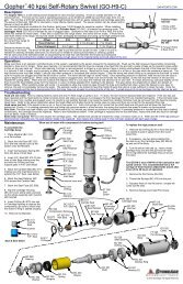
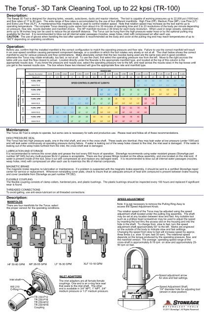
®The Torus - 3D Tank Cleaning <strong>Tool</strong>, up to 22 kpsi (<strong>TR</strong>-100)Description:The Torus 3D <strong>Tool</strong> is designed for cleaning tanks, vessels, autoclaves, ducts and reactor interiors. The tool is capable of working pressures up to 22,000 psi (1500 bar)and flow rates of 17 to 80 gpm. The wide range of flow rates is accomodated by the use of four different manifolds: High Flow (HF), Medium Flow (MF), Low Flow (LF)and Extra Low Flow (XLF). A maintenance-free magnetic brake is used to control rotation speed. Note that rotation speed may increase as the tool warms up tooperating temperature. The complete Torus cleaning cycle varies from about 4 to 30 minutes of operating time and 3 to 23 revolutions of the body per minute dependingon pressure, flow rate, nozzle diameter and manifold choice. The HP manifold revolves 2.36 times for each body revolution. When used in large vessels, extensionarms up to 36 inches long can be used to reduce the jet standoff distance. The Torus can be hung from the high pressure water hose or by the optional pulling ringavailable for the tool. It is recommended to blow out all internal water passages (nozzles, weep holes, inlet) with compressed air after each use.CAUTION: The use of gloves when handling the tool after operation is recommended as the body and cover at the pulling ring end may reach temperatures of up to160°F depending on operating conditions.Operation:Before use, confirm that the installed manifold is the correct configuration to match the operating pressure and flow rate. Failure to use the correct manifold will resultin an over-speed condition causing permanent component damage, or a condition in which the tool rotates very slowly or not at all. The chart below shows the correctmanifold to use for various pressure and flow combinations. Make absolutely certain that the two nozzles being used are the same size and in good condition,otherwise the Torus may rotate erratically, too fast, or not at all. To use the chart, first select the operating pressure row from the left. Move to the right accross thetable until you read the flow closest to actual. Located directly under the flowrate is the appropriate manifold type, and located at the top of this column is theappropriate nozzle size. If you know the pressure and nozzle size, select the operating pressure row to the left, and read across the nozzle sizes in the top boxes untilyou get to the nearest nozzle size. The box where these two intersect will give the appropriate flow rate and manifold type.PRESSURE, PSI20,000 15,000 10,000 5,000 2,000NOZZLE SIZENozzle Diameter 0.035 0.038 0.042 0.047 0.052 0.057 0.063 0.069 0.075 0.082 0.090 0.098 0.106 0.115 0.125 0.135 0.145 0.155 0.165Nozzle # 2 2.5 3 4 5 5.5 6.5 8 10 12 14 16 19 23 27 31 36 41 46FLOW, GPMSPEED CON<strong>TR</strong>OL IS LIMITED AT 2,000 PSI26 30 34 39 43 47 51MANIFOLD XLF XLF XLF XLF XLF XLF XLFFLOW, GPM 18 22 26 30 35 41 47 54 61 68 75MANIFOLD XLF XLF XLF LF LF LF LF MF MF MF MFFLOW, GPM 12 15 17 22 26 30 36 42 50 57 66 76MANIFOLD XLF XLF XLF LF LF LF MF MF MF MF HF HFFLOW, GPM 10 12 15 18 21 27 31 37 44 52 61 70 81MANIFOLD XLF XLF XLF LF LF LF MF MF MF HF HF HF HFFLOW, GPM 10 11 13 17 20 24 30 36 42 51 60 70 81MANIFOLD XLF XLF XLF LF LF LF MF MF MF HF HF HF HFMaintenance:The Torus 3D <strong>Tool</strong> is simple to operate, but some care is necessary for safe and productive use. Please read and follow all of these recommendations.HIGH PRESSURE SEALThe Torus has two high pressure seals, one in the inlet shaft, and one in the cross shaft. These seals are identical; they may leak water at low pressure (under 1000 psi)and will leak water continuously at operating pressure during failure. If water is leaking out of the weep holes closest to the inlet, the inlet seal is damaged. If the water isleaking out of the weep holes furthest from the inlet, the cross-shaft seal is damaged.LUBRICATION AND STORAGEIt is recommended to remove the cover plate and grease the tool every 500 hours of operation. StoneAge recommends using water resistant grease (StoneAge partnumber GP 045) but any multi-purpose NLGI 2 grease is acceptable. There are four grease fittings located on the elbow assembly, and one located on the inlet end. Ifwater is present inside of the tool, blow it out with compressed air and replace any damaged seals. It is recommended to blow out all internal water passages (nozzles,weep holes, inlet) with compressed air after each use to maximize the life of internal componets.MAGNETIC BRAKEThe magnetic brake requires no lubrication or maintanence. If a problem is suspected with the magnetic brake assembly, it should be sent to a certified StoneAge repaircenter for service or replacement. Whenever reinstalling cover plate, check to insure that an adequate amount of heat sink compound is present between brake housingand cover (available from StoneAge as part number <strong>TR</strong> 282).FLEXIBLE COUPLINGThe flexible coupling consists of clamp collars, hardened pins, and plastic bushings. The plastic bushings should be inspected every 100 hours and replaced if significantwear is found.THREADED CONNECTIONSTo avoid galling, use anti-sieze lubricant on all threaded connections.Description:MANIFOLDSThere are four manifolds for the Torus; selectthe proper version for the operating conditions.SPEED ADJUSTMENTNote: It is not necessary to remove the Pulling Ring Assy toaccess the Speed Adjustment Knob.The rotation speed of the Torus may be adjusted using the speedadjustment shaft located under the pulling ring assembly. The shaftmay be set at any location between slow and fast. Any suitable toolsuch as a phillips head screwdriver may be used to adjust the speedby inserting the tool thru the access slot on the housing and into thehole in the shaft. To change from slow to fast, turn the speedadjustment shaft approximately 50° to the left. Marks are engravedon the outside of the body to indicate slow and fast setttings.Changing the speed from slow to fast will increase speed by approx.three times (i.e. slow 10 rpm; fast 30 rpm). The rotational speeddepends on the torque produced by the operating pressure, flow, andthe manifold version. The average operating speed range of thecross-shaft is approximately 8-16 rpm on slow and approximately 25-50 rpm on fast.HF 50-80 GPMMF 28-55 GPMLF 16-30 GPMXLF 10-18 GPMInlet shaftWS 210O-RingINLET ADAPTERSThe inlet adapters are all female-femalecouplings. One end is an o-ring face sealthat seals to the inlet shaft. The otherend is available in 3/4" NPT, 1" NPT, 3/4"medium pressure or 1.0" medium pressure.Speed adjustment arrowfor slow and fast settings.Speed Adjustment Shaft,1/4" diameter hole for adjusting tool(shown in slow position)<strong>TR</strong> 230-P12<strong>TR</strong> 230-P16<strong>TR</strong> 230-M12<strong>TR</strong> 230-M16Coupling®© 2011 StoneAge , All Rights Reserved
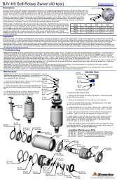
The Torus, 3-D Tank Cleaning<strong>Tool</strong><strong>TR</strong>-100 ASSEMBLYHC 090PULLING RING<strong>TR</strong> 152INSERT, PULLING RINGGB 337-12HEX BOLT .37-16 X 3.00 SS<strong>TR</strong> 200BRAKE ASSEMBLY(6) <strong>TR</strong> 116SEALING SCREWSBHCS .31-18 X .50 SS<strong>TR</strong> 220COUPLING ASSEMBLY<strong>TR</strong> 170CROSS SHAFT ASSEMBLYGN 337-LNUT, HEX LOCK SS <strong>TR</strong> 121PLATE,COVER(6) <strong>TR</strong> 115SEALING SCREWSHBCS .19-24 X .38 SS<strong>TR</strong> 102BODY WELDMENT<strong>TR</strong> 240-HF<strong>TR</strong> 240-MF<strong>TR</strong> 240-LF<strong>TR</strong> 240-XLFMANIFOLD ASSEMBLY<strong>TR</strong> 120INLET ASSEMBLY<strong>TR</strong> 130ELBOW ASSEMBLY<strong>TR</strong> 230-M16<strong>TR</strong> 230-M12<strong>TR</strong> 230-P16<strong>TR</strong> 230-P12COUPLING, O-RING FACE<strong>TR</strong> 107O-RING , COVER PLATE<strong>TR</strong> 250SHAFT CAPGS 319-015SHCS .19-24 X .38 SS<strong>TR</strong> 240-XX MANIFOLD ASSEMBLY<strong>TR</strong> 577-XXNIPPLE ASSEMBLY<strong>TR</strong> 120 INLET ASSEMBLYFS 004-0-SSZERK, S<strong>TR</strong>AIGHT<strong>TR</strong> 103END INLET<strong>TR</strong> 113SEAL(2) <strong>TR</strong> 247SOCKET HEAD CAP SCREWspring side in<strong>TR</strong> 118RETAINING RING(2) <strong>TR</strong> 260-HF(2) <strong>TR</strong> 260-MF(2) <strong>TR</strong> 260-LF(2) <strong>TR</strong> 260-XLFHALF MANIFOLD<strong>TR</strong> 245SEAL, HP MANIFOLD(2) BJ 007BEARINGSA 059O-RING<strong>TR</strong> 577.3FLOW S<strong>TR</strong>AIGHTENERHC 012-TOHP SEAL AND O-RING<strong>TR</strong> 122 INLET SHAFTWS 210O-RING(2) AP4-XXXNOZZLE<strong>TR</strong> 104GEAR, INLET SHAFTwide outer racewide inner race<strong>TR</strong> 124LOCK NUT<strong>TR</strong> 105O-RING, INLET END(4) <strong>TR</strong> 117SEALING SCREWSHCS .37-16 X 1.25 SSCJ 009BEARING<strong>TR</strong> 172CROSS SHAFTMJ 011-CSEATMJ 011-CSEATHC 012-TOHP SEAL AND O-RINGBJ 007BEARINGwide outer raceFS 004-45-SSZERK, 45°<strong>TR</strong> 170 CROSS SHAFT ASSEMBLY(2) FS 004-0-SSZERK, S<strong>TR</strong>AIGHT(4) GS 337-03SHCS .375-16 X .75 SS<strong>TR</strong> 126GEAR, BEVEL 27Tspring side in<strong>TR</strong> 118RETAINING RING<strong>TR</strong> 250SHAFT CAP<strong>TR</strong> 220 COUPLING ASSEMBLY<strong>TR</strong> 221COLLAR ASSEMBLY<strong>TR</strong> 173CAP, OUTLET<strong>TR</strong> 175O-RING(2) GS 319-015SHCS .19-24 X .38<strong>TR</strong> 223BUSHING, PEEK<strong>TR</strong> 222DOWEL PIN<strong>TR</strong> 113SEAL®© 2011 StoneAge , All Rights Reserved
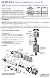
The Torus, 3-D Tank Cleaning <strong>Tool</strong><strong>TR</strong> 130 ELBOW ASSEMBLY<strong>TR</strong> 135NEEDLE BEARING(2) <strong>TR</strong> 138 RETAINING RING(2) <strong>TR</strong> 134 SEALFS 004-0-SSZERK, S<strong>TR</strong>AIGHTopen side ofseal towardselbow<strong>TR</strong> 140GEAR 8T<strong>TR</strong> 144GEAR, BEVEL 18T<strong>TR</strong> 139GEAR 23Topen side ofseal towardselbow(2) <strong>TR</strong> 143KEY, PRIMARY SHAFT<strong>TR</strong> 131PRIMARY SHAFT<strong>TR</strong> 146RETAINING RING<strong>TR</strong> 132ELBOW(4) <strong>TR</strong> 127O-RING(2) <strong>TR</strong> 142KEY, PINION SHAFT<strong>TR</strong> 133GEAR 21T(2) <strong>TR</strong> 136NEEDLE BEARING(2) GP 025-P4PLUG, P4<strong>TR</strong> 141WASHER, PINION SHAFTDT 032RETAINING RING<strong>TR</strong> 145BEARINGGS 325-02SHCS .25-20 X .50 SS<strong>TR</strong> 200 BRAKE ASSEMBLY<strong>TR</strong> 212O-RING<strong>TR</strong> 202PLATE, BASE(2) <strong>TR</strong> 210MAGNET ASSEMBLYRJ 009BEARING(8) GS 313-02SHCS .13-32 X .50 SS<strong>TR</strong> 205SHAFT, BRAKEspring side<strong>TR</strong> 201PLANETARY GEARBOXRJ 010SEALGC 313-025SHCS .13-32 X .62 SSkey not required<strong>TR</strong> 215O-RING<strong>TR</strong> 206SHAFT, SPEED CON<strong>TR</strong>OL(2) <strong>TR</strong> 208SHOULDER BOLT(2) <strong>TR</strong> 214WAVE SPRING<strong>TR</strong> 211O-RINGGN 337-LLOCKNUT<strong>TR</strong> 207DISC, CU <strong>TR</strong> 203COVER, BRAKEGS 319-08SHCS .19-24 X 2.0 SSGP 025-P4PLUG, P4<strong>TR</strong> 204PLATE, STOP<strong>TR</strong> 213WAVE SPRINGTORUS INSTALLATION IN <strong>TR</strong> 408-SS CAGEOne set of ribs on the cagehave a slightly larger gapwhich allows easier installationof the Torus into the cage.Insure that the end plate of the cage is installedas shown over the Pulling Ring Housing andNOT over the <strong>Insert</strong>; otherwise the Torus willnot rotate correctly during operation.Pulling Ring HousingNote that the short2" nipples must beinstalled when usingthe Torus in the cage.Pulling Ring <strong>Insert</strong>®© 2011 StoneAge , All Rights Reserved
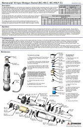
Torus 3D <strong>Tool</strong><strong>TR</strong>-100 HIGH PRESSURE SEAL MAINTENANCEThe Torus has 2 high pressure seals. These seals may leak attap pressure, but should seal at pressures above 1000 psi.(2) SHCS<strong>TR</strong> 250 Shaft CapH.P. Half Manifolds(2) <strong>TR</strong> 247SHCS<strong>TR</strong> 121 Cover Plate(6) <strong>TR</strong> 115 Sealing BHCSTo access the Torus internals:1. Remove the (2) Socket Head Cap Screwsholding the Shaft Cap (<strong>TR</strong> 250) in place. Loosenthe (2) Socket Head Cap Screws (<strong>TR</strong> 247) on theHigh Pressure Half Manifolds & slip the Manifoldsoff the Cross Shaft.2. Remove the (6) Sealing Button Head CapScrews (<strong>TR</strong> 115) from the Cover Plate (<strong>TR</strong> 121)and remove the Cover Plate.To access the Inlet Shaft Seal:! SEE CAUTION !1. Remove the (4) Sealing Socket Head CapScrews holding the Inlet Assy (<strong>TR</strong> 120) to theBody and the Elbow Assy. The Inlet Assy maythen be slid out of the Elbow Assy to gain accessto the Seal. The Seal is located in the end of theInlet Shaft. No more disassembly is required.MJ 011-C Seat(4) SHCSTo access the Cross Shaft Seal:1. Remove the (4) Socket Head Cap Screws thathold the Cross Shaft Assy to the Elbow Assy. Liftthe Cross Shaft Assy out of the Main Elbow. TheSeal is located in the end of the Cross Shaft. Nomore disassembly is required.HC 012-TOH.P. Seal & O-Ring<strong>TR</strong> 170Cross Shaft AssyHC 012-TOH.P. Seal & O-RingMJ 011-C SeatElbow AssyTo maintain H.P. Seat & Seal:1. Remove the Carbide Seat (MJ 011-C) andthe H.P. Seal (HC 012-TO). Inspect the Seatfor chips on edges. Replace if damaged.Inspect the related face of the Elbow Assy fordings or pits. If damaged, it must be faced orreplaced, otherwise the Seal will leak.2. Apply grease to new H.P. Seal and installinto bore. Place the Seat on the Seal with theflat side against the Seal. The chamfered sideshould face towards the Elbow Assy.chamfered face(4) Sealing SHCS<strong>TR</strong> 120 Inlet Assy! CAUTION !: The use of gloves when handling thetool after operation is recommended as the body and Bodycover at the pulling ring end may reach temperaturesof up to 160°F depending on operating conditions. ! SEE CAUTION !MJ 011-CCarbide Seatflat facetowards sealHC 012-TOH.P. Seal & O-Ring<strong>TR</strong>-100 ASSEMBLY SEQUENCE & DETAILSNote: Always use anti-sieze lubricanton all threaded connections toprevent galling.1. Apply heat-conducting grease(StoneAge part number <strong>TR</strong> 282) tobottom surface of Brake Assy (thesurface that will be in contact with theinside bottom of the Body) and insertBrake Assy into Body by first tilting andinserting under web of Body and thensliding forward as shown; use care toinsure that the Speed Adjust Knob withO-Ring starts into the hole in the end ofthe Body while sliding the Assy forward.Loosely start (2) Sealing Button HeadCap Screws thru bottom of Body andinto Brake Assy.BrakeBodyAssy2. <strong>Insert</strong> Elbow Assy (may include Cross Shaft Assy) intoBody and loosely start (4) Sealing Button Head Cap Screwsthru bottom of Body and into Elbow.Elbow Assy(4) SealingSHCSInlet Assy(4) Elbow Sealing BHCSPulling RingAssy5. Apply heat-conducting grease(StoneAge part number <strong>TR</strong> 282) to topsurface of Brake Assy and install theCover Plate using (6) Sealing ButtonHead Cap Screws. Take care to insurethe O-Ring is properly seated in thegroove of the Cover Plate.6. Install the H.P. Manifolds onto theCross Shaft and hand tighten the (2) largeSocket Head Cap Screws.7. Install the Shaft Cap using (2) smallSocket Head Cap Screws and tightenthem to 24 in/lbs. Then tighten the (2)large Cap Screws on the H.P. Manifoldsto 50 ft/lbs.Hex Bolt & Hex Lock NutBrake Assy top surface(2) BrakeSealing BHCSstart shaftinto hole3. <strong>Insert</strong> Inlet Assy into end of Body and tighten (4)Sealing Socket Head Cap Screws thru end of Body andinto Elbow. Take care to insure O-Ring is properlyseated in groove. Next, tighten the (4) Sealing ButtonHead Cap Screws at the bottom of the Body into theElbow Assy.Cover Plate4. Once the Elbow Assy is firmly mounted and the Brake Assy is loosely in place, the (2) Coupling Assys needto be installed. Note that keys are NOT required in the shafts. The easiest way to install the Couplings are tocouple (1) Male Half and (1) Female Half together, place a rag in the bottom of the Body cavity under wherethe couplings are to be, and slip them into place underneath the bottom of the shafts (resting on top of the rag).The rag will help hold them in place and up against the shafts while starting the Socket Head Cap Screws inthe opposite pair of Coupling Halves. Note that there should be a .03" gap between the Elbow and theCoupling face abutting the Elbow. Tighten the (2) Elbow Coupling screws evenly to 50 in/lbs. Next, allow a.03" gap between the Elbow Coupling and the Brake Coupling as shown. Tighten the (2) Brake Couplingscrews to 50 in/lbs. Finally, tighten the (2) remaining Sealing Button Head Cap Screws holding the Brake Assyto the Body. Also grease the (4) Zerks on the Elbow if necessary.H.P. ManifoldsGrease ZerksGrease ZerksShaftCap8. Finally, install the Pulling RingAssy onto the Body with the Hex Boltand Hex Lock Nut.MaleCoupling HalfFemaleCoupling HalfNote: It is not necessary to removethe Pulling Ring Assy to access theSpeed Adjustment Shaft.Elbow Coupling.03 gap.03 gapBrake Coupling®© 2011 StoneAge , All Rights Reserved