

STT173 - Honeywell
STT173 - Honeywell
STT173 - Honeywell

Create successful ePaper yourself
Turn your PDF publications into a flip-book with our unique Google optimized e-Paper software.
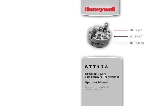
UKFRDEPage 1Page 7Seite 13<strong>STT173</strong>STT3000 SmartTemperature TransmitterOperator ManualDoc. No.: 34-ST-25-26Revision Date: 2/06
Copyright, Notices, and Trademarks© Copyright 2006 by <strong>Honeywell</strong> Inc.Revision 0 – 2/06While this information is presented in good faith andbelieved to be accurate, <strong>Honeywell</strong> disclaims theimplied warranties of merchantability and fitness for aparticular purpose and makes no express warrantiesexcept as may be stated in its written agreement withand for its customer.In no event is <strong>Honeywell</strong> liable to anyone for anyindirect, special or consequential damages. Theinformation and specifications in this document aresubject to change without notice.<strong>Honeywell</strong> International, Inc.Industrial Measurement and Control2500 W. Union Hills DrivePhoenix, Arizona 850272/06 <strong>STT173</strong> Smart Temperature Transmitter Operator Manual i
About This DocumentAbstractThis document is intended to support the installation and operation ofthe Model <strong>STT173</strong> Smart Temperature Transmitter.Revision NotesThe following list provides notes concerning all revisions of thisdocument.Rev. ID Date Notes0 2/06 This document is the initial <strong>Honeywell</strong>release of the <strong>STT173</strong> TransmitterContactsWorld Wide WebThe following lists <strong>Honeywell</strong>’s World Wide Web sites that will be ofinterest to our customers.<strong>Honeywell</strong> Organization WWW Address (URL)Corporatehttp://www.honeywell.comIndustrial Measurement and Control http://www.honeywell.com/imcTelephoneContact us by telephone at the numbers listed below.Organization Phone NumberUnited States and <strong>Honeywell</strong> 1-800-423-9883 Tech. SupportCanada 1-888-423-9883 Q&A Faxback(TACFACS)1-800-525-7439 ServiceNoticesSafety InstructionsEx installation:For safe installation of <strong>STT173</strong> in a hazardous area, the followingmust be observed. The module must only be installed by qualifiedpersonnel who are familiar with the national and international laws,directives and standards that apply to this area.Year of manufacture can be taken from the first two digits in the serialnumber.For installlation requirements and Ex data see section 4.3 ATEXInstallation Data and the ATEX certificate.Consigne de sécuritéInstallation S.I. :Pour l’installation de <strong>STT173</strong> dans les zones dangereuses,conformez-vous aux consignes de sécurité suivantes : l’installationne doit être réalisée que par du personnel qualifié connaissant lalégislation nationale et internationale ainsi que les directives etstandards régissant ce domaine.L’année de production ressort des deux premiers chiffres du numérode série.Pour les conditions d’installation et les données de sécurité intrinsèque,voir section 4.3 ATEX Installation Data et le certificat ATEX.SicherheitsinstruktionEx-Installation:Für sichere Installation von <strong>STT173</strong> in explosionsgefährdeterUmgebung muss folgendes beobachtet werden. Die Installationmuss nur von qualifizierten Personen, die mit den nationalen undinternationalen Gesetze, Direktiven und Standards des Gebietsbekannt sind, vorgenommen werden.Die ersten beiden Ziffern der Seriennummer geben dasProduktionsjahr an.Für Einbauvorschriften und Ex-Daten siehe Abschnitt 4.3 ATEXInstallation Data und das ATEX-Zertifikat.ii <strong>STT173</strong> Smart Temperature Transmitter Operator Manual 2/06 2/06 <strong>STT173</strong> Smart Temperature Transmitter Operator Manual iii
CONTENTS1. 2-WIRE PROGRAMMABLETRANSMITTER MODEL <strong>STT173</strong> ........................ 11.1 Features .......................................................... 11.2 Application ...................................................... 11.3 Technical Characteristics ................................ 11.4 Installation ....................................................... 21.5 Electrical Connections .................................... 31.6 Block Diagram ................................................. 41.7 Programming ................................................... 51.8 Mechanical Specifications .............................. 61.9 Mounting of Sensor Wires .............................. 63.8 Abmessungen ................................................. 183.9 Montage von Fühlerleitungen ......................... 184. INSTALLATION DRAWINGS ................................ 194.1 FM Installation Drawing 50016324 ................. 194.1.1 Model STT171-BS and <strong>STT173</strong>-BS ...... 194.1.2 The Entity Concept ................................ 204.2 CSA Installation Drawing 50016326 ............... 214.2.1 Model STT171-BS, <strong>STT173</strong>-BSand STT17H-BS ..................................... 214.3 ATEX Installation Data ..................................... 235. DECLARATION OF CONFORMITY ..................... 242. TRANSMETTEUR 2-FILSPROGRAMMABLE <strong>STT173</strong> ................................. 72.1 Caractères ....................................................... 72.2 Application ...................................................... 72.3 Caractéristiques techniques ........................... 72.4 Installation ....................................................... 82.5 Connexions ..................................................... 92.6 Schema de Principe ........................................ 102.7 Programmation ............................................... 112.8 Dimensions mécaniques ................................. 122.9 Montage des fils du capteur ........................... 123. 2-DRAHT PROGRAMMIERBARERMESSUMFORMER <strong>STT173</strong> ................................. 133.1 Das Unterscheidungsmerkmal ........................ 133.2 Verwendung .................................................... 133.3 Technische Merkmale ..................................... 133.4 Installation ....................................................... 143.5 Anschlüsse ...................................................... 153.6 Blockdiagramm ............................................... 163.7 Programmierung ............................................. 17iv <strong>STT173</strong> Smart Temperature Transmitter Operator Manual 2/06 2/06 <strong>STT173</strong> Smart Temperature Transmitter Operator Manual v
FIGURESFigure 1-1 2-Wire installation in Control Room ........ 2Figure 1-2 Electrical Connections ............................. 2Figure 1-3 Block Diagram ......................................... 3Figure 1-4 Programming ........................................... 4Figure 1-5 Mechanical Specifications ....................... 5Figure 1-6 Mounting of Sensor Wires ....................... 6Figure 2-1 Installation 2-fils en sale de contrôle ....... 8Figure 2-2 Connexions .............................................. 8Figure 2-3 Schema de Principe ................................ 9Figure 2-4 Programmation ........................................ 10Figure 2-5 Dimensions mécaniques ......................... 11Figure 2-6 Montage des fils du capteur ................... 12Figure 3-1 2-Draht-Installation .................................. 14Figure 3-2 Anschlüsse .............................................. 14Figure 3-3 Blockdiagramm ....................................... 15Figure 3-4 Programmierung ...................................... 16Figure 3-5 Abmessungen .......................................... 17Figure 3-6 Montage von Fühlerleitungen .................. 18Figure 4-1 Model STT171-BS and <strong>STT173</strong>–BS[FM Installation Drawing] ....................................... 19Figure 4-2 Model STT171-BS, <strong>STT173</strong>-BS andSTT17H-BS [Connections with separatepower supply and receiver] ................................... 21Figure 4-3 Model STT171-BS, <strong>STT173</strong>-BS andSTT17H-BS [Connections with power supplyand barrier built into receiver] ............................... 221. 2-WIRE PROGRAMMABLETRANSMITTER MODEL <strong>STT173</strong>1.1 Features• RTD, TC, Ohm, or mV Input• Extremely high Measurement Accuracy• 1.5 kVAC galvanic isolation• Programmable sensor error value• For DIN form B sensor head mountingEnglish1.2 Application• Linearised temperature measurement with Pt100 or Ni100,or thermocouple sensor.• Conversion of linear resistance variation to a standardanalogue current signal, for instance from valves or Ohmiclevel sensors.• Amplification of a bipolar mV signal to a standard 4-20mA current signal.1.3 Technical Characteristics• Within a few seconds the user can program the <strong>STT173</strong>to measure temperatures within all RTD ranges defined bythe norms.• The RTD and resistance inputs have cable compensationfor 2-, 3-, and 4-wire connection.• Continuous check of vital stored data for safety reasonsvi <strong>STT173</strong> Smart Temperature Transmitter Operator Manual 2/06 2/06 <strong>STT173</strong> Smart Temperature Transmitter Operator Manual 1
+English1.4 Installation1.5 Electrical ConnectionsInput:EnglishRTD, 2-wire RTD, 3-wire RTD, 4-wire TC, internal CJC3 4 5 6 3 4 5 6 3 4 5 6 3 4 5 6-+TC, external CJC3 4 5 6mV3 4 5 6Resistance, 2-wire Resistance, 3-wire3 4 5 6 3 4 5 6-+-+Resistance, 4-wire3 4 5 6Output:2-wire installation1 2mA -Figure 1-1 2-Wire installation in Control RoomFigure 1-2 Electrical Connections2 <strong>STT173</strong> Smart Temperature Transmitter Operator Manual 2/062/06 <strong>STT173</strong> Smart Temperature Transmitter Operator Manual 3
Tag no:3-wire------1.00 secUpscale08:30:00English1.6 Block DiagramEnglish1.7 Programming• STT17C is a communications interface that is needed forprogramming the <strong>STT173</strong>.• For programming, please refer to Figure 1-4 and the helpfunction in STT17C.• STT17C is not approved for communication with modulesinstalled in hazardous (Ex) areas.ORDER: STT17C12BlackDisconnectRed Yellow**GreenReceivingEquipment+VsupplyInput<strong>STT173</strong>ConnectorCOMFile Product Input Output Communication Language OptionDate: 1994-8-10Serial no:943201594STT17CAnalog input Analog outputInput type: Pt100 DIN/IEC Output type: 4 - 20mAInput range: 0.00 - 50.00 C Sensor error:Connection:Cold junction comp:Response time:* Connected only foron-line programmingFigure 1-4 Programming2/06 <strong>STT173</strong> Smart Temperature Transmitter Operator Manual 5mV+mV-RTD, lin. R- wire4 3 2TCExt.CJC+-Input gnd.65Int.CJC43MUXPGAA / DCPUEEPROM<strong>STT173</strong>4 mAComm.D / A0...16mAEx circuit <strong>STT173</strong>12Supply +7.2...35 VDCSupply -mA4...20 mAFigure 1-3 Block Diagram4 <strong>STT173</strong> Smart Temperature Transmitter Operator Manual 2/06
English1.8 Mechanical Specifications+ -2. TRANSMETTEUR 2-FILSPROGRAMMABLE<strong>STT173</strong>Françaised 6 mm33 mm 20.2 mmD 44 mmFigure 1-5 Mechanical Specifications1.9 Mounting of Sensor Wires2.1 Caractères• Entrée RTD, TC, Ohm ou mV• Très grande précision de mesure• Isolation galvanique de 1,5 kVca• Sécurité programmable• Pour tête de sonde DIN B2.2 Application• Mesure linéarisée de la température avec un capteurPt100, Ni100 ou de thermocouples.• Conversion d’une résistance linéaire en un signal courantstandard analogique pour mesurer par exemple le niveauou la position d’une vanne.• Amplification d’un signal mV bipolaire en un signal courantstandard de 4-20 mA.2.3 Caractéristiques techniques• Le <strong>STT173</strong> peut être programmé de manière simple etrapide.• Compensation de ligne pour des entrées RTD etrésistance avec un raccordement à 2, 3 et 4 fils.• Vérification continue des données sauvegardées.Wires must be mounted between the metal platesFigure 1-6 Mounting of Sensor Wires6 <strong>STT173</strong> Smart Temperature Transmitter Operator Manual 2/062/06 <strong>STT173</strong> Smart Temperature Transmitter Operator Manual 7
+Française2.4 Installation2.5 ConnexionsEntrée :RTD, 2-fils RTD, 3-fils RTD, 4-fils TC, CSF interne3 4 5 6 3 4 5 6 3 4 5 6 3 4 5 6Française-+TC, CSF externe3 4 5 6mV3 4 5 6Résistance, 2-fils Résistance, 3-fils3 4 5 6 3 4 5 6-+-+Résistance, 4-fils3 4 5 6Sortie :Installation 2-fils1 2mA -Figure 2-2 ConnexionsFigure 2-1 Installation 2-fils en sale de contrôle8 <strong>STT173</strong> Smart Temperature Transmitter Operator Manual 2/062/06 <strong>STT173</strong> Smart Temperature Transmitter Operator Manual 9
Tag no:3-wire------1.00 secUpscale08:30:00Française2.7 Programmation• STT17C est un kit de programmation permettant deprogrammer le <strong>STT173</strong>.• Pour le raccordement du STT17C, veuillez vous reporterau schéma ci-dessous et à l’aide en ligne du logicielSTT17C.• STT17C ne doit pas être utilisé pour communication avecdes modules installés en zone dangereuse.Française2.6 Schema de PrincipeNuméro de référence: STT17C12NoirDébranchéRouge * Jaune* VerteAPI ou autres+Valim.Entrée<strong>STT173</strong>ConnecteurCOMFile Product Input Output Communication Language OptionDate: 1994-8-10Serial no:943201594STT17CAnalog input Analog outputInput type: Pt100 DIN/IEC Output type: 4 - 20mAInput range: 0.00 - 50.00 C Sensor error:Connection:Cold junction comp:Response time:* Connexion facultativeFigure 2-4 Programmation2/06 <strong>STT173</strong> Smart Temperature Transmitter Operator Manual 11mV+mV-RTD, R. lin.- fils4 3 2CSFext.TC+Entrée masse-65CSFint.43MUXPGAA / DCPUEEPROM<strong>STT173</strong>4 mAComm.D / A0...16mACircuit S.I. <strong>STT173</strong>12Alimentation +7,2...35 VccAlimentation -mA4...20 mAFigure 2-3 Schema de Principe10 <strong>STT173</strong> Smart Temperature Transmitter Operator Manual 2/06
Tag no:3-wire------1.00 secUpscale08:30:00Deutsch3.6 BlockdiagrammDeutsch3.7 Programmierung• STT17C ist eine batteriegespeiste Schnittstelle zurProgrammierung des PRetop <strong>STT173</strong>.• Bezüglich Programmierung verweisen wir auf dienachfolgende Zeichnung und die “Hilfe”-Funktion imSTT17C.• STT17C darf nicht zur Kommunikation mit Modulen, die inEx-gefährdeten Bereichen installiert sind, benutzt werden.Bestellangaben: STT17C12SchwarzUnterbrechenRot Gelb**GrünBetriebsspannung+VBEingang<strong>STT173</strong>AnschlussstelleCOMFile Product Input Output Communication Language OptionDate: 1994-8-10Serial no:943201594STT17CAnalog input Analog outputInput type: Pt100 DIN/IEC Output type: 4 - 20mAInput range: 0.00 - 50.00 C Sensor error:Connection:Cold junction comp:Response time:* Nur anzuschliessen, wenn on-line(im Betrieb) konfiguriert werden soll.Figure 3-4 Programmierung2/06 <strong>STT173</strong> Smart Temperature Transmitter Operator Manual 17mV+mV-WTH, lin. R- Draht4 3 2TEExt.CJC+Eingang Masse-65Int.CJC43MUXPGAA / DCPUEEPROM<strong>STT173</strong>4 mAKomm.D / A0...16mAEx-Kreislauf <strong>STT173</strong>12Versorgung +7,2...35 VDCVersorgung -mA4...20 mAFigure 3-3 Blockdiagramm16 <strong>STT173</strong> Smart Temperature Transmitter Operator Manual 2/06
Deutsch3.8 Abmessungen+ -d 6 mm33 mm 20.2 mmD 44 mmFigure 3-5 Abmessungen3.9 Montage von Fühlerleitungen4. INSTALLATION DRAWINGS4.1 FM Installation Drawing 500163244.1.1 Model STT171-BS and <strong>STT173</strong>-BSHazardous (Classified) LocationClass I,Division1, Groups, A,B,C,DClass I, Zone 0, IICAmbient temperature limitsT4: -40 to + 85 deg. CelciusT6: -40 to + 60 deg. CelciusTerminal 1 , 2Vmax or Ui: 30 VImax or Ii: 120 mAPmax or Pi: 0.84 WCi: 1 nFLi:10 uHTerminal 3,4,5,6Only passive, or non-energystoring devices such as RTD'sand Thermocouples may beconnected.61 254SENSOR3+-Installation DrawingsNon Hazardous LocationAssociated Apparatusor Barrierwithentity Parameters:UM < 250VVoc or Uo < Vmax or UiIsc or Io < Imax or IiPo < PiCa or Co > Ci + CcableLa or Lo > Li + LcableThis device must not beconnected to any associatedapparatus which uses orgenerates more than 250 VRMSFigure 4-1 Model STT171-BS and <strong>STT173</strong>-BS[FM Installation Drawing]Die Leitungen müssen zwischen den Metallplatten montiert werdenFigure 3-6 Montage von Fühlerleitungen18 <strong>STT173</strong> Smart Temperature Transmitter Operator Manual 2/062/06 <strong>STT173</strong> Smart Temperature Transmitter Operator Manual 19
Installation Drawings4.1.2 The Entity ConceptThe Transmitter must be installed according to National ElectricalCode (ANSI-NFPA 70).Equipment that is FM-approved for intrinsic safety may beconnected to barriers based on the ENTITY CONCEPT. Thisconcept permits interconnection of approved transmitters, metersand other devices in combinations which have not been specificallyexamined by FM, provided that the agency’s criteria are met.The combination is then intrinsically safe, if the entity concept isacceptable to the authority having jurisdiction over the installation.4.2 CSA Installation Drawing 50016326Installation Drawings4.2.1 Model STT171-BS, <strong>STT173</strong>-BS and STT17H-BSModel STT171-BS, <strong>STT173</strong>-BS and STT17H-BS transmittersare approved as intrinsically safe in Zone 0 Group IIC or ClassI, Division1, Group A,B,C,D when installed according to thisInstallation Drawing.1. Connections with separate power supply and receiver.Output: Standard 4 - 20mA loopReceivingInstrumentThe entity concept criteria are as follows:The intrinsically safe devices, other than barriers, must notbe a source of power.The maximum voltage U i (V max ) and current I i (I max ), andmaximum power P i (P max ), which the device can receiveand remain intrinsically safe, must be equal to or greaterthan the voltage (U o or V OC or V t ) and current (I o or I SC orI t ) and the power P o which can be delivered by the barrier.The sum of the maximum unprotected inductance (L i ) foreach intrinsically device and the interconnecting wiringmust be less than the inductance (L a ) which can be safelyconnected to the barrier.Separate PowerSupplyAmbient temperature limitsT4:-40 to + 85 deg. CelciusT6:-40 to + 60 deg. Celcius-+- +CSA approvedBarrier+ -Intrinsically safeBarrier Parameters.Uo(Voc) =< 30VIo(Isc) =< 120 mAPo =< 0.84 WCo(Ca)>Sum(Ci+Ccable)Lo(La)>Sum(Li+Lcable)STT171-BS Terminal: 1-2<strong>STT173</strong>-BS Ui(Vmax) = 30 VSTT17H-BS Ii(Imax) = 120 mAPi = 0.84 WCi = 1 nFLi = 10 uHNonhazardousLocationmax 250VThe entity parameters U o , V OC or V t and I o , I SC or I t , and C a and L afor barriers are provided by the barrier manufacturer.STT171-BS Terminal: 3,4,5,61 2<strong>STT173</strong>-BS Only passive, or non-energystoring devices such asRTD's and Thermocouples63may be connected.5 4 STT17H-BS Terminal: 3,4,5,6Uo(Voc) = 9.6 VIo(Isc) = 28 mASENSORPo = 67.2 mWCo(Ca) = 3.5 uFLo(La) = 35 mHHazardousLocations /SécuritéIntrinséqueWarning:Substitution of components may impair intrinsic safety.The transmitters must be installed in a suitable enclosure to meetinstallation codes stipulated in the Canadian Electrical Code (CEC).Figure 4-2 Model STT171-BS, <strong>STT173</strong>-BS and STT17H-BS[Connections with separate power supply and receiver]20 <strong>STT173</strong> Smart Temperature Transmitter Operator Manual 2/062/06 <strong>STT173</strong> Smart Temperature Transmitter Operator Manual 21
Installation Drawings2. Connections with power supply and barrier built intoreceiver.Output: Standard 4 - 20mA loopIntrinsically safeBarrier Parameters.Uo(Voc) =< 30 VIo(Isc) =< 120 mAPo(Pmax) =< 0.84 WCa>Sum(Ci)+CcableLa>Sum(Li)+LcableAmbient temperature limitsT4: -40 to + 85 deg. CelciusT6: -40 to + 60 deg. CelciusTransmitterPower Supplybuilt intoCSA approvedReceivingInstrument1 26+ -5SENSOR43STT171-BS<strong>STT173</strong>-BSSTT17H-BSSTT171-BS<strong>STT173</strong>-BSSTT17H-BSTerminal: 1-2Ui(Vmax) = 30 VIi(Imax) = 120 mAPi = 0.84 WCi = 1 nFLi = 10 uHTerminal: 3,4,5,6Only passive, or non-energystoring devices such asRTD's and Thermocouplesmay be connected.Terminal: 3,4,5,6Uo(Voc) = 9.6 VIo(Isc) = 28 mAPo = 67.2 mWCo(Ca) = 3.5 uFLo(La) = 35 mHNonhazardouslocationmax 250 VHazardousLocations /SécuritéIntrinséque4.3 ATEX Installation DataEx / I.S. data:Signal output / supply, terminal 1 to 2:U i .................................................... : 30 VDCI i ...................................................... : 120 mADCP i ..................................................... : 0.84 WL i ..................................................... : 10 µHC i .................................................... : 1.0 nFSensor input, terminal 3, 4, 5 and 6:U o .................................................... : 9.6 VDCI o ..................................................... : 25 mAP o .................................................... : 60 mWL o .................................................... : 33 mHC o .................................................... : 3.6 µFEEx / I.S. approval:KEMA 06ATEX0063 X .....................Installation DrawingsII 1 GD, T80°C...T105°CEEx ia IIC T6 / T4Max. amb. temp. for T1...T4 .......... 85°CMax. amb. temp. for T5 and T6 .... 60°CATEX, applicable in zone ................ 0, 1, 2, 20, 21 or 22Warning:Substitution of components may impair intrinsic safety.The transmitters must be installed in a suitable enclosure to meetinstallation codes stipulated in the Canadian Electrical Code (CEC).Figure 4-3 Model STT171-BS, <strong>STT173</strong>-BS and STT17H-BS[Connections with power supply and barrier built into receiver]22 <strong>STT173</strong> Smart Temperature Transmitter Operator Manual 2/062/06 <strong>STT173</strong> Smart Temperature Transmitter Operator Manual 23
Declaration of Conformity5. DECLARATION OF CONFORMITYWe declare under our sole responsibility that the following product inthe STT 3000 Temperature Transmitter series:<strong>STT173</strong> Smart Temperature Transmitteris in conformity with the following directives and standards:EMC directive 2004/108/EC and later amendmentsEN 61326This declaration is issued in compliance with article 10, subclause 1of the EMC directive. For specification of the acceptable EMC performancelevel, refer to the electrical specifications for the module.The ATEX directive 94/9/EC and later amendmentsEN 50014 and EN 50020EN 50281-1-1 and EN 50284ATEX certificate: KEMA 06ATEX0063 X<strong>Honeywell</strong> Industrial Solutions2500 West Union Hills DrivePhoenix, Arizona 85027 USA<strong>Honeywell</strong> International Inc.Industrial Measurement & ControlFrederick M. Kent1100 Virginia Drive Product Safety & Approvals EngineeringFort Washington, PA 19034 USA Issue Date: 21 March 200624 <strong>STT173</strong> Smart Temperature Transmitter Operator Manual 2/06
<strong>Honeywell</strong> International, Inc.Industrial Measurement and Control2500 W. Union Hills DrivePhoenix, Arizona 8502734-ST-25-26 - 0206www.honeywell.com/imc


