A9900329 Rocket 3 Touring Aux & Fog Lamp Kit EN - Pro Italia Online
A9900329 Rocket 3 Touring Aux & Fog Lamp Kit EN - Pro Italia Online
A9900329 Rocket 3 Touring Aux & Fog Lamp Kit EN - Pro Italia Online

You also want an ePaper? Increase the reach of your titles
YUMPU automatically turns print PDFs into web optimized ePapers that Google loves.
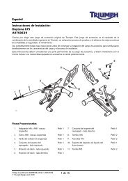
Fitting Instructions:<strong>Rocket</strong> III <strong>Touring</strong><strong>Aux</strong>iliary <strong>Lamp</strong>s, 4.5” (US Market) A9938085<strong>Fog</strong> <strong>Lamp</strong>s, 4.5” (EC Market) A9938095Thank you for choosing this Triumph genuine accessory kit. This accessory kit is the product of Triumph's useof proven engineering, exhaustive testing, and continuous striving for superior reliability, safety andperformance.Completely read all of these instructions before commencing the installation of the accessory kit in order tobecome thoroughly familiar with the kit’s features and the installation process.These instructions should be considered a permanent part of your accessory kit, and should remain with iteven if your accessory equipped motorcycle is subsequently sold.WarningThis accessory kit is designed for use on Triumph <strong>Rocket</strong> III <strong>Touring</strong> motorcycles only and should not be fitted to anyother Triumph model or to any other manufacturers motorcycle. Fitting this accessory kit to any other Triumph model, orto any other manufacturers motorcycle, may interfere with the rider and could affect the handling, stability or otheraspects of the motorcycles operation which may result in loss of motorcycle control and an accident.Parts Supplied:1. <strong>Lamp</strong> unit. . . . . . . . . . . . . . . . . . . . . . . . . . . . . 2 off 9. Screw, M8 x 25 . . . . . . . . . . . . . . . . . . . . . . . 2 off2. Mounting bar. . . . . . . . . . . . . . . . . . . . . . . . . . 1 off 10. Spacer, M8 . . . . . . . . . . . . . . . . . . . . . . . . . . . 2 off3. Indicator mounting spacer, LH . . . . . . . . . . . . 1 off 11. Bolt, M8 x 35 . . . . . . . . . . . . . . . . . . . . . . . . . 3 off4. Indicator mounting spacer, RH . . . . . . . . . . . . 1 off 12. Nut, M8 . . . . . . . . . . . . . . . . . . . . . . . . . . . . . 2 off5. Horn mounting spacer . . . . . . . . . . . . . . . . . . 1 off 13. Bolt, M6 x 20 . . . . . . . . . . . . . . . . . . . . . . . . . 3 off6. <strong>Lamp</strong> mounting bracket . . . . . . . . . . . . . . . . . 2 off 14. Cable tie . . . . . . . . . . . . . . . . . . . . . . . . . . . . . 5 off7. <strong>Lamp</strong> wiring harness . . . . . . . . . . . . . . . . . . . . 2 off 15. Relay . . . . . . . . . . . . . . . . . . . . . . . . . . . . . . . . 1 off8. Main wiring harness . . . . . . . . . . . . . . . . . . . . 1 offPublication part number <strong>A9900329</strong> issue 2, ADC 8220© Triumph Designs Ltd 20071 of 10
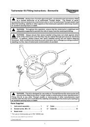
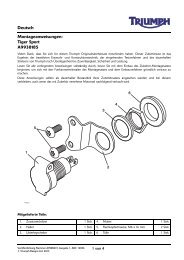
WarningAlways have Triumph approved parts, accessories and conversions fitted by a trained technician of an authorisedTriumph dealer. The fitment of parts, accessories and conversions by a technician who is not of an authorised Triumphdealer may affect the handling, stability or other aspects of the motorcycles operation which may result in loss ofmotorcycle control and an accident.WarningThroughout this operation, ensure that the motorcycle is stabilised and adequately supported to prevent risk of injuryfrom the motorcycle falling.WarningA torque wrench of known accurate calibration must be used when fitting this accessory kit. Failure to tighten any of thefasteners to the correct torque specification may result in loss of motorcycle control and an accident.1. Remove the seat as described in the service manual.2. Disconnect the battery, negative (black) lead first.3. Remove the windshield as described in the servicemanual.4. Remove the airbox cover. Remove the fuel tank frontfixings. Raise the front of the fuel tank and support inthe raised position with the prop stand as describedin the service manual.Note:• If an accessory alarm is fitted it will benecessary to remove the additional securitylocknut fitted to the right hand headstockcover top fixing. Retain the locknut for reuse.5. Remove the right hand headstock cover as describedin the service manual.6. Remove the headlamp bezel fixings. Retain thefixings for reuse.7. Remove the headlamp lens assembly from theheadlamp bowl and disconnect the headlamp andposition lamp connections.1. Headlamp lens2. Headlamp bowl3. Headlamp connection4. Position lamp connection1. Headlamp bezel2. Fixing2 of 10
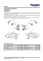
8. Locate the indicator harnesses in the headlamp bowland disconnect from the motorcycle wiring harness.Note the RH indicator wiring is identified by asection of red tape. Record this to aid reassembly.11. Remove the three M6 bolts securing the indicatorbracket to the lower yoke. Retain the fixings if themotorcycle is to be returned to its original condition.1. Indicator harnesses2. Red tape, right hand indicator9. Release any straps which may be retaining theindicator wiring harnesses to the headlamp bowl.1. Indicator bracket2. Bolt, M612. While holding the bracket, carefully feed theindicator wiring harnesses through the headlampbowl.13. Remove the indicator bracket, complete withindicator assemblies and wiring.14. Remove the indicator cable retaining clips from theindicator bracket. Retain the indicator bracket, clipsand all fixings if the motorcycle is to be returned toits original condition.1. Indicator harness2. Retaining strap10. Disconnect the horn connection and remove thehorn from the lower yoke. Retain the fixing bolt ifthe motorcycle is to be returned to its originalcondition.1. Indicator cable2. Retaining clip3. Fixing15. Remove the indicator fixings and remove theindicators from the bracket. Retain the indicatorbracket and all fixings if the motorcycle is to bereturned to its original condition.3 of 10
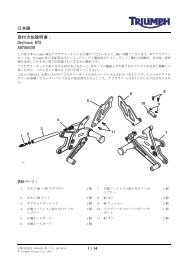
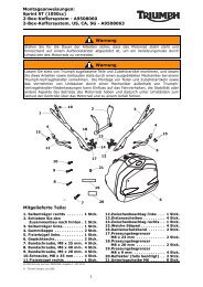
16. Feed one of the new lamp wiring harnesses throughthe slot in the new mounting bar until it emergesfrom the left hand end of the mounting bar.WarningEnsure the wiring harness does not become trappedwhen fitting the indicator assemblies to the mountingbar. A trapped harness could result in damage to thewiring which could lead to a motorcycle electrical failureresulting in loss of motorcycle control and an accident.22. Position the left hand indicator mounting spacer ontothe left hand indicator as shown.1. <strong>Lamp</strong> harness2. Slot, mounting bar17. Feed the second lamp harness through the slot, inthe opposite direction, until it emerges from the righthand side of the mounting bar.18. Carefully feed the right hand indicator harness,identified with the section of red tape, through theright hand end of the new lamp mounting bar.1. Indicator, left hand2. Mounting spacer, left hand23. Adjust the harness length to allow the indicator to bepositioned correctly on the mounting bar.24. Fit the lamp mounting bracket, as shown. Secure thebracket and left hand indicator to the mounting barwith a M8 x 25 screw.1. Indicator harness, RH2. Mounting bar, right hand side19. Retrieve the harness through the centre slot in themounting bar.20. Carefully feed the left hand indicator harnessthrough the left hand end of the new lampmounting bar.21. Retrieve the harness through the centre slot in themounting bar.1. <strong>Lamp</strong> mounting bracket2. Indicator, left hand3. Screw, M8 x 254 of 10
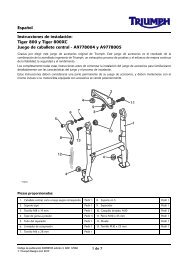
25. Position the left hand indicator and bracket at 90° tothe mounting bar. A suitable bar can be passedthrough the bracket in order to hold it in positionwhile tightening the M8 x 25 screw. Tighten thescrew to 18 Nm.26. Repeat steps 22 - 25 for the right hand indicator.27. With both indicator assemblies positioned correctlyon the mounting bar, carefully remove the indicatorlenses. Locate a flat bladed screwdriver in the lensdrain slot and turn the blade through 90° to releasethe lens from the indicator body.28. Rotate the lens through 90° and refit to position thedrain slot at the bottom.30. Remove the grommet from the lamp bowl.1. <strong>Lamp</strong> bowl2. Grommet31. Feed the left hand lamp harness, at the mountingbar end location, through the grommet.1. Indicator lens2. Drain slot29. Remove the bezel and lens assembly from one ofthe lamp units, as shown below.1. <strong>Lamp</strong> harness2. Grommet32. Feed the lamp harness into the lamp bowl and refitthe grommet.5 of 10
33. Position the lamp bowl onto the mounting bar lampbracket and secure with the M8 x 35 screw, spacerand nut as shown below. Do not fully tighten thefixings at this stage.37. Locate the new mounting bar assembly in positionon the lower yoke and secure with two of the newM6 x 20 screws at the front right hand and rear lefthand mounting points.1. <strong>Lamp</strong> bowl2. <strong>Lamp</strong> bracket3. Screw, M8 x 354. Spacer5. Nut34. For kit A9938085: Connect the white lead on thelamp harness to the white lead on the lens assembly,black lead on the harness to black lead on the lensassembly.For kit A9938095: Connect the white lead on thelamp harness to the white lead on the lens assembly,black lead on the harness to black lead on the insideof the lamp bowl.1. Mounting bar2. Screw, front right hand3. Screw, rear left hand38. Fit the remaining M6 fixing at the rear right handmounting point ensuring it also retains the brakehose clip.1. Lens assembly (A9938095 shown)2. <strong>Lamp</strong> bowl (A9938095 shown)3. White lead4. Black lead35. Refit the lamp lens assembly and secure with thefixing screw.36. Repeat steps 28 - 34 for the right hand lampassembly.1. Mounting bar2. Screw, rear right hand3. Brake hose clip39. Tighten the mounting bar fixings to 9 Nm.40. Feed the indicator harnesses following the routingnoted on removal, through the cable guide and intothe headlamp bowl.6 of 10
41. Connect the indicator harnesses to the main wiringharness, note the right hand indicator harnesses areidentified with a section of red tape.43. Refit the headlamp lens assembly to the headlampbowl. Secure with the original fixings.1. Indicator harnesses2. Red tape, right hand indicator42. Reconnect the headlamp and position lampconnections.1. Headlamp lens assembly2. Fixing44. Align the auxiliary/fog lamps on the mounting barwith the headlamp assembly and tighten the fixingsto 27 Nm.45. Feed the auxiliary/fog lamp harnesses over thebottom yoke and through the right hand side of theframe as shown.1. Headlamp connection2. Position lamp connection46. Locate the 3 pin accessory lamp connector on themain wiring harness, underneath the fuel tank.7 of 10
47. Connect the sub-harness to the 3 pin connector onthe main motorcycle wiring harness.51. Fit the horn spacer provided onto the horn mountingbracket in the position shown.1. Sub-harness2. Motorcycle main harness48. Locate the accessory relay mounting bracketunderneath the fuel tank. Fit the sub harness relayconnector to the relay bracket in one of the twomounting positions.1. Horn mounting bracket2. Spacer52. Refit the horn to the motorcycle and secure with anew M8 x 35 screw. Tighten the screw to 27 Nm.1. Relay connector, sub harness2. Accessory relay mounting bracket49. Fit the relay provided into the sub harness relayconnector.50. Ensure all wiring is correctly routed and does not foulor obstruct any existing component. Secure inposition with the cable ties provided.1. Horn2. Horn mounting bracket3. Spacer4. M8 x 35 screw53. Reconnect the horn wiring.8 of 10
WarningAfter fitting the accessory kit the motorcycle will exhibit new handling characteristics. Operate the motorcycle in a safearea free from traffic to gain familiarity with any new characteristics. Operation of the motorcycle when not familiar withany new handling characteristics may result in loss of motorcycle control and an accident.WarningIf, after fitment of this accessory kit, you have any doubt about the performance of any aspect of the motorcycle, contactan authorised Triumph dealer and do not ride the motorcycle until the authorised dealer has declared it fit for use.Riding a motorcycle when there is any doubt as to any aspect of the performance of the motorcycle may result in loss ofcontrol of the motorcycle leading to an accident.WarningNever ride an accessory equipped motorcycle at speeds above 80 mph (130 km/h).The presence of accessories will cause changes in the stability and handling of the motorcycle. Failure to allow forchanges in motorcycle stability may lead to loss of control or an accident.Remember that the 80 mph (130 km/h) limit will be reduced by the fitting of non-approved accessories, incorrectloading, worn tyres, overall motorcycle condition and poor road or weather conditions.WarningThe motorcycle must not be operated above the legal road speed limit except in closed course conditions.WarningOnly operate this Triumph motorcycle at high speed in closed-course on road competition or on closed courseracetracks. High speed operation should only be attempted by riders who have been instructed in the techniquesnecessary for high speed riding and are familiar with the motorcycle’s characteristics in all conditions.High speed operation in any other circumstances is dangerous and will lead to loss of motorcycle control and anaccident.10 of 10