Specification Bulletin 682-31 - S&C Electric Company
Specification Bulletin 682-31 - S&C Electric Company
Specification Bulletin 682-31 - S&C Electric Company

You also want an ePaper? Increase the reach of your titles
YUMPU automatically turns print PDFs into web optimized ePapers that Google loves.
S&C Remote Supervisory Vista® Underground Distribution SwitchgearOutdoor Distribution (15.5 kV through 38 kV)<strong>Specification</strong>sConditions of SaleSTANDARD: Seller’s standard conditions of sale set forthin Price Sheet 150 apply.SPECIAL TO THIS PRODUCT:INCLUSIONS: S&C Remote Supervisory Vista UndergroundDistribution Switchgear (UDS) provides automatedswitching and fault protection for underground distributionsystems. It is available in three styles: UnderCover, Vault-Mounted, and Pad-Mounted. Each style is available withup to six “ways”—bus terminals, switches, and/or faultinterrupters in ratings through 38 kV, and 25 kA symmetrical.Remote Supervisory Vista UDS features load-interrupterswitches for switching 600- or 900-ampere main feeders,and microprocessor-controlled, resettable, vacuumfault interrupters for switching and protection of 600- or900-ampere main feeders and 200-, 600-, or 900-ampere taps,laterals, and subloops. These elbow-connected componentsare enclosed in a submersible, SF 6 -insulated, welded-steeltank, completely protected from the environment.Since Remote Supervisory Vista UDS is submersibleand considerably smaller than traditional air-insulatedgear, it can be installed exactly where needed . . . evensubsurface. Aesthetics of the installation are improved andcost is lowered through reduced trenching and cable runs.Switchgear installed subsurface can be readily operatedfrom grade level.The three-position (“closed”-“open”-“grounded”)load-interrupter switches may be manually operated ormotor operated and provide three-pole live switching of600-ampere three-phase circuits. A visible gap is providedwithout exposure to medium voltage or need to manipulateelbows.The 200-, 600-, and 900-ampere fault interruptersfeature resettable vacuum interrupters in series withmanually operated three-position (“closed”-“open”-“grounded”) disconnects for isolation and internalgrounding of each phase. Fault interrupters providethree-pole load switching and fault interruption through25 kA symmetrical, or single-pole load switching and faultinterruption through 12.5 kA symmetrical (for other possibleratings, refer to the nearest S&C Sales Office). Three-polefault interrupters may be fitted with motor operators.A manual handle is provided for operating load-interrupterswitches and fault interrupters. The operating mechanismsfunction independently of the speed of the manual handleand are designed to prevent inadvertent operation fromthe “closed” position directly to the “grounded” positionand vice versa. Operating shafts are padlockable in anyposition and can also be padlocked to prevent operationto the “grounded” position.Large windows provide a clear view of the open gap,ground position, and ground bus . . . allowing the operator toeasily confirm the positions of the load-interrupter switchesand disconnects of the fault interrupters. Trip indicatorsfor the fault interrupters are readily visible through thewindows as well.Terminals are equipped with 200-ampere bushing wellsor 600- or 900-ampere bushings, as specified. Bushing andbushing-well interfaces conform with IEEE Standard 386and accept all standard insulated connectors and inserts.In addition, Vista UDS has been certified as arc resistantper IEC 298 Appendix AA for fault currents up to 12.5 kAsymmetrical for 15 cycles. Arc resistance is standardfor the Pad-Mounted and UnderCover Styles. For theVault-Mounted Style, Catalog Number Suffix “-N” mustbe specified, in which case a flange will be welded to thepressure relief device for connection of user-supplied pipingto vent exhaust gases out of the vault area.Overcurrent ControlFault interruption is initiated by a programmable overcurrentcontrol housed in a watertight enclosure. The controlis programmed using a personal computer connectedthrough an adapter cable, listed in the table of accessorieson page 15. Total clearing time (from initiation of faultto clearing) is as little as 40 milliseconds. For single-polefault interrupters, the overcurrent control can also beprogrammed to provide three-pole fault interruption.Power and input signals for the overcurrent control areprovided by current transformers. The control features avariety of time-current characteristic curves—standard “E”speed curves, “K” speed curves, innovative “coordinating”speed tap and main curves, and relay curves per IEEEC37.112-1996.Coordinating-speed tap curves are used for faultinterrupters feeding subloop taps and are specificallydesigned to optimize coordination with load-side weak-link/backup current-limiting fuse combinations and source-siderelays with low time-dial settings. Coordinating-speed maincurves are used for fault interrupters on main feeders andhave a longer minimum-response time and different shapeto coordinate with tap-interrupter curves.September 7, 2010© S&C <strong>Electric</strong> <strong>Company</strong> <strong>Specification</strong> <strong>Bulletin</strong> <strong>682</strong>-<strong>31</strong>
S&C Remote Supervisory Vista® Underground Distribution SwitchgearConditions of Sale—ContinuedCoordinating-speed curves have phase-overcurrentand—for three-pole tripping fault interrupters only—ground-overcurrent settings. (The latter can be turned offif desired.) These curves can be tailored to the applicationusing a variety of instantaneous and definite-time settings.UnderCover StyleWhen the UnderCover Style is specified, a stainless-steeltank with submersible wiring is furnished suitable forunderground installation. A mild-steel or, optionally,stainless-steel low-voltage enclosure is mounted on acustomer-supplied pad at grade level. It is connected to thetank with cabling up to 45 feet in length.Vault-Mounted StyleTwo versions of this style are available: Wet-Vault-MountedStyle is intended for vaults that are subject to periodicflooding and includes submersible wiring and electricalcomponents. Dry-Vault-Mounted Style is intended for vaultsthat are not subject to periodic flooding and does not includesubmersible wiring and electrical components.When the Wet-Vault-Mounted Style is specified, astainless-steel tank is furnished, suitable for mounting on thefloor or wall of a vault. When the Dry-Vault-Mounted Style isspecified, a mild-steel tank is furnished. The mild-steel or,optionally, stainless-steel low-voltage enclosure is mountedon the vault floor or wall; it is connected to the tank withcabling up to 45 feet in length.Pad-Mounted StyleWhen the Pad-Mounted Style is specified, a mild-steel or,optionally, stainless-steel enclosure is furnished. A mild-steelor, optionally, stainless-steel low-voltage compartment ismounted on the side of the enclosure.Although the Vista UDS tank itself is submersible, manyof the electrical components mounted to the tank are not.Special submersible components and wiring are providedwhen the UnderCover Style or Wet-Vault-Mounted Styleis specified. Contact your nearest S&C Sales Office forinformation on Pad-Mounted Style units with submersiblewiring.Pad-mounted enclosures meet the requirements ofANSI Standard C57.12.28 for enclosure integrity. The topof the enclosure is hinged on both sides for convenientaccess to the operating and termination compartments.A removable panel provides access to the elbows andcables and is secured by the overlapping padlockable top.A resilient closed-cell gasket on the enclosure bottomflange protects the finish from being scratched duringinstallation and isolates it from the alkalinity of a concretefoundation. Enclosures are protected from corrosion byS&C’s Ultradur® Finishing System.Motor Operators and SensingMotor operators provide the basis for automation. Therobust Vista motor operator is available factory-installed orit can be readily installed in the field. It is easily removedfor testing of the communication and control equipmentwithout actually operating the gear.Three-phase voltage sensing and three-phase currentsensing are available for motor operated ways.Low-Voltage Compartment EnclosureMotor operator controls are located within the low-voltagecompartment. Each motor operator is provided witha control board which includes “Close,” “Open,” and,optionally, “Ground” push buttons; switch-positionindicating lamps; operation counter; lamp test button;and receptacle for portable remote control station. Up tosix control boards can be accommodated, so any or allload-interrupter switches or three-pole fault interrupterways may be motor operated. A single “Local/Remote”switch is provided for all control boards, permitting anon-site operator to take complete control of the gear.A 36-volt, 5-ampere-hour, rechargeable, sealed-starvedelectrolytelead battery pack and 80-watt temperaturecompensatedoutput battery charger are also furnished inthe low-voltage compartment. The battery charger featuresintegral load-disconnect circuitry to prevent deep-dischargeof batteries on loss of ac source; alarms for loss of ac source,battery low voltage, and charger overvoltage; and a remoteor locally initiated battery test function. It provides both36-Vdc and 12-Vdc outputs. The battery charger requiresa 120-Vac, 50/60-Hz or 240-Vac, 50/60-Hz external powersupply; internal control power is optionally available.Connections are provided for the external power input;“close,” “open,” and, optionally, “ground” command inputs;switch-position indication; current- and voltage-sensoroutputs; and battery-test and battery-status outputs.Communication and Control EquipmentA user-specified remote terminal unit (RTU) and communicationdevice may be furnished in the low-voltagecompartment, providing a completely automated distributionswitching and protection package. Contact yournearest S&C Sales Office for details. Alternately, a controlunit for use with RTU by others or a control unit for usewithout RTU may be furnished. One of these three controlequipment packages must be specified when ordering. Seethe table on page 11.2 S&C <strong>Specification</strong> <strong>Bulletin</strong> <strong>682</strong>-<strong>31</strong>
S&C Remote Supervisory Vista® Underground Distribution SwitchgearPotential Indication with Test FeatureWhen this optional voltage indication is specified, allroutine operating tasks—switching, voltage testing, andgrounding—can be accomplished by a single person withoutcable handling or exposure to medium voltage. This featureis available with or without provisions for low-voltagephasing. Cable testing for faults can be performed throughthe back of a user-supplied elbow or through a user-suppliedfeedthru insert, eliminating the need for cable handling oruse of parking stands.EXCLUSIONS: The purchaser must specify the switchgearstyle, communication and control equipment, motoroperator package, and any desired optional features tocomplete the catalog number of the switchgear.Communication devices, when specified, do not includeantenna, antenna support, surge protection, or coaxialfeedline. Propagation study, frequency selection, and FCClicense application are also to be provided by others.WARRANTY QUALIFICATIONS: The standard warrantycontained in seller’s standard conditions of sale (as set forthin Price Sheet 150) does not apply to major componentsnot of S&C manufacture, such as remote terminal unitsand communication devices, including hardware, software,resolution of protocol-related matters, and notification ofupgrades or fixes for those devices.Seller’s standard warranty does not apply to anycomponents not of S&C manufacture that are suppliedand installed by the purchaser, nor to the ability of seller’sequipment to work with such components.APPLICATION NOTES: Fault Interrupter—Completeratings for the fault interrupter are shown in the table onpage 4. In addition to the load-dropping ratings shown,the fault interrupter is capable of interrupting transformermagnetizing currents associated with the applicable loads,as well as line-charging and cable-charging currents typicalfor distribution systems of these voltage ratings.The duty-cycle fault-closing rating and ten-timeduty-cycle fault-interrupting rating shown for the faultinterrupter define, respectively, the level of availablethree-phase fault current into which the fault interrupter canbe closed the designated number of times in the “closed” or“grounded” position and subsequently interrupt, with thefault interrupter remaining operable and able to interruptrated continuous current.A Note on Single-Pole SwitchingIn single-pole switching of ungrounded-primary three-phasetransformers or banks (or single-phase transformersconnected line-to-line), circuit connections or parametersmay, in some cases, produce excessive overvoltages. Inparticular, for the following applications above 22 kV,single-pole switching should be performed only under theconditions stated in italics:• Switching unloaded or lightly loaded delta-connectedor ungrounded-primary wye-wye connected three-phasetransformers or banks (or line-to-line connected singlephasetransformers), rated 150 kVA or less three-phase,or 50 kVA or less single-phase—or of any kVA rating whencombined with unloaded cables or lines—where maximumsystem operating voltage exceeds 22 kV. Singlepoleswitching should be performed only if each phaseis carrying 5% load or more, or if the transformer orbank is temporarily grounded at the primary neutralduring switching.• Switching loaded or unloaded ungrounded-primary wyedeltaconnected three-phase transformers or banks—alone or combined with unloaded cables or lines—wheremaximum system operating voltage exceeds 22 kV.Single-pole switching should be performed only if eachphase is carrying 5% load or more and if the lightingloadphase is always switched open first (or switchedclosed last); or if the transformer or bank is temporarilygrounded at the primary neutral during switching.Load-Interrupter Switch—Complete ratings for theload-interrupter switch are shown in the table onpage 4. In addition to the load-dropping ratings shown,the load-interrupter switch is capable of interruptingtransformer magnetizing currents associated with theapplicable loads, as well as line-charging and cable-chargingcurrents typical for distribution systems of these voltageratings. For applications involving load current with highharmonic content (such as rectifier load currents), refer tothe nearest S&C Sales Office.The duty-cycle fault-closing rating shown for theload-interrupter switch defines the level of availablethree-phase fault current into which the load-interrupterswitch can be closed the designated number of times in the“closed” or “grounded” position, with the load-interrupterswitch remaining operable and able to interrupt ratedcontinuous current.S&C <strong>Specification</strong> <strong>Bulletin</strong> <strong>682</strong>-<strong>31</strong> 3
S&C Remote Supervisory Vista® Underground Distribution SwitchgearThe following items should be considered when applyingRemote Supervisory Vista UDS:Ungrounded systems. The S&C voltage sensors areconnected phase-to-ground, and are therefore not intendedfor use on ungrounded systems. Contact your nearestS&C Sales Office for information on applying RemoteSupervisory Vista UDS on ungrounded systems.Uni-Grounded and Resistance-Grounded Systems.Uni-grounded and resistance-grounded systems requirepower to be provided by a phase-to-phase connectedvoltage transformer. When the self-powered option (-Y4)is specified, the internal voltage transformer is connectedphase-to-ground. Therefore, power must be supplied by anexternal source if Remote Supervisory Vista UDS is to beapplied on a resistively grounded or uni-grounded system.Contact your nearest S&C Sales Office for information onapplying Remote Supervisory Vista UDS on ungroundedsystems.50/60-Hz ANSI RATINGS—IEC Ratings in Parentheses12kVAmperes, RMSFault InterrupterLoad-Interrupter SwitchSystemClassMaxBILMain BusCont.CurrentShort-Circuit,Sym.Cont., LoadDropping,and LoadSplitting3Ten-Time Duty-CycleFault-Closing, Sym.IntoClosedPositionIntoGroundedPositionTen-TimeDuty-CycleFault-Interr.,Sym.Cont., LoadDropping,and LoadSplitting3Ten-TimeDuty-CycleFault-Closing,Sym.4Mom. andOne-Second,Sym.15.5(12)15.5(15.5)95(95)600(630)f12 500(12 500)25 000(25 000)200(200)d600(630)l12 500(12 500)25 000(25 000)12 500(12 500)h12 500(12 500)25 000(25 000)600(630)a600(630)k16 000(16 000)h12 500(12 500)25 000(25 000)27(24)29(29)125(125)600(630)f12 500(12 500)25 000(25 000)200(200)d600(630)l12 500(12 500)25 000(25 000)12 500(12 500)h12 500(12 500)25 000(25 000)600(630)a600(630)k16 000(16 000)h12 500(12 500)25 000(25 000)38(36)38(38)150(150)600(630)f12 500(12 500)25 000(25 000)200(200)d600(630)l12 500(12 500)25 000(25 000)12 500(12 500)h12 500(12 500)25 000(25 000)600(630)a600(630)k16 000(16 000)h12 500(12 500)25 000(25 000)1 ANSI ratings have been assigned in accordance with the applicableportions of IEEE C37.71, C37.72, and C37.73. IEC Ratings have beenassigned in accordance with the applicable portions of IEC 265-1 for aClass A switch.2 Refer to the nearest S&C Sales Office for other possible ratings.3 Parallel or loop switching. Fault interrupters and load-interrupterswitches can switch the magnetizing current of transformers associatedwith the load-dropping rating. Unloaded cable switching rating:10 amperes at 15.5 kV, 20 amperes at 29 kV and 38 kV.4 Applicable to fault closing into closed or grounded position.f 1200 (1200) amperes when switchgear is furnished with optionalcopper bus, Catalog Number Suffix “-Z5.”d 600 (630) amperes when switchgear is furnished with optional600-ampere bushings at fault interrupter terminals, Catalog NumberSuffix “-M2” or “-M3.”l 900 (900) amperes when switchgear is furnished with optional900-ampere fault interrupters, Catalog Number Suffix “-Q1” through“-Q6,” plus optional copper bus, Catalog Number Suffix “-Z5.”h 25,000 (25,000) amperes symmetrical three-time duty-cycle faultclosingrating; 16,000 (16,000) amperes symmetrical ten-time duty-cyclefault-closing rating.a 200 (200) amperes when switchgear is furnished with optional200-ampere bushing wells at load-interrupter switch terminals, CatalogNumber Suffix “-M4.”k 900 (900) amperes when switchgear is furnished with optional900-ampere load-interrupter switches, Catalog Number Suffix“-K1” through “-K6,” plus optional copper bus, Catalog NumberSuffix “-Z5.”How to Order1. Complete the worksheet on page 5 to determine the completecatalog number of the desired unit of Remote SupervisoryVista Underground Distribution Switchgear.2. Obtain the catalog number of desired accessories,USB cable kit, and touch-up kit from the tables onpage 15.4 S&C <strong>Specification</strong> <strong>Bulletin</strong> <strong>682</strong>-<strong>31</strong>
S&C Remote Supervisory Vista® Underground Distribution SwitchgearWorksheetModel Number and Base Catalog Number. Select the appropriate model number and thebase catalog number from the table on pages 7, 8, and 9.Model Number:Base Catalog Number:Switchgear Style Suffix. Select the appropriate switchgear style suffix from the table onpage 10.Fault Interrupter Suffix (applicable to 12.5-kA-rated models only). Select the appropriatefault interrupter suffix from the table on page 11.Communication and Control Equipment Suffix. Select the appropriate communicationand control equipment suffix from the table on page 11.Switchgear Style Suffix:Fault Interrupter Suffix:Communication andControl Equipment Suffix:---Internal Control Power Suffix. If internal control power is desired, specify Suffix “-Y4.”See the table on page 11.Internal Control PowerSuffix:-Optional Feature Suffix(es). Select the suffix(es) of desired optional features from thetable on pages 13 and 14.Option Suffix 1: Suffix 2: Suffix 3: Suffix 4: Suffix 5: Suffix 6:- - - - - -Motor Operator Suffix. Using this table, “X” the load-interrupter switch ways and/or three-phase fault interrupter ways to befurnished with motor operators. To determine the motor operator suffix, write the selected way numbers after “-A.”See the table on page 12.Motor Operated Suffix:Motor-Operated Way 1 2 3 4 5 6 - ACurrent Sensing Suffix. Using this table, “X” the motor-operated ways to be furnished with three-phase current sensors. Todetermine the current sensing suffix, write the selected way numbers after “-B.” See the table on page 12.Current Sensing Suffix:Current-Sensor-Equipped Way 1 2 3 4 5 6 - BVoltage Sensing Suffix. Using this table, “X” the motor-operated ways to be furnished with three-phase voltage sensors. Todetermine the voltage sensing suffix, write the selected way numbers after “-D.” See the table on page 12.Voltage Sensing Suffix:Voltage-Sensor-Equipped Way 1 2 3 4 5 6 - DComplete Catalog Number, Including Suffixes:S&C <strong>Specification</strong> <strong>Bulletin</strong> <strong>682</strong>-<strong>31</strong> 5
S&C Remote Supervisory Vista® Underground Distribution SwitchgearWorksheetModel Number and Base Catalog Number. Select the appropriate model number and thebase catalog number from the table on pages 7, 8, and 9.Switchgear Style Suffix. Select the appropriate switchgear style suffix from the table onpage 10.Fault Interrupter Suffix (applicable to 12.5-kA-rated models only). Select the appropriatefault interrupter suffix from the table on page 11.Communication and Control Equipment Suffix. Select the appropriate communicationand control equipment suffix from the table on page 11.Internal Control Power Suffix. If internal control power is desired, specify Suffix “-Y4.” Seethe table on page 11.Model Number:422Base Catalog Number:944222Switchgear Style Suffix:- P4Fault Interrupter Suffix:- T1Communication andControl Equipment Suffix:- Y6Internal Control PowerSuffix:- Y4Optional Feature Suffix(es). Select the suffix(es) of desired optional features from thetable on pages 13 and 14.Option Suffix 1: Suffix 2: Suffix 3: Suffix 4: Suffix 5: Suffix 6:- L2 - - - - -Motor Operator Suffix. Using this table, “X” the load-interrupter switch ways and/or three-phase fault interrupter ways to befurnished with motor operators. To determine the motor operator suffix, write the selected way numbers after “-A.”See the table on page 12.Motor Operated Suffix:Motor-Operated Way 1 2 3 4 5 6 - A13Current Sensing Suffix. Using this table, “X” the motor-operated ways to be furnished with three-phase current sensors. Todetermine the current sensing suffix, write the selected way numbers after “-B.” See the table on page 12.Current Sensing Suffix:Current-Sensor-Equipped Way 1 2 3 4 5 6 - B13Voltage Sensing Suffix. Using this table, “X” the motor-operated ways to be furnished with three-phase voltage sensors. Todetermine the voltage sensing suffix, write the selected way numbers after “-D.” See the table on page 12.Voltage Sensing Suffix:Voltage-Sensor-Equipped Way 1 2 3 4 5 6 - D13Complete Catalog Number, Including Suffixes:944222-P4T1Y6Y4L2A13B13D136 S&C <strong>Specification</strong> <strong>Bulletin</strong> <strong>682</strong>-<strong>31</strong>
S&C Remote Supervisory Vista® Underground Distribution SwitchgearTHREE-PHASE UNITSRatings3Model1One-Line Diagram2MaxkVBILShort-CircuitAmperes,RMS, Sym.CatalogNumberNet Weight,Lbs. (Kg)415.5 9512 50025 000942012862012550 (247.5)550 (247.5)20129 12512 50025 000942013862013550 (247.5)550 (247.5)38 15012 50025 000942014d862014d800 (360)800 (360)15.5 9512 50025 000942102862102d550 (247.5)550 (247.5)21029 12512 50025 000942103862103d550 (247.5)550 (247.5)38 15012 50025 000942104d862104d800 (360)800 (360)15.5 9512 50025 000942112862112d550 (247.5)550 (247.5)21129 12512 50025 000942113862113d550 (247.5)550 (247.5)38 15012 50025 000942114d862114d800 (360)800 (360)15.5 9512 50025 000943202863202825 (371.25)825 (371.25)32029 12512 50025 000943203863203825 (371.25)825 (371.25)38 15012 50025 0009432048632041075 (483.75)1075 (483.75)15.5 9512 50025 000943212863212825 (371.25)825 (371.25)32129 12512 50025 000943213863213825 (371.25)825 (371.25)38 15012 50025 0009432148632141075 (483.75)1075 (483.75)15.5 9512 50025 000943302863302825 (371.25)825 (371.25)33029 12512 50025 000943303863303825 (371.25)825 (371.25)38 15012 50025 0009433048633041075 (483.75)1075 (483.75)1 The model number defines the total number of ways, the number ofload-interrupter switch ways, and the number of fault-interrupter ways.For example, a Model 4<strong>31</strong> has “4” ways in total of which “3” are loadinterrupterswitch ways and “1” is a fault-interrupter way.2 Refer to your nearest S&C Sales Office for other possibleconfigurations.3 Refer to the ratings table on page 4 for continuous, load-dropping,interrupting, and momentary ratings. For complete live-switching ratingsfor load-interrupter switches and fault interrupters as applied in S&CVista Underground Distribution Switchgear, refer to “Application Notes”on page 3.4 Welded-steel tank including components and SF 6 gas.d These models have not been certified as arc resistant for unrestrictedaccess. Refer to your nearest S&C Sales Office.TABLE CONTINUED vS&C <strong>Specification</strong> <strong>Bulletin</strong> <strong>682</strong>-<strong>31</strong> 7
S&C Remote Supervisory Vista® Underground Distribution SwitchgearTHREE-PHASE UNITS—ContinuedModel14134224<strong>31</strong>440One-Line Diagram21 The model number defines the total number of ways, the number ofload-interrupter switch ways, and the number of fault-interrupter ways.For example, a Model 4<strong>31</strong> has “4” ways in total of which “3” are loadinterrupterswitch ways and “1” is a fault-interrupter way.2 Refer to your nearest S&C Sales Office for other possibleconfigurations.MaxkVRatings3BIL15.5 9529 12538 15015.5 9529 12538 15015.5 9529 12538 15015.5 9529 12538 150Short-CircuitAmperes, RMS,Sym.12 50025 00012 50025 00012 50025 00012 50025 00012 50025 00012 50025 00012 50025 00012 50025 00012 50025 00012 50025 00012 50025 00012 50025 000CatalogNumber944132864132944133864133944134864134944222864222944223864223944224864224944<strong>31</strong>2864<strong>31</strong>2944<strong>31</strong>3864<strong>31</strong>3944<strong>31</strong>4864<strong>31</strong>4944402864402944403864403944404864404Net Wt.,Lbs. (Kg)41100 (495)1100 (495)1100 (495)1100 (495)1350 (607.5)1350 (607.5)1100 (495)1100 (495)1100 (495)1100 (495)1350 (607.5)1350 (607.5)1100 (495)1100 (495)1100 (495)1100 (495)1350 (607.5)1350 (607.5)1100 (495)1100 (495)1100 (495)1100 (495)1350 (607.5)1350 (607.5)3 Refer to the ratings table on page 4 for continuous, load-dropping,interrupting, and momentary ratings. For complete live-switching ratingsfor load-interrupter switches and fault interrupters as applied in S&CVista Underground Distribution Switchgear, refer to “Application Notes”on page 3.4 Welded-steel tank including components and SF 6 gas.TABLE CONTINUED v8 S&C <strong>Specification</strong> <strong>Bulletin</strong> <strong>682</strong>-<strong>31</strong>
S&C Remote Supervisory Vista® Underground Distribution SwitchgearTHREE-PHASE UNITS—ContinuedRatings3Model1One-Line Diagram2MaxkVBILShort-CircuitAmperes, RMS,Sym.CatalogNumberNet Wt.,Lbs. (Kg)451452362463<strong>31</strong> The model number defines the total number of ways, the number ofload-interrupter switch ways, and the number of fault-interrupter ways.For example, a Model 4<strong>31</strong> has “4” ways in total of which “3” are loadinterrupterswitch ways and “1” is a fault-interrupter way.2 Refer to your nearest S&C Sales Office for other possibleconfigurations.15.5 9529 12538 15015.5 9529 12538 15015.5 9529 12538 15015.5 9529 12538 15012 50025 00012 50025 00012 50025 00012 50025 00012 50025 00012 50025 00012 50025 00012 50025 00012 50025 00012 50025 00012 50025 00012 50025 0009451428651429451438651439451448651449452328652329452338652339452348652349462428662429462438662439462448662449463328663329463338663339463348663341100 (495)1100 (495)1100 (495)1100 (495)1350 (607.5)1350 (607.5)1100 (495)1100 (495)1100 (495)1100 (495)1350 (607.5)1350 (607.5)1375 (618.75)1375 (618.75)1375 (618.75)1375 (618.75)1625 (7<strong>31</strong>.25)1625 (7<strong>31</strong>.25)1650 (742.5)1650 (742.5)1650 (742.5)1650 (742.5)1900 (855)1900 (855)3 Refer to the ratings table on page 4 for continuous, load-dropping,interrupting, and momentary ratings. For complete live-switching ratingsfor load-interrupter switches and fault interrupters as applied in S&CVista Underground Distribution Switchgear, refer to “Application Notes”on page 3.4 Welded-steel tank including components and SF 6 gas.S&C <strong>Specification</strong> <strong>Bulletin</strong> <strong>682</strong>-<strong>31</strong> 9
S&C Remote Supervisory Vista® Underground Distribution SwitchgearSWITCHGEAR STYLESItemSuffix to beAdded toSwitchgearCatalog NumberApplicableto ModelsNet Weight,Lbs. (Kg)1UnderCover Style. Includes stainless-steel tank, submersible wiring, and25-foot submersible control cable for attachment to olive-green finish mildsteellow-voltage enclosureDry-Vault-Mounted Style. Includes mild-steel tank and 25-foot control cablefor attachment to olive-green finish mild-steel low-voltage enclosure. Doesnot include submersible wiringWet-Vault-Mounted Style. Includes stainless-steel tank, submersible wiring,and 25-foot submersible control cable for attachment to olive-green finishmild-steel low-voltage enclosurePad-Mounted Style.Includes padmountedenclosurefor mountingswitchgear withintegral low-voltagecompartment ona padTwowayunitThreeorfourwayunitFive- orsix-wayunitMild-steel outerenclosure and lowvoltagecompartmentStainless-steel outerenclosure and lowvoltagecompartmentMild-steel outerenclosure and lowvoltagecompartmentStainless-steel outerenclosure and lowvoltagecompartmentMild-steel outerenclosure and lowvoltagecompartmentStainless-steel outerenclosure and lowvoltagecompartment-U201, 210, 211320, 321, 330413, 422, 4<strong>31</strong>, 440514, 523624, 633-V3 All models-V4 All modelsOlive green finish -P2 201, 210, 211Light gray finish -P7 201, 210, 211Olive green finish -P12 201, 210, 211Light gray finish -P17 201, 210, 211Olive green finish -P4 320, 321, 330, 413, 422, 4<strong>31</strong>, 440Light gray finish -P9 320, 321, 330, 413, 422, 4<strong>31</strong>, 440Olive green finish -P14 320, 321, 330, 413, 422, 4<strong>31</strong>, 440Light gray finish -P19 320, 321, 330, 413, 422, 4<strong>31</strong>, 440Olive green finish -P6 514, 523, 624, 633Light gray finish -P11 514, 523, 624, 633Olive green finish -P16 514, 523, 624, 633Light gray finish -P21 514, 523, 624, 63323534f(240.3)693f(<strong>31</strong>1.85)986f(443.7)1 When Internal Control Power, Catalog Number Suffix “-Y4,” is specified,the size and weight of the tank and outer enclosure may increase ontwo-way units rated 12.5 kA short-circuit and four-way units. An appropriatedimensional drawing will be furnished.2 Weight of low-voltage enclosure (less components) is 185 pounds(83.25 kg).3 Weight of low-voltage enclosure (less components) is 174 pounds(78.3 kg).f Weight includes outer enclosure, base spacer, and empty low-voltagecompartment.10 S&C <strong>Specification</strong> <strong>Bulletin</strong> <strong>682</strong>-<strong>31</strong>
S&C Remote Supervisory Vista® Underground Distribution Switchgearcommunication and control equipment—One Suffix Must Be SpecifiedCustom Communication and Control Package. Includes push buttons for local control of motoroperators, LED position indicators, operation counter, battery charger, and battery packs. Alsoincludes user-specified remote terminal unit (RTU) and user-specified communication device.Requires user-supplied 120-volt 50/60-Hz ac external power source for battery charger. Othervoltages are available upon requestItemSuffix to be Addedto SwitchgearCatalog NumberfApplicableto ModelsAllControl Unit for Use With RTU by Others. Includes push buttons for local control of motor operators,LED position indicators, operation counter, battery charger, and battery packs. Also includesprovisions for mounting user-supplied, user-installed RTU and communication device in low-voltageenclosure or compartment. Requires user-supplied 120-volt 50/60-Hz ac external power source forbattery charger. Other voltages are available upon requestControl Unit for Use Without RTU. Includes push buttons for local control of motor operators, LEDposition indicators, operation counter, battery charger, and battery packs. Requires user-supplied120-volt 50/60-Hz ac external power source for battery charger. Other voltages are available uponrequestf Refer to your nearest S&C Sales Office.-Y3 All-Y6 AllINTERNAL CONTROL POWER12ItemInternal Control Power. Includes push buttons for local control of motor operators, LED positionindicators, operation counter, battery charger, and battery packs. A voltage transformer is mountedinside the Vista UDS tank and supplies control power to battery charger and battery packsSuffix to be Added toBase Catalog Number-Y4Applicableto ModelsAll, through5 ways1 If internal control power is not specified, user must supply 120-Vaccontrol power to low-voltage enclosure.2 May increase the size and weight of the tank and outer enclosure ontwo-way units rated 12.5 kV short-circuit and four-way units. An appropriatedimensional drawing will be furnished.SINGLE-POLE OR THREE-POLE FAULT INTERRUPTING123ItemSuffix to be Addedto SwitchgearCatalog NumberSingle-Pole Manual Fault Interrupter on all fault-interrupting ways -T0Three-Pole Manual Fault Interrupter on one fault-interrupting way (single-pole manual faultinterrupter on all other fault-interrupting ways)Three-Pole Manual Fault Interrupter on two fault-interrupting ways (single-pole manual faultinterrupter on all other fault-interrupting ways)Three-Pole Manual Fault Interrupter on three fault-interrupting ways (single-pole manual faultinterrupter on all other fault-interrupting ways)Three-Pole Manual Fault Interrupter on four fault-interrupting ways (single-pole manual faultinterrupter on all other fault-interrupting ways)Three-Pole Manual Fault Interrupter on five fault-interrupting ways (single-pole manual faultinterrupter on all other fault-interrupting ways)Three-Pole Manual Fault Interrupter on six fault-interrupting ways -T61 Not applicable to models rated 25 kA short circuit. All 25-kA-ratedmodels include three-pole manual fault interrupters.2 Refer to the nearest S&C Sales Office for other possible configurations.-T1-T2-T3-T4-T5Applicableto Models12.5-kA-rated modelswith 1 or more faultinterrupters12.5-kA-rated modelswith 1 or more faultinterrupters12.5-kA-rated modelswith 2 or more faultinterrupters12.5-kA-rated modelswith 3 or more faultinterrupters12.5-kA-rated modelswith 4 or more faultinterrupters12.5-kA-rated modelswith 5 or more faultinterrupters12.5-kA-rated modelswith 6 or more faultinterrupters3 For standard models, components are in the following order (from leftto right) when facing the operating side of the gear: load switches, bustaps, three-pole fault interrupters, single-pole fault interrupters.S&C <strong>Specification</strong> <strong>Bulletin</strong> <strong>682</strong>-<strong>31</strong> 11
S&C Remote Supervisory Vista® Underground Distribution Switchgearmotor operator options—Option Suffix “-A”ItemMotor Operator Package. Includes motor operator for use on load-interrupter switch way or three-pole faultinterrupterway; motor-operator control board with “CLOSE,” “OPEN,” and, optionally, “GROUND” push buttons;push-to-test indicator lamps; operation counter; and adapter for portable remote-control station. Thereis only one “LOCAL/REMOTE” switch for the entire gear. Also includes connections for the user-supplied externalcontrol power; “close,” “open,” and, optionally, “ground” command inputs; and switch-position indicationTotal Number of Motor-OperatedWays on the Gear121234561 Refer to the “How to Order” section on pages 4 through 6 to computethe total number of motor-operated ways and generate the proper optionsuffix for the motor operator option.2 Each motor operator weighs 24.5 pounds (11.03 kg).sensing options for motor-operated waysThree-Phase Current Sensing—Option Suffix “-B”12Includes three current sensors for each way selectedItemThree-Phase Voltage Sensing—Option Suffix “-D”34Includes three-phase line-to-ground voltage sensing for each way selected1 Refer to the “How to Order” section on pages 4 through 6 to computethe total number of motor-operated ways with current sensing and generatethe proper option suffix for current sensing.2 Current sensor ratio is 600:5.Total Number of Motor-OperatedWays on the Gear3 Refer to the “How to Order” section on pages 4 through 6 to computethe total number of motor-operated ways with voltage sensing and generatethe proper option suffix for voltage sensing.4 Refer to the nearest S&C Sales Office for specifications on the voltagesensing circuit.12345612345612 S&C <strong>Specification</strong> <strong>Bulletin</strong> <strong>682</strong>-<strong>31</strong>
S&C Remote Supervisory Vista® Underground Distribution SwitchgearOPTIONAL FEATURESItemSuffix to beAdded toSwitchgearCatalog NumberApplicable to ModelsStainless-Steel Tank for Dry-Vault-Mounted Style or Pad-Mounted Style Switchgear -SOlive-Green Finish Stainless-Steel Low-Voltage Enclosure for UnderCover Style or Vault-Mounted Style SwitchgearMounting Provisions for Fault Indicator foreach Load-Interrupter Switch in Pad-MountedStyle Switchgear. Accommodates three-phaseindicator with single-phase sensorsWithout viewing window in pad-mountedenclosureWith viewing window in pad-mountedenclosure-E-F1-F2dAll modelsAll models except Model 201Ground-Position Push Button Control1. Provides local motor operation to and from the“ground” position. Remote operation is accomplished via SCADA or a hard-wired connection-G All modelsControl Cable for UnderCover Style or Wet-Vault-Mounted Style Switchgear (25-footlength is standard). Connects Vista UDS tankto low-voltage enclosureControl Cable for Dry-Vault-Mounted StyleSwitchgear (25-foot length is standard).Connects Vista UDS tank to low-voltageenclosurePotential Indication with Test Feature.Includes LCD display to indicate presenceof voltage on each phase, and solar panelto supply power for testing of completevoltage-indication circuit and phasing circuit (iffurnished). One potential indicator is providedfor each bus-terminal, load-interrupter switch,and fault-interrupter way35-foot length (10.7 m) -J3545-foot length (13.7 m) -J4535-foot length (10.7 m) -H3545-foot length (13.7 m) -H45Without provisions for low-voltage phasing -L1With provisions for low-voltage phasing -L2All models with Catalog NumberSuffix “-U” or “-V4“All models with Catalog NumberSuffix “-V3“All modelsSpanish Labels -L51 All modelsInternational Crating2 -L71 All modelsWay 1 -K1Way 2 -K2900-Ampere Load-Interrupter Switch345 on900-Ampere Fault Interrupter345 onWay 3 -K3Way 4 -K4Way 5 -K5Way 6 -K6Way 1 -Q1Way 2 -Q2Way 3 -Q3Way 4 -Q4Way 5 -Q5Way 6 -Q6All models rated 25 kA1 Applies to all motor-operated ways in the gear.2 Wood products used in the packaging are either hardwood or certifiedby the wood supplier as having been “heat treated (kiln dried) to a coretemperature of 133°F (56° Celsius) for a minimum of 30 minutes.”3 900-ampere cable connectors must be used.4 If piggybacked cable connectors are desired, refer to the nearest S&CSales Office.5 Copper bus, Catalog Number Suffix “-Z5,” must be specified if900-ampere load-interrupter switches and/or 900-ampere fault interruptersare specified.d Specify Catalog Number Suffix “-F12” for Pad-Mounted Styleswitchgear with stainless-steel outer enclosure, Catalog Number Suffix“-P12,” “-P14,” “-P16,” “-P17,” “-P19,” or “-P21.”TABLE CONTINUED vS&C <strong>Specification</strong> <strong>Bulletin</strong> <strong>682</strong>-<strong>31</strong> 13
S&C Remote Supervisory Vista® Underground Distribution SwitchgearOPTIONAL FEATURES—ContinuedItem600-A Bushings Without Studs, at load-interrupter switch and bus terminals(in lieu of standard 600-A bushings with studs)600-A1 Bushings Without Studs, at load-interrupter switch, fault interrupter,and bus terminals (in lieu of standard 600-A1 bushings with studs)Suffix tobe Added toSwitchgearCatalog Number-M1Applicable to ModelsAll models rated 12.5 kAAll models rated 25 kA600-A Bushings, at fault-interrupter terminals(in lieu of 200-A bushing wells)Without studs -M2With studs -M3All models rated 12.5 kA exceptModels 210, 320, 330, and 440200-A Bushing Wells at load-interrupter switch and bus terminals(in lieu of 600-A bushings with studs)Arc Resistance for Vault-Mounted Style (arc resistance is standard for Pad-Mounted andUnderCover Styles), per IEC 298 Appendix AA, for arcs occurring internal to the tank(15 cycles, 12 kA symmetrical for 12.5 kA-rated models and 15 cycles, 25 kA symmetricalfor 25 kA-rated models)Two-Hole Ground Pads, one per way, located below bushings or bushing wells(in lieu of standard one ground pad per tank)Remote Low-Pressure Alarm—includesinternal contact for remote low-pressureindication, with wiring to outside of tankExternal Trip Provisions. Allows three-poletripping of single-pole or three-pole faultinterrupters via a trip signal from a remotelocation or an external relay. Requiresa 110/120-Vac 50/60-Hz control powersource23External Trip Provisions. Allows three-poletripping of single-pole or three-pole faultinterrupters via a trip signal from a remotelocation or an external relay. Requiresa 220/240-Vac 50/60-Hz control powersource23With wires routed to low-voltage enclosure/compartment for future customer connectionsWith wires terminated in an enclosurefurnished with a terminal block for customerconnectionsIn addition to standard overcurrent controlfor all fault interruptersIn lieu of standard overcurrent control andcurrent transformers for all fault interruptersIn addition to standard overcurrent controlfor all fault interruptersIn lieu of standard overcurrent control andcurrent transformers for all fault interrupters-M4-N-O All modelsCopper Bus4 -Z5 All models1 Bushings are rated 900 amperes on ways furnished with 900-ampereload-interrupter switches (Catalog Number Suffix “-K1” through “-K6”)and/or 900-ampere fault interrupters (Catalog Number Suffix “-Q1”through “-Q6”).2 The user-supplied trip-initiating signal must be a momentary contact.Refer to the nearest S&C Sales Office if an application requires the useof a latching contact.3 The external trip board can be powered by a user-supplied 120-Vac50/60-Hz control power source, 120 Vac 50/60 Hz supplied by a voltage-R11-R12-R2-R<strong>31</strong>-R32-R41-R42-R33-R34-R43-R44All models rated 12.5 kA exceptModel 201dAll models with CatalogNumber Suffix “-V3” or “-V4”All Pad-Mounted and Dry-Vault-Mounted StylesAll UnderCover and Wet-Vault-Mounted StylesAll Pad-Mounted and Dry-Vault-Mounted StylesAll Pad-Mounted and Dry-Vault-Mounted StylesAll UnderCover and Wet-Vault-Mounted StylesAll Pad-Mounted and Dry-Vault-Mounted StylesAll UnderCover and Wet-Vault-Mounted StylesAll Pad-Mounted and Dry-Vault-Mounted StylesAll UnderCover and Wet-Vault-Mounted StylesAll Pad-Mounted and Dry-Vault-Mounted StylesAll UnderCover and Wet-Vault-Mounted Stylestransformer internal to the tank (option suffix “-Y4”), or 36 Vdc suppliedby the battery charger.4 Main bus can be rated up to 1200 amperes when Catalog NumberSuffix “-Z5” is specified.d Model 201 is furnished with 200-ampere bushing wells at bus terminalsas standard.14 S&C <strong>Specification</strong> <strong>Bulletin</strong> <strong>682</strong>-<strong>31</strong>
S&C Remote Supervisory Vista® Underground Distribution SwitchgearAccessoriesItemCatalog NumberShotgun Clamp Stick for use with separable connectorsStorage Bag for Shotgun Clamp Stick, heavy canvasOvercurrent-Control AdapterCable. Required for programmingovercurrent controlFor connecting control to userfurnishedpersonal computer inthe fieldFor connecting control (removedfrom its enclosure) to userfurnishedpersonal computerin the shop69-5Z\x0 length 9933-15089-5Z\x0 length 9933-15169-60 length 9933-15289-60 length 9933-153For personal computers having25-pin serial communication portFor personal computers having9-pin serial communication portFor personal computers having25-pin serial communication portFor personal computers having9-pin serial communication portPortable Remote Control for Permanent Motor Operator. Requires one of the control cables listed belowPortable Motor Operator. For operation of load-interrupter switches andsingle-or three-pole fault interrupters from a remote location. Includescarrying case and 50-foot length control cable with remote controls.Power supplied byUser-furnished 24-volt battery andbattery chargerS&C-furnished 24-volt battery andbattery chargerS&C-furnished ac input powersupplyTA-2366TA-2367TA-2368TA-2369TA-242438320R138322R138323R125-foot Length Control Cable for Portable Remote Control for Permanent Motor Operator 99<strong>31</strong>-61550-foot Length Control Cable for Portable Remote Control for Permanent Motor Operator 99<strong>31</strong>-616One 5-Ampere-Hour 12-Vdc Battery with Leads and ConnectorsQCUA-5601-1Two 5-Ampere-Hour 12-Vdc Batteries with Leads and ConnectorsThree 5-Ampere-Hour 12-Vdc Batteries with Leads and Connectors (this item used with Vista Control Rack andBattery Charger Catalog Number 360091)QCUA-5601-2QCUA-5601-3Pentahead Socket, for Z\x-inch drive 99<strong>31</strong>-074usb cable kitUSB Cable Kit for connecting a personal computer to the Vista Overcurrent Control. Includes USB cable,adapter cable, driver CD-ROM, and installation instructionsItemCatalog NumberTA-<strong>31</strong>53firmware upgradeFirmware Upgrade Kit for Vista Overcurrent Control. Includes CD-ROM and instructionsItemCatalog NumberCUA-6895touch-up kit components—Aerosol Coatings in 12-ounce CansItemCatalog NumberS&C Light Gray Outdoor Finish 9999-080S&C Olive Green (Munsell 7GY3.29/1.5) Outdoor Finish 9999-058S&C Red-Oxide Primer 9999-061S&C <strong>Specification</strong> <strong>Bulletin</strong> <strong>682</strong>-<strong>31</strong> 15
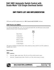
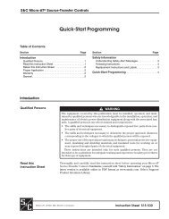
S&C Remote Supervisory Vista® Underground Distribution SwitchgearVista UDS Tank(Model 422 rated 15.5 kV, 12.5 kA symmetrical shown)B C CDimensions in inches (mm)33(838)28³⁄₄(730)36³⁄₄(933)W35(889)5¹⁄₄(133)7(178)TERMINATION VIEWSIDE VIEWEIGHT ⁵₈ (16) DIAMETERW1¹⁄₂ (38) TYPICAL3 (76) TYPICAL35(889)1⁵⁄₁₆ (33) TYPICAL26(660)8(203)1¹⁄₁₆ (27) TYPICALBCD E GFAPPROXIMATE PROJECTEDCABLE CENTER LINESANCHOR BOLT PLAN16 S&C <strong>Specification</strong> <strong>Bulletin</strong> <strong>682</strong>-<strong>31</strong>
S&C Remote Supervisory Vista® Underground Distribution SwitchgearRatingsModelkV,MaxShort-Circuit,Amperes,RMS, Sym.B C Da Ea F Ga W2012102113203213304134224<strong>31</strong>44051452362463<strong>31</strong>5.5293815.5293815.5293815.5293815.5293812 500 3ZB\zn (100) 5 (127) NA NA 3ZB\zn (100) NA 32M\zn (824)25 000 26ZZ\zn (678) 5 (127) NA NA 3ZB\zn (100) NA 55>\zn (1411)12 500 3ZB\zn (100) 5 (127) NA NA 3ZB\zn (100) NA 32M\zn (824)25 000 22Z\zn (560) 5C\v (146) NA NA 4ZC\zn (122) NA 55>\zn (1411)12 500 4ZC\zn (122) 5C\v (146) NA NA 4ZC\zn (122) NA 38B\zn (973)25 000 22Z\zn (560) 5C\v (146) NA NA 4ZC\zn (122) NA 55>\zn (1411)12 500 3ZB\zn (100) 5 (127) NA NA 3ZB\zn (100) NA 47ZC\zn (1214)25 000 11ZZ\zn (297) 5 (127) NA NA 3ZB\zn (100) NA 55>\zn (1411)12 500 3ZB\zn (100) 5 (127) NA NA 3ZB\zn (100) NA 47ZC\zn (1214)25 000 4ZC\zn (122) 5C\v (146) NA NA 4ZC\zn (122) NA 55>\zn (1411)12 500 4ZC\zn (122) 5C\v (146) NA NA 4ZC\zn (122) NA 55>\zn (1411)25 000 4ZC\zn (122) 5C\v (146) NA NA 4ZC\zn (122) NA 55>\zn (1411)12 500 3ZB\zn (100) 5 (127) 28ZB\zn (735) 7B\, (194) 3ZB\zn (100) 28ZB\zn (735) 65M\zn (1662)25 000 3ZB\zn (100) 5 (127) 28ZB\zn (735) 7B\, (194) 3ZB\zn (100) 28ZB\zn (735) 65M\zn (1662)12 500 3ZB\zn (100) 5 (127) 28ZB\zn (735) 7B\, (194) 3ZB\zn (100) 28ZB\zn (735) 65M\zn (1662)25 000 4ZC\zn (122) 5C\v (146) NA NA 4ZC\zn (122) NA 72ZC\zn (1849)12 500 4ZC\zn (122) 5C\v (146) NA NA 4ZC\zn (122) NA 72ZC\zn (1849)25 000 4ZC\zn (122) 5C\v (146) NA NA 4ZC\zn (122) NA 72ZC\zn (1849)12 500 3ZB\zn (100) 5 (127) 28ZB\zn (735) 7B\, (194) 3ZB\zn (100) 43ZB\zn (1116) 80M\zn (2043)25 000 3ZB\zn (100) 5 (127) 28ZB\zn (735) 7B\, (194) 3ZB\zn (100) 43ZB\zn (1116) 80M\zn (2043)12 500 3ZB\zn (100) 5 (127) 28ZB\zn (735) 7B\, (194) 3ZB\zn (100) 43ZB\zn (1116) 80M\zn (2043)25 000 4ZC\zn (122) 5C\v (146) NA NA 4ZC\zn (122) NA 90Z\zn (2288)12 500 4ZC\zn (122) 5C\v (146) NA NA 4ZC\zn (122) NA 90Z\zn (2288)25 000 4ZC\zn (122) 5C\v (146) NA NA 4ZC\zn (122) NA 90Z\zn (2288)12 500 3ZB\zn (100) 5 (127) 43ZB\zn (1116) 7B\, (194) 3ZB\zn (100) 43ZB\zn (1116) 95M\zn (2424)25 000 3ZB\zn (100) 5 (127) 43ZB\zn (1116) 7B\, (194) 3ZB\zn (100) 43ZB\zn (1116) 95M\zn (2424)12 500 3ZB\zn (100) 5 (127) 43ZB\zn (1116) 7B\, (194) 3ZB\zn (100) 43ZB\zn (1116) 95M\zn (2424)25 000 4ZC\zn (122) 5C\v (146) NA NA 4ZC\zn (122) NA 107B\zn (2726)12 500 4ZC\zn (122) 5C\v (146) NA NA 4ZC\zn (122) NA 107B\zn (2726)25 000 4ZC\zn (122) 5C\v (146) NA NA 4ZC\zn (122) NA 107B\zn (2726)a All four-, five-, and six-way units rated 15.5 kV and 29 kV, 12.5 kAinclude an extra 2B\,-inch (67-mm) gap between Ways Two and Three(four-way units) or between Ways Three and Four (five- and six-wayunits).S&C <strong>Specification</strong> <strong>Bulletin</strong> <strong>682</strong>-<strong>31</strong> 17
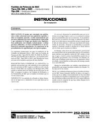
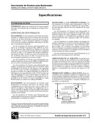
S&C Remote Supervisory Vista® Underground Distribution SwitchgearUnderCover Style Switchgear Low-Voltage EnclosureDimensions in inches (mm)1(25)1⁷⁄₁₆(37)RETRACTABLELIFTINGBRACKET48(1219)30(798)FRONT VIEW15¹⁄₂(394)SIDE VIEW15 (381) APPROXIMATE CONDUIT7 (178)ENTRANCE LOCATION2⁷⁄₈ (73)15¹⁄₂(394)7³⁄₄(197)2⁷⁄₈ (73)APPROXIMATE GROUNDROD LOCATION123 (76)30 (762)24 (610)ANCHOR BOLT PLANDOOR OPENS 115°ON A 30 (762) RADIUS1 Attach earth ground cable between the ground lug inside the low-voltageenclosure and the ground rod using copper cable of 4/0 or greaterand less than 10 feet in length.2 Ground rod must be 25 ohm impedance or less.18 S&C <strong>Specification</strong> <strong>Bulletin</strong> <strong>682</strong>-<strong>31</strong>
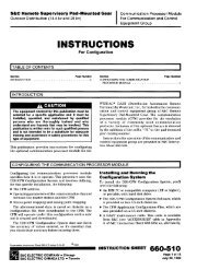
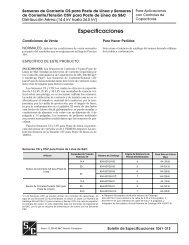
S&C Remote Supervisory Vista® Underground Distribution SwitchgearVault-Mounted Style Switchgear Low-Voltage Enclosurefor Both Wall-Mounted and Floor-Mounted TanksDimensions in inches (mm)10 (25)2 (51) 2 (51)DIA. ⁹⁄₁₆ (14) 161¹⁄₈ (29)9 (229)APPROXIMATE LOCATIONOF CONDUIT ENTRANCE8(203)3 (76)TOP VIEWR 6 (152)FOUR ⁹⁄₁₆ (14) ¹³⁄₁₆ (21) SLOTS1⁷⁄₁₆(37)RETRACTABLELIFTINGBRACKET36(914)27(686)TWO ³⁄₁₆ (5) 2 (51) 3 (76) 36 (914)STEEL CHANNEL4⁵₈(117)30 (762)34 (864)36 (914)15¹⁄₂(394)2(51)FRONT VIEWSIDE VIEWS&C <strong>Specification</strong> <strong>Bulletin</strong> <strong>682</strong>-<strong>31</strong> 19
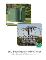
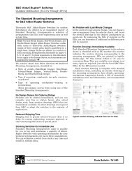
S&C Remote Supervisory Vista® Underground Distribution SwitchgearPad-Mounted Style Switchgear with Low-Voltage Compartment—Models 201, 210, and 211(Model 201 15.5 kV, 12.5 kA symmetrical shown)Dimensions in inches (mm)ANCHOR BOLT DETAIL20 S&C <strong>Specification</strong> <strong>Bulletin</strong> <strong>682</strong>-<strong>31</strong>
S&C Remote Supervisory Vista® Underground Distribution SwitchgearANCHOR BOLT PLANRatingsModelkV, MaxShort-Circuit,Amperes,RMS, Sym.D H J K L P Q W20121021115.5293812 500 61 (1549) 5 (127) 7 (178) 32ZC\zn (833) 4Z\x (114) 19Z\x (495) 15Z\x (394) 39 (991)25 000 65 (1651) 5 (127) 38C\, (975) 55>\zn (1411) 13Z\, (333) 23Z\x (597) 17Z\x (445) 79 (2007)12 500 65 (1651) 5 (127) 7 (178) 32ZC\zn (833) 4Z\x (114) 23Z\x (597) 17Z\x (445) 39 (991)25 000 65 (1651) 5C\v (146) 33C\v (857) 55>\zn (1411) 13Z\, (333) 23Z\x (597) 17Z\x (445) 79 (2007)12 500 65 (1651) 5C\v (146) 7B\, (194) 38ZB\zn (989) 4Z\x (114) 23Z\x (597) 17Z\x (445) 44 (1118)25 000 65 (1651) 5C\v (146) 33C\v (857) 55>\zn (1411) 13Z\, (333) 23Z\x (597) 17Z\x (445) 79 (2007)S&C <strong>Specification</strong> <strong>Bulletin</strong> <strong>682</strong>-<strong>31</strong> 21
S&C Remote Supervisory Vista® Underground Distribution SwitchgearPad-Mounted Style Switchgear with Low-Voltage Compartment—Models 320, 321, and 330(Model 321 15.5 kV, 12.5 kA symmetrical shown)Dimensions in inches (mm)43(1092) 36(914)2³⁄₈ (60)WPANCHOR BOLT DETAILD34⁷⁄₈(886)5(127)SIDE VIEW22 S&C <strong>Specification</strong> <strong>Bulletin</strong> <strong>682</strong>-<strong>31</strong>
S&C Remote Supervisory Vista® Underground Distribution SwitchgearANCHOR BOLT PLANRatingsModelkV, MaxShort-Circuit,Amperes,RMS, Sym.D H J K L P Q W32032133015.5293812 500 61 (1549) 5 (127) 16 (406) 47ZC\zn (1214) 13Z\x (342) 19Z\x (495) 15Z\x (394) 72 (1829)25 000 65 (1651) 5 (127) 23C\, (594) 55>\zn (1411) 13Z\, (333) 23Z\x (597) 17Z\x (445) 79 (2007)12 500 65 (1651) 5 (127) 16 (406) 47ZC\zn (1214) 13Z\x (342) 23Z\x (597) 17Z\x (445) 72 (1829)25 000 65 (1651) 5C\v (146) 16Z\x (419) 55B\, (1413) 13Z\, (333) 23Z\x (597) 17Z\x (445) 79 (2007)12 500 65 (1651) 5C\v (146) 16Z\x (419) 55B\, (1413) 13Z\, (333) 23Z\x (597) 17Z\x (445) 79 (2007)25 000 65 (1651) 5C\v (146) 16Z\x (419) 55B\, (1413) 13Z\, (333) 23Z\x (597) 17Z\x (445) 79 (2007)S&C <strong>Specification</strong> <strong>Bulletin</strong> <strong>682</strong>-<strong>31</strong> 23
S&C Remote Supervisory Vista® Underground Distribution SwitchgearPad-Mounted Style Switchgear with Low-Voltage Compartment—Models 413, 422, 4<strong>31</strong>, and 440(Model 422 15.5 kV, 12.5 kA symmetrical shown)Dimensions in inches (mm)24 S&C <strong>Specification</strong> <strong>Bulletin</strong> <strong>682</strong>-<strong>31</strong>
S&C Remote Supervisory Vista® Underground Distribution SwitchgearANCHOR BOLT PLANANCHOR BOLT DETAILModelkV,MaxRatingsShort-Circuit,Amperes,RMS, Sym.D F G H J K L N P Q W4134224<strong>31</strong>44015.5293812 500 61 (1549) 7B\, (194) 32C\zn (818) 5 (127) 7C\zn (183) 65M\zn (1662) 4B\, (117) 7Z\x (191) 19Z\x (495) 15Z\x (394) 72 (1829)25 000 65 (1651) 7B\, (194) 32C\zn (818) 5 (127) 10ZZ\zn (271) 65M\zn (1662) 8Z\, (206) 11 (279) 23Z\x (597) 17Z\x (445) 79 (2007)12 500 65 (1651) 7B\, (194) 32C\zn (818) 5 (127) 7C\zn (183) 65M\zn (1662) 4B\, (117) 7Z\x (191) 23Z\x (597) 17Z\x (445) 72 (1829)25 000 65 (1651) NA NA 5C\v (146) 7M\, (200) 72ZC\zn (1849) 4Z\x (114) 7Z\x (191) 23Z\x (597) 17Z\x (445) 79 (2007)12 500 65 (1651) NA NA 5C\v (146) 7M\, (200) 72ZC\zn (1849) 4Z\x (114) 7Z\x (191) 23Z\x (597) 17Z\x (445) 79 (2007)25 000 65 (1651) NA NA 5C\v (146) 7M\, (200) 72ZC\zn (1849) 4Z\x (114) 7Z\x (191) 23Z\x (597) 17Z\x (445) 79 (2007)S&C <strong>Specification</strong> <strong>Bulletin</strong> <strong>682</strong>-<strong>31</strong> 25
S&C Remote Supervisory Vista® Underground Distribution SwitchgearPad-Mounted Style Switchgear with Low-Voltage Compartment—Models 514 and 523(Model 514 15.5 kV, 12.5 kA symmetrical shown)Dimensions in inches (mm)ANCHOR BOLT DETAILRatingsModelkV,MaxShort-Circuit,Amperes,RMS, Sym.DF51452<strong>31</strong>5.5293812 500 61 (1549) 7B\, (194)25 000 65 (1651) 7B\, (194)12 500 65 (1651) 7B\, (194)25 000 65 (1651) NA12 500 65 (1651) NA25 000 65 (1651) NA26 S&C <strong>Specification</strong> <strong>Bulletin</strong> <strong>682</strong>-<strong>31</strong>
S&C Remote Supervisory Vista® Underground Distribution SwitchgearANCHOR BOLT PLANRatingsModelkV,MaxShort-Circuit,Amperes,RMS, Sym.G H J K L P Q W51452<strong>31</strong>5.5293812 500 39ZZ\zn (1008) 5 (127) 14ZZ\zn (373) 80M\zn (2043) 12Z\, (308) 19Z\x (495) 15Z\x (394) 102 (2591)25 000 39ZZ\zn (1008) 5 (127) 14ZZ\zn (373) 80M\zn (2043) 12Z\, (308) 23Z\x (597) 17Z\x (445) 102 (2591)12 500 39ZZ\zn (1008) 5 (127) 14ZZ\zn (373) 80M\zn (2043)) 12Z\, (308) 23Z\x (597) 17Z\x (445) 102 (2591)25 000 NA 5C\v (146) 16Z\v (413) 90Z\zn (2288) 12M\, (327) 23Z\x (597) 17Z\x (445) 113 (287012 500 NA 5C\v (146) 16Z\v (413) 90Z\zn (2288) 12M\, (327) 23Z\x (597) 17Z\x (445) 113 (287025 000 NA 5C\v (146) 16Z\v (413) 90Z\zn (2288) 12M\, (327) 23Z\x (597) 17Z\x (445) 113 (2870S&C <strong>Specification</strong> <strong>Bulletin</strong> <strong>682</strong>-<strong>31</strong> 27
S&C Remote Supervisory Vista® Underground Distribution SwitchgearPad-Mounted Style Switchgear with Low-Voltage Compartment—Models 624 and 633(Model 624 15.5 kV, 12.5 kA symmetrical shown)Dimensions in inches (mm)ANCHOR BOLT DETAIL28 S&C <strong>Specification</strong> <strong>Bulletin</strong> <strong>682</strong>-<strong>31</strong>
S&C Remote Supervisory Vista® Underground Distribution SwitchgearRatingsModelkV,MaxShort-Circuit,Amperes,RMS, Sym.D F G H J K L P Q W62463<strong>31</strong>5.5293812 500 61 (1549) 7B\, (194) 47C\zn (1199) 5 (127) 7C\zn (183) 95M\zn (2424) 4B\, (117) 19Z\x (495) 9Z\x (241) 102 (2591)25 000 65 (1651) 7B\, (194) 47C\zn (1199) 5 (127) 7C\zn (183) 95M\zn (2424) 4B\, (117) 23Z\x (597) 11Z\x (292) 102 (2591)12 500 65 (1651) 7B\, (194) 47C\zn (1199) 5 (127) 7C\zn (183) 95M\zn (2424) 4B\, (117) 23Z\x (597) 11Z\x (292) 102 (2591)25 000 65 (1651) NA NA 5C\v (146) 7B\, (194) 107B\zn (2726) 4Z\, (107) 23Z\x (597) 11Z\x (292) 113 (2870)12 500 65 (1651) NA NA 5C\v (146) 7B\, (194) 107B\zn (2726) 4Z\, (107) 23Z\x (597) 11Z\x (292) 113 (2870)25 000 65 (1651) NA NA 5C\v (146) 7B\, (194) 107B\zn (2726) 4Z\, (107) 23Z\x (597) 11Z\x (292) 113 (2870)S&C <strong>Specification</strong> <strong>Bulletin</strong> <strong>682</strong>-<strong>31</strong> 29
Printed in U.S.A.
![Boletin Descriptivo 851-30S [Spanish, 3 MB, 12/20/2004]](https://img.yumpu.com/49573007/1/190x245/boletin-descriptivo-851-30s-spanish-3-mb-12-20-2004.jpg?quality=85)

![Boletin de Especificaciones 771-31S [Spanish, 2 MB, 8/30/2010]](https://img.yumpu.com/48742025/1/190x245/boletin-de-especificaciones-771-31s-spanish-2-mb-8-30-2010.jpg?quality=85)