KEP Operator Interfaces INDEX - Norman Equipment Co.
KEP Operator Interfaces INDEX - Norman Equipment Co.
KEP Operator Interfaces INDEX - Norman Equipment Co.

You also want an ePaper? Increase the reach of your titles
YUMPU automatically turns print PDFs into web optimized ePapers that Google loves.
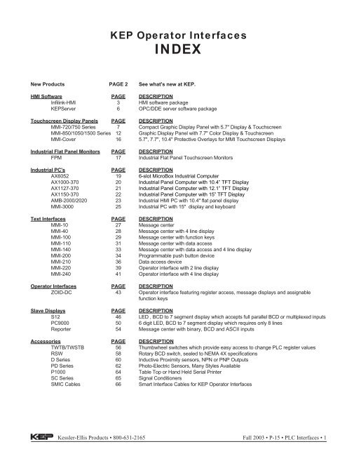
New ProductsAX60526-slot MicroBoxIndustrial <strong>Co</strong>mputerAX1000-370See Page 18 for DetailsIndustrial Panel <strong>Co</strong>mputerwith 10.4" TFT DisplayAX1127-370See Page 19 for DetailsIndustrial Panel <strong>Co</strong>mputerwith 12.1" TFT DisplayAX1150-370See Page 20 for DetailsIndustrial Panel <strong>Co</strong>mputerwith 15" TFT DisplayMMI-7xx-CASE-ARMSee Page 21 for DetailsMounting Accessory for MMI-720and MMI-750NEMA4 Enclosure with Mounting ArmSee Page 9 for Details2 • PLC <strong>Interfaces</strong> • Fall 2003 • P-15 Kessler-Ellis Products • 800-631-2165
INFILINK-HMIFeatures• Free Design Mode: Only pay to unlock runmodecopies• OPC Client Functionality• E-mail and Web Enabled: Send e-mail andView tag data over the InternetIndustrial Automation Software• Historical Trending, Alarming, Data Loggingincluded in base price• Email and Web Enabling included in baseprice• No yearly “maintenance” or “support” feesHMI SoftwareDescription:Infilink-HMI is a full featured solution at an affordableprice. It is ideal for the small PLC user with its easy setupand run time price half that of competitive products.Machine builders and users want the benefits of aWindows based package, but are held back by thepremium prices demanded by many vendors. Infilink-HMIchanges all of that with the truly affordable HMI, Infilink-HMI.Features Added to the New Version of Infilink-HMI• OPC Client Functionality• E-mail and Web Enabled: Send e-mail and Viewtag data over the Internet• Historical and Alarm Data Logging to MS Access(MDB) FilesOther Important Features of Infilink-HMI:• Free Design Mode: Only pay to unlock run-modecopies• Historical Trending, Alarming, Data Loggingincluded in base price• Email and Web Enabling included in base price• No yearly “maintenance” or “support” fees• Built In Scheduler• OPC, DDE, NetDDE & AdvancedDDE SupportEmail CapableInfilink-HMI can sendemail messages basedon alarm conditions. Thiscan be a regular emailmessage, or it could besent to a technician'salphanumeric pager.SchedulerInfilink-HMI nowincludes a builtin scheduler.Events can takeplace or tag datacan be changedbased on time,date, day ofweek, or holiday.New events can be entered by the operator in Run modethrough the calendar interface.Infilink-HMI <strong>Co</strong>mmunicates Using <strong>KEP</strong>ServerEX• One free driver included with Infilink-HMI purchase.• OPC and DDE supported.• Over 100 drivers available.• Support for various fieldbus networks includingEthernet TCP/IP and DeviceNet.Web EnabledUse the internet and ourInfiviewer utility to viewtag data. This is anespecially powerfultroubleshooting featurewhen combined withemail going to an alphanumericpager. Infilinkcan notify technicalpersonnel of a problemvia email, and give themthe ability to obtainadditional applicationinformation over theinternet.Kessler-Ellis Products • 800-631-2165 Fall 2003 • P-15 • PLC <strong>Interfaces</strong> • 3
<strong>KEP</strong> ServerEXHigh PerformanceOPC Server SoftwareHMI SoftwareDescription<strong>KEP</strong>ServerEX is the latest generation of <strong>KEP</strong>ware's OPCserver technology. Building upon the original <strong>KEP</strong>server,<strong>KEP</strong>ServerEX has incorporated many of the features requestedby <strong>KEP</strong>ware's customers. In addition to customer drivenenhancements, many technological changes have occurred.These features and enhancements have all been made with thegoal of providing an OPC server that demonstrates unparalleledcompatibility and performance. A few of the enhancements aretransparent to the user, but there are a number of new featuresthat are readily apparent and directly available to the user. Thefollowing sections will describe the primary features of<strong>KEP</strong>ServerEX.Application <strong>Co</strong>nnectivity<strong>KEP</strong>ServerEX supports the following client server technologies:OPC Data Access Version 1.0a & 2.0DDE Format CF_Text, XL_Table & AdvancedDDEDevice <strong>Co</strong>nnectivity<strong>KEP</strong>ServerEX allows you to use a number of communicationsdrivers concurrently.Runs as NT Service<strong>KEP</strong>ServerEX supports running as a service under WindowsNT/2000. Service operation is completely user configurablefrom the Tools|Options menu and can be changed at any timeallowing you to move from normal stand alone programoperation to NT service mode.Data Scaling<strong>KEP</strong>ServerEX now supportsdirect scaling of device data.Scaling allows raw device datato be converted to engineeringunits for OPC client applications.<strong>KEP</strong>ServerEX provides anumber of unique scalingfeatures that make it easy toimplement scaling in yourapplication.On-Line Full TimeThe full time on-line mode of operation allows a <strong>KEP</strong>ServerEXproject to be modified while the server continues to supply datato client applications. Almost every parameter can be changedwhile the server is operating.User Management<strong>KEP</strong>ServerEX includes a built-in UserManager that allows complete controlover what types of functionality eachindividual user can access.Tag Management<strong>KEP</strong>ServerEX's new user defined tag management featuresallow you to create a tag database structure that fits the natureof your application.Automatic Tag Database GenerationThe Automatic Tag DatabaseGeneration feature brings OPCtechnology one step closer to Plug andPlay operation. Drivers that supportthis feature can either read taginformation directly from a device orgenerate tags from stored tag data.Diagnostics<strong>KEP</strong>ServerEX's new diagnosticfeatures provide real-time data onthe performance of yourcommunication driver. All read andwrite operations can be viewed inthe diagnostic display window of<strong>KEP</strong>ServerEX or can be trackeddirectly in your OPC clientapplication by using its built-in diagnostic tags.Modem Support<strong>KEP</strong>ServerEX supports the use of modems on all serialcommunication drivers. Modem control is provided by a set ofnew modem tags.OPC Quick Client<strong>KEP</strong>ServerEX includes anextensive OPC Quick Clientapplication to aid in thedevelopment of your OPCapplications.System Requirements:MinimumVisual Basic ExamplesThe simple and complex VBexamples included with<strong>KEP</strong>ServerEX are wellcommented and provideadditional pointers for usingOPC servers in your VBapplications.RecommendedOperating System: Windows 98 Windows NT 4.0 SP5or betterProcessor: Pentium 200Mhz Pentium 400MhzRam: 32 MB 64 MBDisk Space: 10 MB 10 MBNOTE: While <strong>KEP</strong>ServerEX will run on Windows 95 andWindows 98 we strongly recommend the use of eitherWindows NT 4.0 SP5 or Windows 2000 for use inindustrial applications.For More Information call <strong>KEP</strong>ware, Inc.<strong>KEP</strong>ware • 60 Forest Falls Drive • Suite 5 • Yarmouth, Maine 04096Phone: 207-846-5881 • Fax: 207-846-5947 • http://www.OPCSource.com6 • PLC <strong>Interfaces</strong> • Fall 2003 • P-15 Kessler-Ellis Products • 800-631-2165
MMI-720/750Graphic Display Panel andTouch ScreenFeatures• LCD Graphic Display with Touch Panel• 5.7" Displays, TFT <strong>Co</strong>lor, STN <strong>Co</strong>lor orGrayscale• <strong>Co</strong>nnects to Today’s Popular PLC’s via SingleCable to Programming Port• FREE Design Mode, Windows based SetupSoftware Included• 24 VDC PoweredTouchscreen Display PanelsLCD with Touch PanelThe MMI-720/750 is a touch screen interface for programmablecontrollers. It connects directly to most PLCs and doesnot require the PLC to run any special program for datacommunication. This greatly reduces PLC programming time.The units display pictorial information, data and messages thatare preloaded into it using a Personal <strong>Co</strong>mputer. Touch screenareas can be programmed to perform various functions. Freesetup software for configuring the MMI-720/750 is includedwith each unit. The Easy Builder Screen Editor Software takesadvantage of Microsoft Windows graphical interface and objectoriented scheme. It offers fast and intuitive configuration. Thissimplifies application design while reducing developmentcosts. It is designed especially for harsh working environments.<strong>Co</strong>nnect directly to most PLCsThe MMI-720/750 uses each PLC’s communication protocol toread or write data. It does not require the PLC to run anyspecial program for data communication. The MMI-720/750allows the user to optimize communications by selecting thedata block size that is uploaded with each communication tothe PLC. The EasyWindow utility that is provided along withEasyBuilder can be used to further monitor and tweak PLCcommunication efficiencies.PLC Driver:More supporting device drivers are being developed every day.AB DF1AB DH485AB PLC5AB Logix DF1DELTA DVPENTERTRON MODBUS RTUFACON FBFuji NB SeriesGE FANUC SNP-XHITACHI EH-150IDEC Micro 3IDEC OpenNETINDUSTRIAL <strong>INDEX</strong>INGSYSTEMS, INC.Jetter NanoKeyence KV-16DTKOYO DirectLenzeLG GLOFA CnetLG Master KMatsushita FP (Aromat)MITSUBISHIMODICON MODBUS RTUMODBUS RTU TCP/IPOMRONSAIA PCDSamsung SPC-10Sharp JW SeriesSIEMENS S7-200SIEMENS S7/300SIMATIC TI505Telemecanique UnitelwayToshiba T SerialVIGOR M SeriesYokogawa PLC SeriesMore supporting device drivers are being developed every day.Kessler-Ellis Products • 800-631-2165 Fall 2003 • P-15 • PLC <strong>Interfaces</strong> • 7
HMI Software8 • PLC <strong>Interfaces</strong> • Fall 2003 • P-15 Kessler-Ellis Products • 800-631-2165
Easy Setup with EasyBuilder SoftwareEasyBuilder is a graphics editor software program for configuring the MMI Series. EasyBuilder can be downloaded for free from<strong>KEP</strong>’s website (www.kep.com). Typical projects are composed of user defined windows. Each window is composed of a varietyof elements called objects. There are drawing objects or putting static text and graphics on the window and Part objects forputting active objects on a window. PLC controlled objects can be used for window control and system functions.<strong>Co</strong>nfiguration of the MMI-720/750 is easy. To setup objects, select an icon from the toolbox, a dialog box appears. Fill in objectattributes requested by the dialog to complete the object setup process. Move the object to the right position and drag theboundary of the object. It’s a straightforward, simple, and consistent process.Animation Tools:Bit Lamp – Place an indicator that is bit triggeredWord Lamp – Place an indicator that is word triggeredSet Bit – Set a bitSet Word – Set a wordToggle Switch – Toggle a bitMultiState Switch – Increment/Decrement a wordFunction Button – Perform a system operationNumeric Input Extend – Display/Change digital dataNumeric Display – Display digital dataASCII Input Extend – Display/Change alphanumeric dataASCII Display – Display alphanumeric dataX,Y Move Animation – Move an object via pixel coordinatesSpot Move Animation – Move an object on a predefined pathDirect Window - Popup Window on BitPopup Window on RegisterAlarm DisplayTrend GraphXY PlotBarGraphMeterScrolling AlarmEvent DisplayRecipe Transfer(requires option card)PLC <strong>Co</strong>ntrols: Screen,backlight, printerData TransferTouchscreen Display PanelsKessler-Ellis Products • 800-631-2165 Fall 2003 • P-15 • PLC <strong>Interfaces</strong> • 9
HMI SoftwareGraphics can be produced by using the EasyBuilders own setof drawing tools. You can import any 256 color BMP formatgraphic into EasyBuilder to customize your application. ScreenCaptures and Graphics may also be cut and pasted intoPaintbrush for conversion to the BMP format. Libraries withover 300 commonly used graphics are included withEasyBuilder Software. These libraries can be edited and newlibraries created to hold new graphics you have createdDrawing Tools:Line – Draw straight linesRectangle – Draw squares and rectanglesEllipse – Draw circles and ellipsesArc – Draw 90-degree arcsPolygon – Draw multisided objectsText – Place static textScale – Place lines at regular intervalsShape – Place a static shape from a libraryBitmap - Place a static bitmap from a libraryOther convenient features include: The ability tocopy windows and objects between projects.Windows can be stacked (overlapped) to reduceduplicate objects. Tags can be assigned to Datapoints for easy reference during project development.Labels that change depending on languageuse can also be incorporated into the project givingit international compatibility. Macro scripts can betriggered by bit actions to perform calculations,data manipulation and logical operations. Up to256 scripts can be programmed into the unit. Theability to put a system bar (Taskbar) at the bottomof the screen to emulate familiar graphic interfaceoperations.After completing a project it can be simulated offlineto view approximately how your project willlook and respond. There is also an on-line simulation.<strong>Co</strong>nnect the PC to your MMI unit and connectthe MMI to your PLC. The MMI display is emulatedon the PC screen by using the MMI as a bridge togo to your PLC. The PC will mimic exactly how theMMI will respond once the project is downloaded.To download a project, connect the MMI-720/750 to COM1 or COM2 port of your PC using the download cable provided with theunit. Execute the download function, it will directly transfer your project data to the MMI-720/750’s flash memory.The Ethernet Option package includes expanded memory, a compact card memory slot , an additional printer port and a 10baseT ethernet port. The compact card slot allows a user to update the project in a unit without connecting a computer or someother programming device. The printer port can be used to print out screen captures and event or alarm information. Theethernet port can be used for unit to unit communications or Modbus TCP/IP communications to controllers.10 • PLC <strong>Interfaces</strong> • Fall 2003 • P-15 Kessler-Ellis Products • 800-631-2165
MMI-7xx-CASE-ARM AccessoryHere's a practical and convenient mounting solution foryour MMI-720 & MMI-750 graphical touchscreens. ANEMA 4 Enclosure & Mounting Arm offers washdownresistance and positioning flexibility, and improvesoperator utilization.This Option is available for MMI-720 and MMI-750modelsTouchscreen Display PanelsArm Dimensions:Enclosure Dimensions:ORDERING INFORMATION:Part NumberMMI-720MMI-750MMI-750TDescriptionGraphic Interface with 5.7" blue, 4 grey scale, LCD display and TouchscreenGraphic Interface with 5.7" STN, 256 color, LCD display and TouchscreenGraphic Interface with 5.7" TFT, 256 color display & touchscreenOptions:HB Enhanced display for daylight viewing (MMI750T only)AccessoriesMMI-7xx-CASE-ARM Mounting OptionMMI-PDK includes printed manual, programming cable and setup CD.Note: Setup software and programming cable are included with each unit. The manual is on the CD as a PDF file. A printed copyof the manual is sent with each MMI-TS product order.Kessler-Ellis Products • 800-631-2165 Fall 2003 • P-15 • PLC <strong>Interfaces</strong> • 11
MMI-850/1050/1500Graphic Display Panels andTouch ScreensTouchscreen Display PanelsFeatures• LCD Graphic Display with Touch Panel• 7.7", 9.4" and 10.4" Displays, TFT <strong>Co</strong>lor, STN<strong>Co</strong>lor or Monochrome• <strong>Co</strong>nnects to Today’s Popular PLC’s via SingleCable to Programming Port• FREE Design Mode, Windows based SetupSoftware Included• 24 VDC PoweredLCD with Touch PanelThe MMI-850/1050/1500 are touch screen interfaces forprogrammable controllers. They connect directly to most PLCsand do not require the PLC to run any special program for datacommunication. This greatly reduces PLC programming time.The units display pictorial information, data and messages thatare preloaded into them using a Personal <strong>Co</strong>mputer. Touchscreen areas can be programmed to perform various functions.Free setup software for configuring the MMI-850/1050/1500 is included with each unit. The Easy Builder ScreenEditor Software takes advantage of Microsoft Windowsgraphical interface and object oriented scheme. It offers fastand intuitive configuration. This simplifies application designwhile reducing development costs. They are designed especiallyfor harsh working environments.<strong>Co</strong>nnect directly to most PLCsThe MMI-850/1050/1500 uses each PLC’s communicationprotocol to read or write data. They do not require the PLC torun any special program for data communication. The MMI-850/1050/1500 allows the user to optimize communications byselecting the data block size that is uploaded with eachcommunication to the PLC. The EasyWindow utility that isprovided along with EasyBuilder can be used to furthermonitor and tweak PLC communication efficiencies.PLC Driver:More supporting device drivers are being developed every day.AB DF1AB DH485AB PLC5AB Logix DF1DELTA DVPENTERTRON MODBUS RTUFACON FBFuji NB SeriesGE FANUC SNP-XHITACHI EH-150IDEC Micro 3IDEC OpenNETINDUSTRIAL <strong>INDEX</strong>INGSYSTEMS, INC.Jetter NanoKeyence KV-16DTKOYO DirectLenzeLG GLOFA CnetLG Master KMatsushita FP (Aromat)MITSUBISHIMODICON MODBUS RTUMODBUS RTU TCP/IPOMRONSAIA PCDSamsung SPC-10Sharp JW SeriesSIEMENS S7-200SIEMENS S7/300SIMATIC TI505Telemecanique UnitelwayToshiba T SerialVIGOR M SeriesYokogawa PLC SeriesMore supporting device drivers are being developed every day.12 • PLC <strong>Interfaces</strong> • Fall 2003 • P-15 Kessler-Ellis Products • 800-631-2165
Kessler-Ellis Products • 800-631-2165 Fall 2003 • P-15 • PLC <strong>Interfaces</strong> • 13Touchscreen Display Panels
Easy Setup with EasyBuilder SoftwareEasyBuilder is a graphics editor software program for configuring the MMI Series. EasyBuilder can be downloaded for free from<strong>KEP</strong>’s website (www.kep.com). Typical projects are composed of user defined windows. Each window is composed of a varietyof elements called objects. There are drawing objects or putting static text and graphics on the window and Part objects forputting active objects on a window. PLC controlled objects can be used for window control and system functions.Touchscreen Display Panels<strong>Co</strong>nfiguration of the MMI-1500/1050/850 is easy. To setup objects, select an icon from the toolbox, a dialog box appears. Fill inobject attributes requested by the dialog to complete the object setup process. Move the object to the right position and drag theboundary of the object. It’s a straightforward, simple, and consistent process.Animation Tools:Bit Lamp – Place an indicator that is bit triggeredWord Lamp – Place an indicator that is word triggeredSet Bit – Set a bitSet Word – Set a wordToggle Switch – Toggle a bitMultiState Switch – Increment/Decrement a wordFunction Button – Perform a system operationNumeric Input Extend – Display/Change digital dataNumeric Display – Display digital dataASCII Input Extend – Display/Change alphanumeric dataASCII Display – Display alphanumeric dataX,Y Move Animation – Move an object via pixel coordinatesSpot Move Animation – Move an object on a predefined pathDirect Window - Popup Window on BitPopup Window on RegisterAlarm DisplayTrend GraphXY PlotBarGraphMeterScrolling AlarmEvent DisplayRecipe Transfer(requires option card)PLC <strong>Co</strong>ntrols: Screen,backlight, printerData TransferGraphics can be produced by using the EasyBuilder’s own setof drawing tools. You can import any 256 color BMP formatgraphic into EasyBuilder to customize your application. ScreenCaptures and Graphics may also be cut and pasted intoPaintbrush for conversion to the BMP format. Libraries withover 300 commonly used graphics are included withEasyBuilder Software. These libraries can be edited and newlibraries created to hold new graphics you have created.Drawing Tools:Line – Draw straight linesRectangle – Draw squares and rectanglesEllipse – Draw circles and ellipsesArc – Draw 90-degree arcsPolygon – Draw multisided objectsText – Place static textScale – Place lines at regular intervalsShape – Place a static shape from a libraryBitmap - Place a static bitmap from a library14 • PLC <strong>Interfaces</strong> • Fall 2003 • P-15 Kessler-Ellis Products • 800-631-2165
Other convenient features include: The ability to copy windows and objects between projects. Windows can be stacked (overlapped)to reduce duplicate objects. Tags can be assigned to Data points for easy reference during project development. Labelsthat change depending on language use can also be incorporated into the project giving it international compatibility. Macroscripts can be triggered by bit actions to perform calculations, data manipulation and logical operations. Up to 256 scripts can beprogrammed into the unit. The ability to put a system bar (Taskbar) at the bottom of the screen to emulate familiar graphicinterface operations.After completing a project it can besimulated off-line to view approximatelyhow your project will look and respond.There is also an on-line simulation.<strong>Co</strong>nnect the PC to your MMI unit andconnect the MMI to your PLC. The MMIdisplay is emulated on the PC screen byusing the MMI as a bridge to go to yourPLC. The PC will mimic exactly how theMMI will respond once the project isdownloaded.To download a project, connect the MMI-1500/1050/850 to COM1 or COM2 port ofyour PC using the download cable providedwith the unit. Execute the downloadfunction, it will directly transfer your projectdata to the MMI-1500/1050/850’s flashmemory.Touchscreen Display PanelsThe Ethernet Option package includes expanded memory, a compact card memory slot , an additional printer port and a 10BaseT ethernet port. The compact card slot allows a user to update the project in a unit without connecting a computer or someother programming device. The printer port can be used to print out screen captures and event or alarm information. Theethernet port can be used for unit to unit communications or Modbus TCP/IP communications to controllers.ORDERING INFORMATION:Part NumberMMI-850MMI-1050MMI-1500TDescriptionGraphic Interface with 7.7" STN, 256 color, LCD display and TouchscreenGraphic Interface with 9.4" blue, 4 gray scale, LCD display and TouchscreenGraphic Interface with 10.4" TFT, 256 color display and TouchscreenAccessoriesMMI-PDK includes printed manual, programming cable and setup CD.Note: Setup software and programming cable are included with each unit. The manual is on the CD as a PDF file. A printed copyof the manual is sent with each MMI-TS product order.Kessler-Ellis Products • 800-631-2165 Fall 2003 • P-15 • PLC <strong>Interfaces</strong> • 15
MMI-COVER5.7, 7.7, 10.4”Protective OverlaysFeatures• LCD Graphic Display with Touch PanelTouchscreen Display Panels• Protects against scratches, grime, and fingerprints• Chemical resistant.• Designed to fit the MMI Touchscreen SeriesIntroductionThe protective sheet adds a clear protective shield to yourMMI touchscreen. Each protective screen comes with apeel-off film on the front to prevent scratching and a peelofffilm in the back to protect the adhesive around theperimeter.SpecificationsMaterial: Polyester film.Chemical resistance:Resistant to:AlcoholsDilute AcidsDilute AlkalisEstersHydrocarbonsKetonesDimensions (W x H x D):MMI-7XX-COVER (for MMI720/750):183 x 129 x 0.18mmMMI-8XX-COVER (for MMI850):219 x 164 x 0.18mmMMI-15XX-COVER (for MMI1500S/T):294 x 217.3 x 0.18mmOrdering InformationMMI-7XX-COVER: (for MMI720/750 Series)Protective Sheet 5 sheets per package.MMI-8XX-COVER: (for MMI850 Series)Protective Sheet 5 sheets per package.MMI-15XX-COVER: (for MMI1500Series)Protective Sheet 3 sheets per package.16 • PLC <strong>Interfaces</strong> • Fall 2003 • P-15 Kessler-Ellis Products • 800-631-2165
FPM SeriesFeatures:• Mounting Bezel is Sealed to NEMA 4/12• Screen Setup is Handled Through an Easy-To-UseRear-Mounted Membrane Keypad (tamperproof)• Bezel is Finished With a Tough Baked-On Powder<strong>Co</strong>at Resistant to Scratches and Most Chemicals• <strong>Co</strong>mpatible With Standard <strong>Co</strong>mputer Video Cards• All Video Settings are Stored in Non-VolatileMemory and Retained During Power Loss• Multi-Frequency Capability and Internal ScalingEngine Provide Sharp Full Screen Display ofStandard PC Video Display Signals• High Quality LCD Suitable for Harsh Lighting<strong>Co</strong>nditions and Off-Angle Viewing• Displays are Fitted With High Resolution AnalogResistive Touch Screen, Available Either as a SerialRS-232 Interface or PC Bus Card• Touch Screen Provides Mouse Emulation,Supporting Click, Double Click, and Click andDrag...With Right Click Functionality!• Hinged Rear Panel for Easy Access During ServiceIndustrial Flat PanelTouch-Screen Monitors• Stainless Steel <strong>Co</strong>rrosion Resistance Chassis• Bezel is Milled from .250”-thick 6061 AluminumPlate.• Wide Ranging (90-246 VAC) Auto SwitchingIndustrial Grade Power Supplies.FLAT PANEL MONITORSDescription:Monitors for industrial computers have changed.Those big, clunky boxes are being replaced by slimprofileversions. These screens not only free up valuablebenchtop or floor space, they also enhance the company’simage with their leaner and cleaner high tech look.Kessler-Ellis Products offers a range of 7 different sizesto fit any space requirement — from a mini 6.4” up to ahuge 20”. These touch-screens are ruggedly constructedwith a chassis of 16-gauge stainless steel, for NEMAratedperformance in harsh industrial environments.Operating temperature range is from 0 to 50° C andhumidity levels of up to 95%. All models can becustomized cosmetically to user requirements, includingcolor match-ups and inclusion of company logos onmounting bezels.Part NumberFPM-64TFPM-104TFPM-120TFPM-150TFPM-170TFPM-180TOrdering InformationDescription6.4” TFT Display with Touch Screen10.4” TFT Display with Touch Screen12.1” TFT Display with Touch Screen15.1” TFT Display with Touch Screen17.1” TFT Display with Touch Screen18.1” TFT Display with Touch ScreenThe above products include VGA cable, DB9 cable fortouchscreen, power cable, and CD with ELO touchscreendriver. These displays all feature a heavy black powercoated aluminum bezel and premium high brightness andhigh viewing angle TFT display panels. Mounting is bymeans of studs on the back of the bezel, nuts included.Kessler-Ellis Products • 800-631-2165 Fall 2003 • P-15 • PLC <strong>Interfaces</strong> • 17
FLAT PANEL MONITORSDisplay Size/TypeActive AreaPixel FormatBrightness<strong>Co</strong>ntrast RatioViewing Angle (horiz.)Viewing Angle (Vert.)Back Light Life<strong>Co</strong>lors SupportedBezel Outside Dim.Bezel MaterialBezel FinishFront End <strong>Co</strong>nst.Chassis Depth(Behind Cabinet Door)Chassis <strong>Co</strong>nstructionOperating Temp.Storage TempOperating HumidityStorage HumidityInput VoltageInput WattageAnalog ResistiveTouch Screen Res.Screen FinishChemical ResistanceEstimated Life<strong>Co</strong>mputer InterfaceElectrostatic ProtectionGENERAL SPECIFICATIONSFPM-64 / 64T FPM-104 / 104T FPM-120 / 120T FPM-140 / 140T FPM-150 / 150T FPM-180 / 180T FPM-200 / 200T6.4" Display 10.4" Display 12.1" Display 14" Display 15" Display 18" Display 20.1" DisplayLIQUID CRYSTAL DISPLAY (LCD)6.4" Diagonal/TFT 10.4" Diagonal/TFT 12.1" Diagonal/TFT 14" Diagonal/TFT 15.1" Diagonal 18.1" Diagonal 20.1" Diagonal/TFTActive Matrix Active Matrix Active Matrix Matrix Active Matrix5.14" (h) x 3.82" (v) 8.31" (h) x 6.25" (v) 9.69" (h) x 7.25" (v) 11.19" (h) x 8.39" (v) 11.97" (h) x 8.98" (v) 14.135"(h) x 11.310"(v) 15.72" (h) x 12.58" (v)640(h) x 480(v) 800(h) x 600(v) 640(h) x 480(v) 640(h) x 480(v)800(h) x 600(v)800(h) x 600(v)1024(h) x 768(v)1024(h) x 768(v)1280(h) x 1024(v)300 Nits Typical 400 Nits Typical 300 Nits Typical 200+ Nits Typical 200 Nits Typical 150 Nits Typical100:1 300:1 200:1 150:1 >150:1 300:1 150:170/70 Deg. 60/60 Deg. 70/70 Deg. 80/80 Deg.70/40 Deg. 45/55 Deg. 50/40 Deg. 70/70 Deg. 60/60 Deg. 80/80 Deg.50,000 Hours (half life)256,000 16 Million with color 16 Million with color 16 Millionenhancement on enhancement (standard (full color analog LCD)(Standard) controller function)MECHANICAL CONSTRUCTION9.5" (h) x 7.0" (v) 13.13" (h) x 11.08" (v) 15" (h) x 12.5" (v) 16.5" (h) x 13.64" (v) 17.564"(h) x 14.563"(v) 18.927"(h) x 14.563"(v) 21.5" (h) x 18.3" (v).250" 6061 AluminumBlack Textured Powder <strong>Co</strong>atNEMA 4/122.125" 1.125" 4.125".16 Ga. Stainless SteelENVIRONMENTAL0-50° C0-60° C10-95% Non <strong>Co</strong>ndensing10-95% Non <strong>Co</strong>ndensingELECTRICAL12 VDC Nominal 90-264 VAC Auto Switching25 Watts Typical 35 Watts Typical 50 Watts Typical 60 Watts Typical(75 Watt Power Supply)TOUCH SCREEN5 Wire400 ppiAnti ReflectiveAcetone, MEK, Mineral spirits, Isopropyl alcohol, Methylene chloride>35 Million touches in one locationSerial RS-232 (Standard) PC-Bus (optional)IEC-801-218 • PLC <strong>Interfaces</strong> • Fall 2003 • P-15 Kessler-Ellis Products • 800-631-2165
Features• Desktop or wallmount industrial computer• Supports up to 6 full-size cards• One 5.25" and three 3.5" drive bays• Flexible drive bay design for ease ofmaintenance• Equipped with a 150W power supply• CDROM Drive• Floppy Disk DriveAX60526-slot MicroBoxIndustrial <strong>Co</strong>mputerSpecifications:Standard <strong>Co</strong>lor Black<strong>Co</strong>nstruction Heavy-duty cold-rolled steelDrive Capacity Exposed 1 x 5.25" and 1 x 3.5"drivesInternal 2 x 3.5" drives<strong>Co</strong>oling One 8cm ball-bearing fan(42.5CFM/each) with aremovable filterFront Panel Indicators1 x power on/off; 1 x HDDFront Panel <strong>Co</strong>ntrols1 x power on/off; 1 x systemresetPre-punched PanelFront1 x DIN 5-pin keyboardRear1 x 9-pin; 1 x 25-pinSystem Board SBCCPUCeleron 533MHzRAM64MBExpansions 6-slot backplaneSpeaker One 0.4W speakerOperating Temperature RangeOS Supported32° to 122° F (0° to 50° C)Windows 98, Windows NT,Windows 2000, Windows XPDimensions (W x D x H)7.5"(191.42mm) x16.2"(412mm) x9.7"(246.5mm)Ordering Information:BOXPC-WALL-AX60526-slot Industrial <strong>Co</strong>mputer with PICMG backplaneIncludes:150W power supply10 GB HDD256 MB RAM6 slot backplane1 GHz Pentium III Celeron CPUWindows 2000 Professional Operating SystemCD Read/Write DriveFloppy DriveSerial, Printer, USB, VGA, Ethernet PortsOptions:512MBNTWW98XP512MB RAMWindows NT WorkstationWindows 98SEWindows XP Professional<strong>Co</strong>nsult factory for the latest configuration options.Industrial PC'sKessler-Ellis Products • 800-631-2165 Fall 2003 • P-15 • PLC <strong>Interfaces</strong> • 19
AX1000-370Features• 10.4" TFT 250nit VGA LCD• NEMA 4/12 Front Bezel• Resistive Type of Touch Screen• One Half-size PCI/ISA Card ExpansionIndustrial Panel <strong>Co</strong>mputerwith 10.4” TFT DisplayIndustrial PC'sSpecifications:<strong>Co</strong>nstructionDisplayOn Board Graphics:CPURAMMemory ExpansionIP 65, NEMA 4/12 Rugged Protection10.4" TFT; Brightness: 250nitView angle: U/D: 150°, R/L: 120°Resolution: 640 x 4801X AGP; 2MB SDRAM GraphicMemoryCeleron 533MHz64MBOne 168-pin DIMM Socket Up to256MB SDRAMSerial Ports RS-232 x 3; RS-232/422/485 x 1+5V/+12V power output capability bypin 1 and pin 9 (selectable via jumpersetting)Parallel Port SPP/EPP/ECP supported; <strong>Co</strong>nfigurableto LPT1, LPT2, LPT3 or disablePS/2 <strong>Interfaces</strong> PS/2 mouse x 1; PS/2 keyboard x 1DIO4 channel bits of TTL/DTL compatibleDigital input and digital outputDiskOnChip Support M-systems Flash diskHard Disk Drive enhanced IDE interface 2.5" typeFloppy Disk Drive 1.44MB, super slim typeLAN 32 bit PnP Ethernet controller 10/100Base-T (RJ-45)Watchdog Timer 64 levels timer with time-out intervalsfrom 0.5 - 1600 sec.<strong>Co</strong>nnectors D-Sub 9 pin x 1 (male) for RS-232 /RS-422 / RS-485; D-Sub 9 pin x 3(male) for RS-232 (One port reserve fortouch screen); D-Sub 25 pin x 1(female) for Parallel; D-Sub 15 pin x 1(male) for digital I/O; P/S 2 x 2 forKeyboard and Mouse; RJ-45 x 1 forEthernet; D-Sub 37 pin (female) forexternal floppy disk drive; D-Sub 15 pinx 1 (female) for S-VGA outputExpansion Slot ISA x 1 / PCI x 1 Share PC/104 x 1DimensionsWeightOS Supported12.99"(330mm)(W) x 2.87"(73mm)(D) x10.47"(266mm)(H); Front PANELThickness: 8mm4.3 KgWindows 98, Windows NT, Windows2000, Windows XPOperation Temp. 32° to 122° F (0° to 50° C)Relative Humidity 5% - 95%, non-condensingOrdering Information:AX1000-37010.4" TFT Industrial Panel <strong>Co</strong>mputerIncludes:100W power supply10 GB HDD64MB RAM1 slot backplane533 MHz Celeron CPUWindows 2000 Professional Operating SystemOptions:T128MB256MB512MBCD850MHz1GHzNTWW98XPCDRWTouchscreen, Analog Resistive Type128MB RAM256MB RAM512MB RAMInternal CDROM Drive850MHz Pentium III CPU1GHz Intel Celeron CPUWindows NT WorkstationWindows 98SEWindows XP ProfessionalCDROM R/W Drive<strong>Co</strong>nsult factory for the latest configuration options.20 • PLC <strong>Interfaces</strong> • Fall 2003 • P-15 Kessler-Ellis Products • 800-631-2165
AX1127-370Features• 12.1" TFT 250nit SVGA LCD• NEMA 4/12 Front Bezel• Resistive Type of Touch Screen• Build-in Super Slim type of CD-ROMor CD-RW• Build-in 3.5" IDE type HDD• One Half-size PCI/ISA Card ExpansionIndustrial Panel <strong>Co</strong>mputerwith 12.1” TFT DisplaySpecifications:Front Bezel IP 65, NEMA 4/12 Rugged ProtectionDisplay12.1" TFT; Brightness: 250nitView Angle: U/D: 150°Resolution: 800 x 600CPUCeleron 533MHzRAM64MBBus Clock66/100MHzMemory Expansion One 168-pin DIMM socket up to 256MBSDRAMOnboard Graphics C&T 69000 1X AGP; 2MB SDRAMGraphic memoryDIO4 channel bits of TTL/DTL compatibleDigital input/outputDiskOnChip Support M-systems flash diskHard Disk Drive Enhanced IDE interface 3.5" typeLAN 32 bit PnP Ethernet controller 10/100Base-T (RJ-45)Watchdog Timer 64 levels timer with time-out intervalsfrom 0.5 - 1600Serial Port RS-232 x 3; RS-232/422/485 x 1+5V/+12V power output capability bypin 1 and pin 8, (selectable via jumpersetting)ParallelSPP/EPP/ECP supported; <strong>Co</strong>nfigurableto LPT1, LPT2, LPT3 or disableI/O <strong>Co</strong>nnectors D-Sub 9-pin x 1 (male) for RS-232/RS-422/RS-485; D-Sub 9-pin x 3 (male) forRS-232 (One port reserve fortouchscreen); D-Sub 25-pin x 1(female) for parallel; D-Sub 15-pin x 1(male) for DIO; PS/2 x 2 for keyboardand mouse; RJ-45 x 1 for Ethernet; D-Sub 15-pin x 1 (female) for S-VGAoutput; Centronic 26-pin (female) forexternal floppy disk drive; Andio (Lineout,Mic in, Line-in); USB x 2Expansion Slot ISA x 1/PCI x 1 shareSystem Fan 4cm fan x 2Touchscreen Resistive typePower SupplyDimensionsWeightO/S SupportedAC 100-230V, 100W15.75"(400mm)(W) x4.34"(110.2mm)(D) x12.20"(310mm)(H)5.0KgWindows 98, Windows NT, Windows2000, Windows XPOperation Temp. 32° to 122° F (0° to 50° C)Relative humidity 20% ~ 90%, non-condensingOrdering Information:AX1127-37012.1" TFT Industrial Panel <strong>Co</strong>mputerIncludes:100W power supply10 GB HDD64MB RAM1 slot backplane533 MHz Celeron CPUWindows 2000 Operating SystemOptions:T128MB256MB512MBCD850MHz1GHzNTWW98XPCDRWTouchscreen, Analog Resistive Type128MB RAM256MB RAM512MB RAMInternal CDROM Drive850MHz Pentium III CPU1GHz Intel Celeron CPUWindows NT WorkstationWindows 98SEWindows XP ProfessionalCDROM R/W Drive<strong>Co</strong>nsult factory for the latest configuration options.Industrial PC'sKessler-Ellis Products • 800-631-2165 Fall 2003 • P-15 • PLC <strong>Interfaces</strong> • 21
AX1150-370Features• 15" TFT 200nit XGA LCD• NEMA 4/12 Front Bezel• Resistive Type of Touch Screen• Build-in Super Slim type of CD-ROM & FDD• Build-in 3.5" IDE type HDD• Modularized Expansion Box Design for TwoFull-size PCI/ISA CardsIndustrial Panel <strong>Co</strong>mputerwith 15” TFT DisplayIndustrial PC'sSpecifications:Front Bezel IP 65, NEMA 4/12 Rugged ProtectionDisplay15" TFT; Brightness: 200nitView Angle: U/D: 150°Resolution: 800 x 600CPUCeleron 850MHzRAM64MBBus Clock66/100MHzMemory Expansion One 168-pin DIMM socket up to 256MBSDRAMOnboard Graphics C&T 69000 1X AGP; 2MB SDRAMGraphic memoryDIO4 channel bits of TTL/DTL compatibleDigital input/outputDiskOnChip Support M-systems flash diskHard Disk Drive Enhanced IDE interface 3.5" typeFloppy Disk Drive 1.44MB slim typeLAN 32 bit PnP Ethernet controller 10/100Base-T (RJ-45)Watchdog Timer 64 levels timer with time-out intervalsfrom 0.5 - 1600Serial Port RS-232 x 3; RS-232/422/485 x 1+5V/+12V power output capability bypin 1 and pin 9, (selectable via jumpersetting)ParallelSPP/EPP/ECP supported; <strong>Co</strong>nfigurableI/O <strong>Co</strong>nnectorsto LPT1, LPT2, LPT3 or disableD-Sub 9 pin x 3 (male) for RS-232/RS-422/RS-485; D-Sub 25 pin x 1 (female)for Parallel; D-Sub 15 pin x 1 (male) forDIO; PS/2 x 2 for Keyboard and Mouse;RJ-45 x 1 for Ethernet; D-Sub 15 pin x1 (female) for S-VGA output; USB x 2Expansion Slot ISA x 2 + PCI x 1 or PCI x2 + ISA x 1All Full SizeSystem Fan 4cm fan x 2TouchscreenPower SupplyDimensionsWeightO/S SupportedResistive typeAC 90-240V, 100Ww/o Expansion Box: 17.05"(433mm)(W)x 3.59"(91.3mm)(D)x14.09"(358mm)(H)w/ Expansion Box: 17.05"(433mm)(W)x 5.73"(145.5mm)(D) x14.09"(358mm)(H)8.4 KgWindows 98, Windows NT, Windows2000, Windows XPOperation Temp. 32° to 122° F (0° to 50° C)Relative humidity 5% ~ 95%, non-condensingOrdering Information:AX1150-37015" TFT Industrial High Brightness Panel <strong>Co</strong>mputerIncludes:100W power supply10 GB HDD64MB RAM2 slot backplane850 MHz Celeron CPUWindows 2000 Operating SystemOptions:T128MB256MB512MBCD850MHz1GHzNTWW98XPCDRWTouchscreen, Analog Resistive Type128MB RAM256MB RAM512MB RAMInternal CDROM Drive850MHz Pentium III CPU1GHz Intel Celeron CPUWindows NT WorkstationWindows 98SEWindows XP ProfessionalCDROM R/W Drive<strong>Co</strong>nsult factory for the latest configuration options.22 • PLC <strong>Interfaces</strong> • Fall 2003 • P-15 Kessler-Ellis Products • 800-631-2165
AMB-2000/2020Features• 10.4" or 12.1" VGA color TFT LCD display• Heavy-duty steel chassis and NEMA 4/12compliant plastic front panel• All-in-one SBC, MediaGX 233MHz• Brightness and LCD power on/off controlleron the aluminum alloy front panel (aluminumfront panel optional)• Four 16C550 RS-232C ports, one RS-232Cport can also be set as RS-422/485• Disk Driver Space for CD-ROM, FDD andHDD• DiskOnChip flash disk socket• PC/104 expansion connectorIntroductionThe AMB-2000/2020 series panel PC's areindustrial computers that are designed forindustrial environments.. They are a fullfunction PC-base system with a 10.4" VGA(640 x 480) color TFT hi-brightness, long-lifetime LCD display. The compact dimensions areideal for automation applications where theinstallation space is critical. These PC's arecharacterized by their space saving feature andflexible selection of hardware. The AMB-2000/2020 series panel PC's feature a heavy-dutysteel chassis with a sealed plastic front panelthat meets the toughest industrial andenvironmental standards.Industrial HMI Panel PC withFlat-Panel DisplaySpecifications for AMB-2000<strong>Co</strong>nstruction: Heavy-duty steel chassis & NEMA 4/12plastic front panel.CPU: MediaGX 233MHzMemory: 64M DRAMDisplay: 10.4" VGA (640 x 480) TFT color LCDLCD/CRT controller: NS Cx5530 Chipset UMA supportsup to 4MB display memoryNetwork (LAN): Realtek RTL8139B 10/100Base-TEthernet controllerI/O ports: 4 serial ports: three RS-232, one RS-232/422/485, 1 parallel port (support ECP/EPP), 1 keyboardport, 1 PS/2 mouse interfaceDisk Drives: HDD and FDD or HDD and CD-ROMUSB connector: Dual USB ports onboardExpansion: PC/104 connectorMounting: Panel mountPower supply: Universal 70W switching power supplyDimension: (W x H x D) 306 x 228 x 95 mmGross Weight: 6.0 KgIndustrial PC'sKessler-Ellis Products • 800-631-2165 Fall 2003 • P-15 • PLC <strong>Interfaces</strong> • 23
Industrial PC'sSpecifications for AMB-2020<strong>Co</strong>nstruction: Heavy-duty steel chassis & NEMA 4/12plastic front panel.CPU: MediaGX 233MHzMemory: 64M DRAMDisplay: 12.1" SVGA (800 x 600) TFT color LCDLCD/CRT controller: NS Cx5530 Chipset UMA supportsup to 4MB display memoryNetwork (LAN): Realtek RTL8139B 10/100Base-TEthernet controllerI/O ports: 4 serial ports: three RS-232, one RS-232/422/485, 1 parallel port (support ECP/EPP), 1 keyboardport, 1 PS/2 mouse interfaceDisk Drives: HDD and FDD or HDD and CD-ROMUSB connector: Dual USB ports onboardExpansion: PC/104 connectorMounting: Panel mountPower supply: Universal 70W switching power supplyDimension: (W x H x D) 330 x 255 x 93 mmGross Weight: 5.0 KgLCD SpecificationsModel: AMB-2000 2020Display type: 10.4" TFT 12.1" TFTcolor LCD color LCDMax. resolution: 640 x 480 800 x 600Max. colors: 256K 256KDot size (mm): 0.33 x 0.33 0.308 x 0.308Luminance (cd/m2): 200 200Viewing angle: 90° (h) 50° (v) 110°Temperature: 0° ~50° C 0° ~50° CVR <strong>Co</strong>ntroller: Yes YesLCD MTBF (Hrs): 50,000 50,000Back Light MTBF (Hrs): 25,000 25,000Ordering InformationPart Number2000HTAMB 2000Description10.4” Bright TFT <strong>Co</strong>lor LCD, (200 cd/m)Cyrex MediaGX 233MHz CPUOptions (add to end of Part Number)TTouchscreen24V 24V power instead of 120VAC power12V 12V power instead of 120VAC power128M Memory expanded to 128MBNTW Windows NT 4.0 Workstation InstalledNTS Windows NT 4.0 Server (5 lic.) InstalledILINK Infilink Software Installed.Unlimited Tags, Any DriverINTCD Internal Slim CDROM REPLACINGinternal FDD. With this option, no internalFDD will be present. There is no externalFDD connector, so a USB floppy drive should bepurchased if needed.USBFDD External USB Floppy Disk DriveEXTCD External CDROM DrivePart Number2000HTAMB 2020Description12.1” Bright TFT <strong>Co</strong>lor LCD, (250 cd/m)Cyrex MediaGX 233MHz CPUOptions (add to end of Part Number)TTouchscreen24V 24V power instead of 120VAC power12V 12V power instead of 120VAC power128M Memory expanded to 128MBNTW Windows NT 4.0 Workstation InstalledNTS Windows NT 4.0 Server (5 lic.) InstalledILINK Infilink Software Installed.Unlimited Tags, Any DriverINTCD Internal Slim CDROM REPLACINGinternal FDD. With this option, no internalFDD will be present. There is no externalFDD connector, so a USB floppy drive should bepurchased if needed.USBFDD External USB Floppy Disk DriveEXTCD External CDROM DriveDimensions24 • PLC <strong>Interfaces</strong> • Fall 2003 • P-15 Kessler-Ellis Products • 800-631-2165
MMI-3000Industrial PC with 15" TFTDisplay & KeyboardFeatures• 15" TFT LCD display• Heavy-duty Stainless Steel Case and NEMA4/12 <strong>Co</strong>mpliant Front Panel• 700MHz Intel Pentium III CPU• NEMA 4 Rubber Keyboard• 45GB Hard Drive, CD-ROM, FDD• 100 Base T Ethernet• 128MB RAM, Expandable to 384MBIntroductionThe MMI-3000 Industrial PC is designed forharsh, industrial environments. It is a fullfunction PC-based system with a 15" (1024x768) color TFT hi-brightness, long-life time LCDdisplay. The MMI-3000 is equipped with arubber keyboard that meets NEMA 4requirements.Specifications<strong>Co</strong>mputer:TMC Single Board <strong>Co</strong>mputerChips & Technologies 69000 Video Chipset4 Serial portsParallel portSocket 370 CPU Socket700MHz Intel Pentium PIII CPU, upgradable to 800MHz100 BaseT Ethernet128MB RAM, expandable to 384MB45 GB Hard Disk DriveKingston Removable HDD ChassisCD ROMFloppy Disk Drive250W Power SupplyCircuit BreakerExpansion Slots:Three PCI and one ISA (Full length)Case:304 Stainless SteelGrade 4 Finish. No welds are visible.NEMA 12 (Face of unit is NEMA 4, but there are louveredvents on the sides).Approximate Dimensions in inches: 23H x 20W x 20.3DKeyboard:NEMA 4 Rubber Keyboard with Pointing DeviceDisplay:15” High Brightness TFT Display1024 X 768 ResolutionScaling Allows Full-Screen Display at Lower ResolutionsELO TouchscreenTesting Standards:CEFCC Class AOperating SpecificationsOperating Temperature: 0 to 50 degrees CStorage Temperature: -10 to 0 degrees CRelative Humidity: 10 to 90%, non-condensingInput Voltage: 115 or 230Vac(switch selectable), +- 10%Mounting:Pedestal Mount Standard.Wall and Top Mounting Options Available.<strong>Co</strong>oling:One 85CFM Exhaust FanLouvered Vent on Each Side of Enclosure.CPU Fan85CFM Fan on Card CageIndustrial PC'sKessler-Ellis Products • 800-631-2165 Fall 2003 • P-15 • PLC <strong>Interfaces</strong> • 25
The MMI-3000 features a hinged backpanel which allows easy access to theinterior for quick upgrades andmaintenance.Industrial PC'sDimensions:20.00 11.0023.003.2520.31Ordering Information:Part NumberMMI-3000DescriptionMMI-3000 Industrial <strong>Co</strong>mputer Includes:700MHz Intel Pentium PIII CPU, 128MBRAM, 4 Serial ports, Parallel port, 100BaseT Ethernet, 45 GB Hard Disk Drive,Kingston Removable HDD Chassis, CDROM, Floppy Disk Drive, 250W PowerSupply26 • PLC <strong>Interfaces</strong> • Fall 2003 • P-15 Kessler-Ellis Products • 800-631-2165
FeaturesMMI-10• Windows based setup software• Setup software can convert projects fromone PLC brand to another• 2 x 20 character, LCD or VFD display• Small DIN size• Multiple embedded variables per screen• Smart cable hookup to PLC’s• RS-232 printer port• Message capacity is limited only by memoryDescriptionThe MMI-10 is a message center based on the powerfulfeatures found in our other MMI products. The easy touse Windows setup software allows users to quicklyconfigure their units.MESSAGESThe MMI-10 can store a large number of messages.Message numbers can range from 1 to 65500. A registercalled the Message Triggering Register (MTR ) is definedin the PLC. The MMI-10 reads the contents of thisregister in every scan and the message corresponding tothe number in the MTR is displayed on the MMI-10.A message can be assigned to each line on the MMI-10.Messages can scroll, flash, have minimum time fordisplay and can be chained to other messages. They canalso be designated to be printed through the serial port.Message CenterSpecificationsDisplay2 x 20 Char. LCD or VFDCharacter Size 0.23" (5.5mm)Memory32k EEPROMSet-UpWindows based PC softwareProgramming via RS-232Messagevia message triggering registerrequest.Power Supply 12-24 VDCOperating 32° to 122° F (0° to 50° C)TemperatureDimensions W= 5.67", H= 2.83", D= 3.54"Cutout W= 5.43", H= 2.68"Environmental NEMA4 / IP65ApprovalsCE CertifiedHow To Order:EXAMPLE: MMI10 V NSeriesMMI -10Text <strong>Interfaces</strong>Display TypeL= LCDV=VFDOptions (add to part number)N = NEMA4 enclosureFor PLC type refer to SMIC Cables in the AccessoriesSection of this catalog.Accessories:ZA9M9F - Five feet of cable with DB9 male connector andDB9 female connector.(PC end, normally used for "AT" COM1)ZA9M25F - Five feet of cable with DB9 male connector andDB25 female connector.(PC end, normally used for "XT" or "AT" COM2)Kessler-Ellis Products • 800-631-2165 Fall 2003 • P-15 • PLC <strong>Interfaces</strong> • 27
Text <strong>Interfaces</strong>FeaturesMMI-40• Windows based setup software• Setup software can convert projects fromone PLC brand to another• 4 x 20 character, LCD display• Small DIN size• Multiple embedded variables per screen• Smart cable hookup to PLC’s• RS-232 printer port• Message capacity is limited only by memoryDescriptionThe MMI-40 is a message center based on the powerfulfeatures found in our other MMI products. The easy touse Windows setup software allows users to quicklyconfigure their units.MESSAGESThe MMI-40 can store a large number of messages.Message numbers can range from 1 to 65500. A registercalled the Message Triggering Register (MTR ) is definedin the PLC. The MMI-40 reads the contents of thisregister in every scan and the message corresponding tothe number in the MTR is displayed on the MMI-40.A message can be assigned to each line on the MMI-40.Messages can scroll, flash, have minimum time fordisplay and can be chained to other messages. They canalso be designated to be printed through the serial port.Message Center withFour Line DisplaySpecificationsDisplay4 x 20 Char. LCDCharacter Size 0.23" (5.5mm)Memory32k EEPROMSet-UpWindows based PC softwareProgramming via RS-232Messagevia message triggering registerrequest.Power Supply 12-24 VDCOperating 32° to 122° F (0° to 50° C)TemperatureDimensions W= 5.67", H= 2.83", D= 3.54"Cutout W= 5.43", H= 2.68"Environmental NEMA4 / IP65ApprovalsCE CertifiedHow To Order:EXAMPLE: MMI40 L NSeriesMMI -40Display TypeL= LCDOptions (add to part number)N = NEMA4 enclosureFor PLC type refer to SMIC Cables in the AccessoriesSection of this catalog.Accessories:ZA9M9F - Five feet of cable with DB9 male connector andDB9 female connector.(PC end, normally used for "AT" COM1)ZA9M25F - Five feet of cable with DB9 male connector andDB25 female connector.(PC end, normally used for "XT" or "AT" COM2)28 • PLC <strong>Interfaces</strong> • Fall 2003 • P-15 Kessler-Ellis Products • 800-631-2165
MMI-100Features• Windows based setup software• Setup software can convert projects fromone PLC brand to another• 2 x 20 character, LCD or VFD display• 8-30 VDC power• Small DIN size• 8 Programmable function keys• Multiple embedded variables per screen• Smart cable hookup to PLC’s• Serial interface for PLC connection andprogramming setup.• RS-232 printer port• Message capacity is limited only by memoryMessage Center withFunction KeysDescriptionThe MMI-100 provides a powerful yet cost effectiveProgrammable Logic <strong>Co</strong>ntroller (PLC) interface wherespace requirements are critical and cost is important. Itcommunicates directly with the PLC through theprogramming port so that I/O can be used for what it isintended. In addition, the MMI-100 provides a serial outputport to support a printer or additional slave device.Function KeysThe 8 user definable keys make machine interfacing verysimple. The function keys are legendable and can be usedfor various PLC interactive applications including:• Turn ON/OFF internal contacts• Hold On/OFF contact while key is pressed• Toggle status of contact• Download a constant to PLC register• Trigger a messageData EntrySpecial messages can be used to load values into thePLC. The register that is to be modified would be definedin the message. The user can also embed the datawithin this message making it very user friendly.A bit/coil can also be edited in an interactive mannerusing a similar special message.MESSAGESThe MMI-100 can store a large number of messages. Aregister called the Message Triggering Register (MTR ) isdefined in the PLC. The MMI-100 reads the contents of thisregister in every scan and the message corresponding tothe number in the MTR is displayed on the MMI-100. Amessage can be assigned to each line on the MMI-100.Messages can scroll, flash, have minimum time for displayand can be chained to other messages. They can also bedesignated to be printed through the serial port.SpecificationsDisplay2 x 20 Char. LCD or VFDCharacter Size 0.23" (5.5mm)Memory32k EEPROMSet-UpWindows based PC software(order separately)Programming via RS-232Messagevia message triggering registerRequestor function keyFunction Keys 8 user programmablefunction keysPower Supply 12-24 VDCOperating 32° to 122° F (0° to 50° C)TemperatureDimensions W= 5.67", H= 2.83", D= 3.54"Cutout W= 5.43", H= 2.68"Environmental NEMA4 / IP65ApprovalsCE CertifiedText <strong>Interfaces</strong>Kessler-Ellis Products • 800-631-2165 Fall 2003 • P-15 • PLC <strong>Interfaces</strong> • 29
MMI Setup Software InformationThe Windows ® based MMI setup software is a convenientway to setup this PLC Interface Product.How To Order:EXAMPLE: MMI100 V NSeriesMMI -100Display TypeL= LCDV=VFDOptions (add to part number)N = NEMA4 enclosureFor PLC TypeUse Smart cable part number as indicated below. Also referto SMIC Cables in the Accessories Section of this catalog.The MMI-100 will not operate without a cable and software.Text <strong>Interfaces</strong>Our software makes Function Key setup a snap!Create, Edit and View messages with Point & ClickEase!EXAMPLE: SMIC- GE90- 05SeriesPLC TypeAB500 AB SLC500 types with DH485 portABDF1 AB SLC500 5/03, 5/04 with DF1 portABMICRO AB MicroLogix onlyABAIC For use with AB AIC ModulesARO All Aromat FP1 SeriesFUJI Fuji Flex Series NB, NJ and NSGE90 All GE 90 Series SNP PortIDECM1 Idec M1 and FA2JIDECM3 Idec Micro3 SeriesIDECM3C Idec Micro3C SeriesK205 Koyo DL230, DL240, DL250K305 Siemens Simatic 335, Koyo 340K405 Siemens Simatic 425, 435, Koyo 440KEY Keyence KV 10,16,24,40 & 80, KV300MOD Modicon Micro 84; 884; 984; Open Modbus and J-BusMODMICRO Modicon Micro 984MITFX Mitsubishi FX SeriesMITFXO Mitsubishi FXo onlyOMCK25 Omron C Series, (Host link modules)OMCH9 Omron CH SeriesOMCQM Omron CQM1 SeriesSIS5 Siemens S5 Series, 95, 100, 102, 103, 115SIS7 Siemens S7-200 SeriesTSBEX Toshiba EX Series & M Series Program PortTSB485 Toshiba EX & M Series RS-422 Link PortTSBT1 Toshiba T1 onlyTSBT2 Toshiba T2 and T3TSX07 Telemecanique TSX 07 (nano), TSX 37TSX17 Telemecanique TSX 17TSX47 Telemecanique TSX 47-40, TSX 47-20Cable Length05 = 5 feetAccessories:ZA9M9F - Five feet of cable with DB9 male connector andDB9 female connector.(PC end, normally used for "AT" COM1)ZA9M25F - Five feet of cable with DB9 male connector andDB25 female connector.(PC end, normally used for "XT" or "AT" COM2)MMISOFT - Setup software for MMI-1XX, IMMI-2XX and IMC230 • PLC <strong>Interfaces</strong> • Fall 2003 • P-15 Kessler-Ellis Products • 800-631-2165
MMI-110Features• Windows based setup software• Setup software can convert projects fromone PLC brand to another• 2 x 20 character, LCD or VFD display• Small DIN size• 8 Programmable function keys• Multiple embedded variables per screen• Smart cable hookup to PLC’s• Numeric keys for easy data entry• RS-232 printer port• Message capacity is limited only by memory• <strong>Operator</strong> controlled scrolling through linkedmessagesDescriptionThe MMI-110 provides all of the powerful features found inthe MMI-100 with the addition of four keys which allow foreasy data entry. The easy to use Windows setup softwareallows users to quickly configure their units.Function KeysThe 8 user definable keys make machine interfacing verysimple. The function keys are legendable and can be usedfor various PLC interactive applications including:• Turn ON/OFF internal contacts• Hold On/OFF contact while key is pressed• Toggle status of contact• Download a constant to PLC register• Trigger a message for data entryData EntryBy pressing the CLR/DATA key, the keys become activatedfor entering numerical values. Through the use of 0-9 keys,an operator can easily change values of PLC registers. Bit/coil status can also be edited in an interactive manner usingspecial messages.Message Center withFunction Keys & Data AccessMESSAGESThe MMI-110 can store a large number of messages.Message numbers can range from 1 to 65500. A registercalled the Message Triggering Register (MTR ) is definedin the PLC. The MMI-110 reads the contents of this registerin every scan and the message corresponding to the numberin the MTR is displayed on the MMI-110.A message can be assigned to each line on the MMI-110.Messages can scroll, flash, have minimum time for displayand can be chained to other messages. They can also bedesignated to be printed through the serial port. Messagescan be linked together to make menus or lists which theoperator can scroll through using the up and down arrowkeys.SpecificationsDisplay2 x 20 Char. LCD or VFDCharacter Size 0.23" (5.5mm)Memory32k EEPROMSet-UpWindows based PC software(order separately)Programming via RS-232Messagevia message triggering registerRequestor function keyFunction Keys 8 user programmablefunction keysPower Supply 12-24 VDCOperating 32° to 122° F (0° to 50° C)TemperatureDimensions W= 5.67", H= 2.83", D= 3.54"Cutout W= 5.43", H= 2.68"Environmental NEMA4 / IP65ApprovalsCE CertifiedText <strong>Interfaces</strong>Kessler-Ellis Products • 800-631-2165 Fall 2003 • P-15 • PLC <strong>Interfaces</strong> • 31
MMI Setup Software InformationThe Windows ® based MMI setup software is a convenientway to setup this PLC Interface Product.How To Order:EXAMPLE: MMI110 V NSeriesMMI-110Display TypeL= LCDV=VFDOptions (add to part number)N = NEMA4 enclosureFor PLC TypeUse Smart cable part number as indicated below. Also refer toSMIC Cables in the Accessories Section of this catalog.The MMI-110 will not operate without a cable and software.Text <strong>Interfaces</strong>Our software makes Function Key setup a snap!Create, Edit and View messages with Point & ClickEase!EXAMPLE: SMIC- GE90- 05SeriesPLC TypeAB500 AB SLC500 types with DH485 portABDF1 AB SLC500 5/03, 5/04 with DF1 portABMICRO AB MicroLogix onlyABAIC For use with AB AIC ModulesARO All Aromat FP1 SeriesFUJI Fuji Flex Series NB, NJ and NSGE90 All GE 90 Series SNP PortIDECM1 Idec M1 and FA2JIDECM3 Idec Micro3 SeriesIDECM3C Idec Micro3C SeriesK205 Koyo DL230, DL240, DL250K305 Siemens Simatic 335, Koyo 340K405 Siemens Simatic 425, 435, Koyo 440KEY Keyence KV 10,16,24,40 & 80, KV300MOD Modicon Micro 84; 884; 984; Open Modbus and J-BusMODMICRO Modicon Micro 984MITFX Mitsubishi FX SeriesMITFXO Mitsubishi FXo onlyOMCK25 Omron C Series, (Host link modules)OMCH9 Omron CH SeriesOMCQM Omron CQM1 SeriesSIS5 Siemens S5 Series, 95, 100, 102, 103, 115SIS7 Siemens S7-200 SeriesTSBEX Toshiba EX Series & M Series Program PortTSB485 Toshiba EX & M Series RS-422 Link PortTSBT1 Toshiba T1 onlyTSBT2 Toshiba T2 and T3TSX07 Telemecanique TSX 07 (nano), TSX 37TSX17 Telemecanique TSX 17TSX47 Telemecanique TSX 47-40, TSX 47-20Cable Length05 = 5 feetAccessories:ZA9M9F - Five feet of cable with DB9 male connector andDB9 female connector.(PC end, normally used for "AT" COM1)ZA9M25F - Five feet of cable with DB9 male connector andDB25 female connector.(PC end, normally used for "XT" or "AT" COM2)MMISOFT - Setup software for MMI-1XX, IMMI-2XX and IMC232 • PLC <strong>Interfaces</strong> • Fall 2003 • P-15 Kessler-Ellis Products • 800-631-2165
FeaturesMMI-140• Windows based setup software• Setup software can convert projects fromone PLC brand to another• 4 x 20 character, LCD display• Small DIN size• 8 Programmable function keys• Multiple embedded variables per screen• Smart cable hookup to PLC’s• Numeric keys for easy data entryMessage Center with Data Access& Four Line Display• RS-232 printer port• Message capacity is limited only by memory• <strong>Operator</strong> controlled scrolling through linkedmessagesDescriptionThe MMI-140 provides all of the powerful features foundin the MMI-110. Its multifunction keypad allows for easydata entry. The easy to use Windows setup softwareallows users to quickly configure their units.Function KeysThe 8 user definable keys make machine interfacing verysimple. The function keys are legendable and can beused for various PLC interactive applications including:• Turn ON/OFF internal contacts• Hold On/OFF contact while key is pressed• Toggle status of contact• Download a constant to PLC register• Trigger a message for data entryData EntryBy pressing the CLR/DATA key, the keys become activatedfor entering numerical values. Through the use of0-9 keys, an operator can easily change values of PLCregisters. Bit/coil status can also be edited in an interactivemanner using special messages.SpecificationsDisplay4 x 20 Char. LCDCharacter Size 0.23" (5.5mm)Memory32k EEPROMSet-UpWindows based PC softwareProgramming via RS-232Messagevia message triggering registerrequest or function key.Function Keys 8 user programmable F-keysPower Supply 12-24 VDCOperating 32° to 122° F (0° to 50° C)TemperatureDimensions W= 5.67", H= 2.83", D= 3.54"Cutout W= 5.43", H= 2.68"Environmental NEMA4 / IP65ApprovalsCE CertifiedHow To Order:EXAMPLE: MMI140 L NSeriesMMI -140Text <strong>Interfaces</strong>MessagesThe MMI-140 can store a large number of messages.Message numbers can range from 1 to 65500. A registercalled the Message Triggering Register (MTR ) is definedin the PLC. The MMI-140 reads the contents of thisregister in every scan and the message corresponding tothe number in the MTR is displayed on the MMI-140. Amessage can be assigned to the full, upper or lower partof the MMI-140 display. Messages can scroll, flash, haveminimum time for display and can be chained to othermessages. They can also be designated to be printedthrough the serial port. Messages can be linked togetherto make menus or lists which the operator can scrollthrough using the up and down arrow keys.Display TypeL= LCDOptions (add to part number)N = NEMA4 enclosureFor PLC type refer to SMIC Cables in the AccessoriesSection of this catalog.Accessories:ZA9M9F - Five feet of cable with DB9 male connector andDB9 female connector.(PC end, normally used for "AT" COM1)ZA9M25F - Five feet of cable with DB9 male connector andDB25 female connector.(PC end, normally used for "XT" or "AT" COM2)Kessler-Ellis Products • 800-631-2165 Fall 2003 • P-15 • PLC <strong>Interfaces</strong> • 33
MMI-200Programmable Push Button andAnnunciator PanelFeatures• Easy, Smart Cable Hookup to PLCProgramming Port• 24 Programmable Push-Buttons• 24 LED Indicators• Beeper for Audio Feedback of Key Presses• Open <strong>Co</strong>llector Output• Setup software can convert projects fromone PLC brand to anotherText <strong>Interfaces</strong>Description:The MMI-200 is designed to:1. Provide a convenient way for machine operators to:a) View machine status.b) Change applicable status of operation.c) Maintain the running of a machine.2. Enhance the capabilities of a machine through:a) User defined Push-Button interface.b) Annunciation of user defined conditionsthrough LED's.The MMI-200 interfaces to a machine through a SmartCable which is connected to the PLC programming port.No additional communications modules are necessary.Just plug in both ends of the cable and you are ready togo!Push-Button Keys -- The MMI-200 has 24 user definablePush-Buttons. A button can be defined to perform any oneof the following actions.a) TURN ON a bit in the PLC.b) TURN OFF a bit in the PLC.c) TOGGLE a bit in the PLC.d) HOLD ON a bit in the PLC.e) HOLD OFF a bit in the PLC.f) Download a CONSTANT to a specificlocation in the PLC.Beeper -- The MMI-200 contains a piezo electric beeperwhich is programmed in a similar procedure as the LED's.The beeper can also be disabled by the programmingsoftware.Application:Typical applications include:Status indication and simple push button operations suchas, noncritical On/Off, Alarm Acknowledge and Clear.Setup -- The MMI-200 is programmed using a Personal<strong>Co</strong>mputer. The Windows based setup software is used toconfigure Push-Buttons and LED's which are defined anddownloaded to the MMI-200.Annunciator LED's -- The MMI-200 has 24 user definableLED's for the purpose of annunciation. Each LEDcorresponds to a bit in a user designated register pair inthe PLC.Alarm Open <strong>Co</strong>llector Output -- The Alarm Output iscontrolled by the same register designated for LEDannunciation. The Alarm Output can also be disabled bythe programming software.Register Bit designationsRegister 1 Register 21 - LED 1 1 - LED 172 - LED 2 2 - LED 183 - LED 3 3 - LED 194 - LED 4 4 - LED 205 - LED 5 5 - LED 216 - LED 6 6 - LED 227 - LED 7 7 - LED 238 - LED 8 8 - LED 249 - LED 9 9 - Not Used10 - LED 10 10 - Beeper Enable11 - LED 11 11 - Activate Beeper12 - LED 12 12 - O.C. Enable13 - LED 13 13 - Activate O.C.14 - LED 14 14 - Not Used15 - LED 15 15 - Not Used16 - LED 16 16 - Not Used34 • PLC <strong>Interfaces</strong> • Fall 2003 • P-15 Kessler-Ellis Products • 800-631-2165
SPECIFICATIONSPowerBezelTemperatureHumiditySizePanel Cutout:<strong>Co</strong>mmunicationMemoryOpen <strong>Co</strong>llector O/PImmunity to ESDDimensions:8.0(203.2)12 to 24 VDC, 6W MaximumNEMA 4 / IP65 rated membrane keypadOperating: - 0 to 50 degrees CStorage: -40 to 90 degrees C10% to 90% ( Non condensing)8" W x 6" H x 1.75" D(203.2 mm x 152.4 mm x 44.45 mm)7.1"W x 5.1"H(180.3 mmWx 152.4 mm H)Using the programming or the standardcommunication port of the PLC8k EEPROM24 Volts at 100 mA maximum8 kV Air, 6 kV <strong>Co</strong>ntact asper IEC801-2Immunity to Transients 2 kV as per IEC801-42 kV 1 us Impulse NoiseRadiated Susceptibility 10 Volts/meter as per 1EC801-3EmissionsEN5501,1 CISPR AApprovalsCE Pending6.0(152.4)PANEL CUTOUT: 7.1 (180.3) X 5.1 (129.5)All Dimensions in inches (mm)1.75(44.45)MMI Setup Software Information5.0(127)The Windows ® based MMI setup software is a convenientway to setup this PLC Interface Product.How To Order:EXAMPLE: MMI200 ASeriesMMI-200Options (add to end of part number)A = 115 VAC PowerB = 230 VAC PowerFor PLC TypeUse Smart cable part number as indicated below. Also refer toSMIC Cables in the Accessories Section of this catalog.The MMI-200 will not operate without a smart cable andsoftware.EXAMPLE: SMIC- GE90- 05SeriesPLC TypeAB500 AB SLC500 types with DH485 portABDF1 AB SLC500 5/03, 5/04 with DF1 portABMICRO AB MicroLogix onlyABAIC For use with AB AIC ModulesARO All Aromat FP1 SeriesFUJI Fuji Flex Series NB, NJ and NSGE90 All GE 90 Series SNP PortIDECM1 Idec M1 and FA2JIDECM3 Idec Micro3 SeriesIDECM3C Idec Micro3C SeriesK205 Koyo DL230, DL240, DL250K305 Siemens Simatic 335, Koyo 340K405 Siemens Simatic 425, 435, Koyo 440KEY Keyence KV 10,16,24,40 & 80, KV300MOD Modicon Micro 84; 884; 984; Open Modbus and J-BusMODMICRO Modicon Micro 984MITFX Mitsubishi FX SeriesMITFXO Mitsubishi FXo onlyOMCK25 Omron C Series, (Host link modules)OMCH9 Omron CH SeriesOMCQM Omron CQM1 SeriesSIS5 Siemens S5 Series, 95, 100, 102, 103, 115SIS7 Siemens S7-200 SeriesTSBEX Toshiba EX Series & M Series Program PortTSB485 Toshiba EX & M Series RS-422 Link PortTSBT1 Toshiba T1 onlyTSBT2 Toshiba T2 and T3TSX07 Telemecanique TSX 07 (nano), TSX 37TSX17 Telemecanique TSX 17TSX47 Telemecanique TSX 47-40, TSX 47-20Cable Length05 = 5 feetText <strong>Interfaces</strong>Accessories:ZA9M9F - Five feet of cable with DB9 male connector andDB9 female connector.(PC end, normally used for "AT" COM1)ZA9M25F - Five feet of cable with DB9 male connector andDB25 female connector.(PC end, normally used for "XT" or "AT" COM2)MMISOFT - Setup software for MMI-1XX, IMMI-2XX and IMC2Our software makes Function Key setup a snap!Create, Edit and View messages with Point & Click Ease!Kessler-Ellis Products • 800-631-2165 Fall 2003 • P-15 • PLC <strong>Interfaces</strong> • 35
FeaturesMMI-210• 2 Line by 20 Character Backlit LCD or VFDDisplay• Easy, Smart Cable Hookup to PLCProgramming Port• Programming Software Allows Labels to beAssigned to Registers and Bits• Setup software can convert projects fromone PLC brand to another• Programmable Lists of <strong>Co</strong>mmonly UsedRegisters and Bits• Security Lockout of Registers and Bits• 20 Programmable (40 using shift key) Push-Buttons and LED's<strong>Co</strong>mbination Register Access Panelwith Programmable Push Buttons• Programmable Open <strong>Co</strong>llector Alarm Output• Beeper for Audio Feedback of Key Pressesand Alarms.Text <strong>Interfaces</strong>Description:The MMI-210 is designed to:1. Provide a convenient way for machine operator to:a) View machine status and parameters.b) Change applicable parameters of operation.c) Maintain the running of a machine.2. Enhance the capabilities of a machine through:a) User defined Push-Button interface.b) Annunciation of user defined conditions throughLED's.The MMI-210 interfaces to the PLC through a Smart Cablewhich is connected to the PLC programming port. Noadditional communications modules are necessary. Justplug in both ends of the cable and you are ready to go!Application:Typical applications include:Changing timer or counter set points; changing batchrecipes; monitoring shift production; troubleshooting I/Opoints and many other applications where register accessis needed.Setup -- The MMI-210 is programmed using a Personal<strong>Co</strong>mputer. Using the Windows based configurationsoftware, parameters can be defined and downloaded tothe MMI-210.Annunciator LED's -- The MMI-210 has 20 LED's for thepurpose of annunciation. Each LED corresponds to a bit ina user designated register in the PLC.Programmable Push-Buttons -- The MMI-210 has 20(40 using the shift key) user definable Push-Buttons. APush-Button can be defined to perform any one of thefollowing actions:a) TURN ON a bit in the PLC.b) TURN OFF a bit in the PLC.c) TOGGLE a bit in the PLC.d) HOLD ON a bit in the PLC.e) HOLD OFF a bit in the PLC.f ) Download a CONSTANT to a specific location in thePLC.g) Display a Labeled register or bit in a List.List Definitions -- The Lists are user defined lists offrequently viewed register and bit locations. Up to 20 listscan be created. They are programmed using the MMI-210<strong>Co</strong>nfiguration Software.Registers and bits can be:- Assigned labels- Password Protected- Viewed as Signed Integer, Decimal, Binary, Hexadecimal,or BCD values (as applies to a particular PLC)- Assigned a decimal point location- Assigned High and Low limits for operator inputvalues.These labels are displayed whenever the register or bit iscalled up. The registers and bits in a list can be accessedconveniently by pressing the NEXT or PREV keys.36 • PLC <strong>Interfaces</strong> • Fall 2003 • P-15 Kessler-Ellis Products • 800-631-2165
Alarm Open <strong>Co</strong>llector Output -- The Open <strong>Co</strong>llectorOutput is controlled by a PLC register. The O.C. outputcan also be set to pulse when a key is pressed. (On/Off= Active-Sinking/Inactive-High Impedance).Beeper -- The MMI-210 contains a piezo electric beeperwhich is programmed in a similar procedure as the LED's.The beeper can also be disabled by the programmingsoftware.Operation:Press the NUM key to change a bit status, register,preset or accumulator value while it is being displayed.You will notice that the last digit of the displayed value orstatus is flashing. This indicates that the unit is ready toaccept a new value. Use the CLR key and Number keysto change the flashing value. Press ENT to accept thevalue.If the register or bit is assigned write protection the unitwill prompt the operator for the Write Password when theNUM button is pressed. The password is entered thesame way that new data is entered as described above.The NEXT and PREV keys step up or down through aQueued list as they are pressed. In this manner, anyregister or bit in a list can be viewed.The register or bit status being displayed can be changedby use of the NUM key (See below). Also, the displayedQueue List can be changed by pressing a pre-programmedPush-Button designated to call up a specificlist.The MMI-210 can access counter/timer accumulatorsand presets. This is indicated by a P or A next to thedisplayed counter / timer number.Registers and bits may be viewed in one of two ways:1. Full screen: The entire display is used to show thelabel, the register or bit number and the register value orbit status. The Labels can be up to 20 characters.For Example: Showing Timer 1. Labeled as "Dwell Timer"MMI Setup Software InformationThe Windows ® based MMI setup software is a convenientway to setup this PLC Interface Product.Text <strong>Interfaces</strong>Dwell TimerT0001A 7892. Half screen: Two registers or bits are displayed, oneon each line of the display. The Label and register valueor bit status is shown on each line. The Labels aretruncated to 11 characters.For Example: Showing a register. Labeled as "Gallons"and a bit. Labeled as "Pump #1"Gallons 12340Pump #1OFFENTERING DATA -- The NUM key is used for changingbit, register, preset and accumulator values.A new value may be entered into a register if:a) The register is not Password protected; orb) The Password is assigned a value of 0000.Our software makes Function Key setup a snap!Create, Edit and View messages with Point & ClickEase!Kessler-Ellis Products • 800-631-2165 Fall 2003 • P-15 • PLC <strong>Interfaces</strong> • 37
Text <strong>Interfaces</strong>SPECIFICATIONSPower12 to 24 VDC, 6W MaximumDisplay LCD Backlit Liquid Crystal Display;2 lines; 20 characters per line; characterheight is 0.2"VFD Vacuum Fluorescent Display;2 lines; 20 characters per line; characterheight is 0.2"BezelNEMA 4 / IP65 rated membrane keypadTemperatureOperating: - 0 to 50 degrees CStorage: -40 to 90 degrees CHumidity10% to 90% ( Non condensing)Size8" W x 6" H x 1.75" D(203.2 mm x 152.4 mm x 44.45 mm)Panel Cutout: 7.1"W x 5.1"H(180.3 mmWx 152.4 mm H)<strong>Co</strong>mmunication Using the programming or the standardcommunication port of the PLCMemory8k EEPROM expandable to 32kOpen <strong>Co</strong>llector O/P 24 Volts at 100 mA maximumImmunity to ESD 8 kV Air, 6 kV <strong>Co</strong>ntact asper IEC801-2Immunity to Transients 2 kV as per IEC801-42 kV 1 us Impulse NoiseRadiated Susceptibility 10 Volts/meter as per 1EC801-3EmissionsEN5501,1 CISPR AApprovalsCE PendingDimensions:8.0(203.2)6.0(152.4)PANEL CUTOUT: 7.1 (180.3) X 5.1 (129.5)All Dimensions in inches (mm)1.75(44.45)5.0(127)How To Order:EXAMPLE: MMI210 V 32SeriesMMI-210Display TypeL= LCDV=VFDOptions (add to end of part number)32 = 32K of storageA = 115 VAC PowerB = 230 VAC PowerFor PLC TypeUse Smart cable part number as indicated below. Also refer toSMIC Cables in the Accessories Section of this catalog.The MMI-210 will not operate without a smart cable andsoftware.EXAMPLE: SMIC- GE90- 05SeriesPLC TypeAB500 AB SLC500 types with DH485 portABDF1 AB SLC500 5/03, 5/04 with DF1 portABMICRO AB MicroLogix onlyABAIC For use with AB AIC ModulesARO All Aromat FP1 SeriesFUJI Fuji Flex Series NB, NJ and NSGE90 All GE 90 Series SNP PortIDECM1 Idec M1 and FA2JIDECM3 Idec Micro3 SeriesIDECM3C Idec Micro3C SeriesK205 Koyo DL230, DL240, DL250K305 Siemens Simatic 335, Koyo 340K405 Siemens Simatic 425, 435, Koyo 440KEY Keyence KV 10,16,24,40 & 80, KV300MOD Modicon Micro 84; 884; 984; Open Modbus and J-BusMODMICRO Modicon Micro 984MITFX Mitsubishi FX SeriesMITFXO Mitsubishi FXo onlyOMCK25 Omron C Series, (Host link modules)OMCH9 Omron CH SeriesOMCQM Omron CQM1 SeriesSIS5 Siemens S5 Series, 95, 100, 102, 103, 115SIS7 Siemens S7-200 SeriesTSBEX Toshiba EX Series & M Series Program PortTSB485 Toshiba EX & M Series RS-422 Link PortTSBT1 Toshiba T1 onlyTSBT2 Toshiba T2 and T3TSX07 Telemecanique TSX 07 (nano), TSX 37TSX17 Telemecanique TSX 17TSX47 Telemecanique TSX 47-40, TSX 47-20Cable Length05 = 5 feetAccessories:ZA9M9F - Five feet of cable with DB9 male connector andDB9 female connector.(PC end, normally used for "AT" COM1)ZA9M25F - Five feet of cable with DB9 male connector andDB25 female connector.(PC end, normally used for "XT" or "AT" COM2)MMISOFT - Setup software for MMI-1XX, IMMI-2XX and IMC238 • PLC <strong>Interfaces</strong> • Fall 2003 • P-15 Kessler-Ellis Products • 800-631-2165
MMI-220Features• 2 Line by 20 Character Display• Bar Graph Capable• <strong>Co</strong>nnects to The PLC's Programming Port• The Number of Messages To View Machine /Process Status is Limited Only by Memory• Recipe Management with Retentive InternalRegisters• User Friendly Prompts to Change Data andPresets• 20 Programmable (40 using shift key) Push-Buttons and LED's• Setup software can convert projects fromone PLC brand to anotherProgrammable Push Button andMessage Panel• Message Chaining and Linking• Serial Printer Port, Beeper and Open<strong>Co</strong>llector OutputDESCRIPTIONThe new MMI-220 from <strong>KEP</strong> is a simple, easy to use, costeffective interface. It communicates with the PLC directlythrough the programming port. Expensive I/O, interfaceladder logic or hard wiring are no longer needed.FUNCTION KEYSThe MMI-220 has 20 (40 using shift key) user definable keyswhich can be used as push buttons or as selector switches.Each key can be defined to do one of the following functions:• Turn specified bits ON or OFF• Hold Specified bits ON or OFF while the key is pressed• Toggle the status of a specified bit (like a selectorswitch).• Edit or download constants and recipe values to thePLC.• Trigger a message for data entry.• Trigger a message chain or linked list useful for machinesetup etc..Access to Function keys can be password protected.ANNUNCIATOR LEDSThe MMI-220 has 20 user definable LEDs for the purposeof annunciation The LEDs are mapped to a user definableregister In the PLC. A beeper is also provided forannunciation.Press the NUM key to change a bit status, register, presetor accumulator value while it is being displayed. You willnotice that the last digit of the displayed value or status isflashing. This indicates that the unit is ready to accept anew value. Use the CLR key and Number keys to changethe flashing value. Press ENT to accept the value.If the register or bit is assigned write protection the unit willprompt the operator for the Write Password when the NUMbutton is pressed. The password is entered the same waythat new data is entered as described above.MESSAGESThe MMI-220 can store a large number of messages. Aregister called the Message Triggering Register (MTR ) isdefined in the PLC. The MMI-220 reads the contents of thisregister in every scan and the message corresponding tothe number in the MTR is displayed on the MMI-220. Amessage can be assigned to each line on the MMI-220.Messages can scroll, flash, have minimum time for displayand can be chained or linked to other messages. They canalso be designated to be printed through the serial port.A list of messages can be defined (called linked messages)allowing the operator to scroll through this list of messagessimply by pressing the NEXT key.Text <strong>Interfaces</strong>ENTERING DATA -- The NUM key is used for changingbit, register, preset and accumulator values.A new value may be entered into a register if:a) The register is not Password protected; orb) The Password is assigned a value of 0000.Messages can have PLC data embedded in Decimal, Hex,Binary or BCD formats. They can also have text dependenton a bit status or can have data displayed as a bar graphmaking the unit very user friendly.SETUPThe MMI-220 is setup on an IBM PC using a Windowsbased setup software package. Simply point and click andyou are ready to go!Kessler-Ellis Products • 800-631-2165 Fall 2003 • P-15 • PLC <strong>Interfaces</strong> • 39
Text <strong>Interfaces</strong>SPECIFICATIONSPower12 to 24 VDC, 6W MaximumDisplay LCD Backlit Liquid Crystal Display;2 lines; 20 characters per line; characterheight is 0.2"VFD Vacuum Fluorescent Display;2 lines; 20 characters per line; characterheight is 0.2"BezelNEMA 4 / IP65 rated membrane keypadTemperatureOperating: - 0 to 50 degrees CStorage: -40 to 90 degrees CHumidity10% to 90% ( Non condensing)Size8" W x 6" H x 1.75" D(203.2 mm x 152.4 mm x 44.45 mm)Panel Cutout: 7.1"W x 5.1"H(180.3 mmWx 152.4 mm H)<strong>Co</strong>mmunication Using the programming or the standardcommunication port of the PLCMemory8k EEPROM expandable to 32kOpen <strong>Co</strong>llector O/P 24 Volts at 100 mA maximumImmunity to ESD 8 kV Air, 6 kV <strong>Co</strong>ntact asper IEC801-2Immunity to Transients 2 kV as per IEC801-42 kV 1 us Impulse NoiseRadiated Susceptibility 10 Volts/meter as per 1EC801-3EmissionsEN5501,1 CISPR AApprovalsCE PendingDimensions:8.0(203.2)6.0(152.4)PANEL CUTOUT: 7.1 (180.3) X 5.1 (129.5)All Dimensions in inches (mm)MMI Setup Software Information1.75(44.45)5.0(127)The Windows ® based MMI setup software is a convenient way tosetup this PLC Interface Product.How To Order:EXAMPLE: MMI220 V ASeriesMMI-220Display TypeL= LCDV=VFDOptions (add to end of part number)32 = 32K of storageA = 115 VAC PowerB = 230 VAC PowerFor PLC TypeUse Smart cable part number as indicated below. Also refer toSMIC Cables in the Accessories Section of this catalog.The MMI-220 will not operate without a smart cable andsoftware.EXAMPLE: SMIC- GE90- 05SeriesPLC TypeAB500 AB SLC500 types with DH485 portABDF1 AB SLC500 5/03, 5/04 with DF1 portABMICRO AB MicroLogix onlyABAIC For use with AB AIC ModulesARO All Aromat FP1 SeriesFUJI Fuji Flex Series NB, NJ and NSGE90 All GE 90 Series SNP PortIDECM1 Idec M1 and FA2JIDECM3 Idec Micro3 SeriesIDECM3C Idec Micro3C SeriesK205 Koyo DL230, DL240, DL250K305 Siemens Simatic 335, Koyo 340K405 Siemens Simatic 425, 435, Koyo 440KEY Keyence KV 10,16,24,40 & 80, KV300MOD Modicon Micro 84; 884; 984; Open Modbus and J-BusMODMICRO Modicon Micro 984MITFX Mitsubishi FX SeriesMITFXO Mitsubishi FXo onlyOMCK25 Omron C Series, (Host link modules)OMCH9 Omron CH SeriesOMCQM Omron CQM1 SeriesSIS5 Siemens S5 Series, 95, 100, 102, 103, 115SIS7 Siemens S7-200 SeriesTSBEX Toshiba EX Series & M Series Program PortTSB485 Toshiba EX & M Series RS-422 Link PortTSBT1 Toshiba T1 onlyTSBT2 Toshiba T2 and T3TSX07 Telemecanique TSX 07 (nano), TSX 37TSX17 Telemecanique TSX 17TSX47 Telemecanique TSX 47-40, TSX 47-20Cable Length05 = 5 feetAccessories:ZA9M9F - Five feet of cable with DB9 male connector andDB9 female connector.(PC end, normally used for "AT" COM1)ZA9M25F - Five feet of cable with DB9 male connector andDB25 female connector.(PC end, normally used for "XT" or "AT" COM2)MMISOFT - Setup software for MMI-1XX, IMMI-2XX and IMC2Our software makes Function Key setup a snap!Create, Edit and View messages with Point & Click Ease!40 • PLC <strong>Interfaces</strong> • Fall 2003 • P-15 Kessler-Ellis Products • 800-631-2165
FeaturesMMI-240• 4 Line x 20 Character Display• Bar Graph Capable• <strong>Co</strong>nnects to The PLC'S Programming Port• The Number of Messages To View Machine /Process Status is Limited Only by Memory• Recipe Management with Retentive InternalRegisters• User Friendly Prompts to Change Data andPresets• 20 Programmable (40 using shift key) Push-Buttons and LED's• Setup software can convert projects fromone PLC brand to anotherProgrammable Push Button andMessage Panel• Message Chaining and Linking• Serial Printer Port, Beeper and Open <strong>Co</strong>llectorOutputDESCRIPTIONThe new MMI-240 from <strong>KEP</strong> is a great addition to our line ofoperator interface products. Featuring a 4 line, 20 characterLCD or VFD display, the MMI-240 allows the operator toview many parameters at one time. The MMI-240communicates with the PLC through the PLC's programmingport.FUNCTION KEYSThe MMI-240 has 20 (40 using shift key) user definable keyswhich can be defined to do one of the following functions:• Turn specified bits ON or OFF.• Hold specified bits ON or OFF while the key is pressed.• Toggle the status of a specified bit (like a selectorswitch).• Edit or download constants and recipe values to thePLC.• Trigger a message for data entry.• Trigger a message chain or linked list useful for machinesetup etc..Access to Function keys, can be password protected.ANNUNCIATOR LEDsThe MMI-240 has 20 user definable LEDs for the purposeof annunciation. The LEDs are mapped to a register in thePLC. A Beeper is provided for annunciation.ENTERING DATA -- The NUM key is used for changingbit, register, preset and accumulator values.A new value may be entered into a register if:a) The register is not Password protected; orb) The Password is assigned a value of 0000.Press the NUM key to change a bit status, register, presetor accumulator value while it is being displayed. You willnotice that the last digit of the displayed value or status isflashing. This indicates that the unit is ready to accept anew value. Use the CLR key and Number keys to changethe flashing value. Press ENT to accept the value.If the register or bit is assigned write protection the unit willprompt the operator for the Write Password when the NUMbutton is pressed. The password is entered the same waythat new data is entered as described above.MESSAGESThe MMI-240 has a message capacity limited only bymemory. A register called the Message Triggering Register(MTR) is defined in the PLC. The MMI-240 reads thecontents of this register during every scan. The messagecorresponding to the number in the MTR is displayed on theMMI-240. A message can be assigned to the upper or lowerlines on the MMI-240. Messages can scroll, flash, bedisplayed for a minimum time, and can be chained or linkedto other messages. They can also be directed to printthrough the serial port.A list of messages can be defined (called linked messages)and the operator can scroll through this list of messagessimply by pressing the NEXT key.Messages can have PLC data embedded in Decimal, Hex,Binary or BCD format. They can have text dependent on abit status or can have data displayed as a bar graph makingthe unit very powerful.SETUPThe MMI-240 is setup by a PC using MMISOFT, a Windowsbased setup software package. Simply point and click andyou are ready to go!Text <strong>Interfaces</strong>Kessler-Ellis Products • 800-631-2165 Fall 2003 • P-15 • PLC <strong>Interfaces</strong> • 41
Text <strong>Interfaces</strong>SPECIFICATIONSPower12 to 24 VDC, 6W MaximumDisplay LCD Backlit Liquid Crystal Display;4 lines; 20 characters per line; characterheight is 0.2"VFD Vacuum Fluorescent Display;4 lines; 20 characters per line; characterheight is 0.2"BezelNEMA 4 / IP65 rated membrane keypadTemperatureOperating: - 0 to 50 degrees CStorage: -40 to 90 degrees CHumidity10% to 90% ( Non condensing)Size8" W x 6" H x 1.75" D(203.2 mm x 152.4 mm x 44.45 mm)Panel Cutout: 7.1"W x 5.1"H(180.3 mmWx 152.4 mm H)<strong>Co</strong>mmunication Using the programming or the standardcommunication port of the PLCMemory32k EEPROMOpen <strong>Co</strong>llector O/P 24 Volts at 100 mA maximumImmunity to ESD 8 kV Air, 6 kV <strong>Co</strong>ntact asper IEC801-2Immunity to Transients 2 kV as per IEC801-42 kV 1 us Impulse NoiseRadiated Susceptibility 10 Volts/meter as per 1EC801-3EmissionsEN5501,1 CISPR AApprovalsCE PendingDimensions:8.0(203.2)6.0(152.4)PANEL CUTOUT: 7.1 (180.3) X 5.1 (129.5)All Dimensions in inches (mm)MMI Setup Software Information1.75(44.45)5.0(127)The Windows ® based MMI setup software is a convenient way tosetup this PLC Interface Product.How To Order:EXAMPLE: MMI240 V ASeriesMMI-240Display TypeL= LCDV=VFDOptions (add to end of part number)A = 115 VAC PowerB = 230 VAC PowerFor PLC TypeUse Smart cable part number as indicated below. Also refer toSMIC Cables in the Accessories Section of this catalog.The MMI-240 will not operate without a smart cable andsoftware.EXAMPLE: SMIC- GE90- 05SeriesPLC TypeAB500 AB SLC500 types with DH485 portABDF1 AB SLC500 5/03, 5/04 with DF1 portABMICRO AB MicroLogix onlyABAIC For use with AB AIC ModulesARO All Aromat FP1 SeriesFUJI Fuji Flex Series NB, NJ and NSGE90 All GE 90 Series SNP PortIDECM1 Idec M1 and FA2JIDECM3 Idec Micro3 SeriesK205 Koyo DL230, DL240, DL250K305 Siemens Simatic 335, Koyo 340K405 Siemens Simatic 425, 435, Koyo 440KEY Keyence KV 10,16,24,40 & 80, KV300MOD Modicon Micro 84; 884; 984; Open Modbus and J-BusMODMICRO Modicon Micro 984MITFX Mitsubishi FX SeriesMITFXO Mitsubishi FXo onlyOMCK25 Omron C Series, (Host link modules)OMCH9 Omron CH SeriesOMCQM Omron CQM1 SeriesSIS5 Siemens S5 Series, 95, 100, 102, 103, 115SIS7 Siemens S7-200 SeriesTSBEX Toshiba EX Series & M Series Program PortTSB485 Toshiba EX & M Series RS-422 Link PortTSBT1 Toshiba T1 onlyTSBT2 Toshiba T2 and T3TSX07 Telemecanique TSX 07 (nano), TSX 37TSX17 Telemecanique TSX 17TSX47 Telemecanique TSX 47-40, TSX 47-20Cable Length05 = 5 feetAccessories:ZA9M9F - Five feet of cable with DB9 male connector andDB9 female connector.(PC end, normally used for "AT" COM1)ZA9M25F - Five feet of cable with DB9 male connector andDB25 female connector.(PC end, normally used for "XT" or "AT" COM2)MMISOFT - Setup software for MMI-1XX, IMMI-2XX and IMC2Our software makes Function Key setup a snap!Create, Edit and View messages with Point & Click Ease!42 • PLC <strong>Interfaces</strong> • Fall 2003 • P-15 Kessler-Ellis Products • 800-631-2165
ZOID DCFeatures:• Meets CE Mark requirements(DC powered units only)• 2 x 20 character, VFD or backlit LCD display• 24 VDC power (AC power optional)• 12 Programmable function keys(24 with shift keys)• 487 message capability• Serial interface for programming setup andprintout of messages• Multiple embedded variables per screenPLC <strong>Operator</strong> InterfaceDescription:<strong>KEP</strong> designed the ZOID DC to provide:1. A convenient way for a machine operator to:a. View machine status and parameters.b. Change applicable parameters of operation of amachine.c. Maintain the running of a machine.2. Enhanced capabilities to a machine through:a. Real Time Clock access.b. RS-232 ASCII output.c. Direct keypad interfaced. Visually displayed prompts.The ZOID DC is designed to provide these features in acost effective unit. It interfaces to the machine through asingle cable (typically to a PLC programming port).The ZOID DC is a simple, easy-to-use interface that talksto your PLC directly through the programming port.Additional communications modules and cumbersomeinterface ladder logic are no longer necessary. Just plug inboth ends of the cable and you are ready to go!Labels: Labels are a way to tag specific registers or bits.The label, or "SYNONYM" can be up to 11 alphanumericcharacters. For example, if register number R00020represents the number of widgets made on ProductionLine 3, the user can view the number of widgets on thatline by assigning a label "Prod Line 3" to register R00020."Prod Line 3" and the value in R00020 are displayed alongwith the register number.Canned Messages: The ZOID DC is more than just aregister access device. Up to 487 messages can be loadedinto the ZOID DC and then called up by the PLC. The PLCcalls up a message by putting the message number into aregister that is designated as the Message TriggeringRegister (MTR). Register values, time and date can beembedded into messages. Messages can flash, have fixedminimum time, scroll, be chained to another message orbe downloaded to the serial port for print out. They canalso be used to prompt an operator to enter values. Thisallows the ZOID DC to be used for interactive machinesetups.<strong>Operator</strong> <strong>Interfaces</strong>Set up: The ZOID DC is programmed using a Personal<strong>Co</strong>mputer. Our user friendly software is used to set up theparameters and download them to the ZOID DC.Function Keys: 12 function keys can be programmed tocall up 24 (12 non-shifted and 12 shifted) critical messagesor prompts.Real Time Clock: The ZOID DC can be configured todownload the time and date into the PLC once per second.The time and date can also be embedded into messageswhich allows for time and date stamping of printouts.Math Functions: Labeled registers can be scaled and/oroffset before they are viewed. This allows the operator toview a value in "real" units. Data entered by the operatorinto math modified registers is "backed out" so that thePLC receives it as a value it can use. (Math operators are* , / , + and - )Kessler-Ellis Products • 800-631-2165 Fall 2003 • P-15 • PLC <strong>Interfaces</strong> • 43
4 Types of Lockout: The ZOID DC can be programmedto restrict a user from viewing or changing critical registers.The user can also be locked out from changing registervalues while still being able to view these values. Alongwith this the user can also change, within defined limits,any labeled register value. Lastly, the user can lockoutfunction keys. Locked keys can be accessed by functionpassword only.Operating mode:Once the ZOID DC is programmed, it can be connected tothe PLC programming port.Modes of control - 3 types are available* <strong>Operator</strong> mode - The ZOID DC operates as a registeraccess module in this mode. This allows the operator tocall up and change register data. Function Keys areactive in this mode. Messages cannot be called by thePLC in this mode.* PLC mode - The ZOID DC operates as a messagecenter in this mode. The PLC prompts the operatorwith messages. The operator can only access theregisters assigned to function keys or embedded inspecial messages.* Normal mode - This mode combines the above twomodes. The ZOID DC defaults to the PLC mode. Whena key is pressed, the ZOID DC enters the <strong>Operator</strong>mode temporarily. After 10 seconds of no keypad activitythe ZOID DC returns to the PLC mode.Viewing Modes (selectable from ZOID DC front panel)The ZOID DC allows 2 different ways to view registerdata. When the ZOID DC is operating in the Normal or<strong>Operator</strong> Mode, register data can be viewed in Number orSynonym formats.1) Number Mode:The Number Mode allows direct access to any registerby entering the desired register number. The displayshows the register number, the register data, the synonymassigned (if applicable) and a "REG# ?" prompt.Press the NEW DATA key to change the register data.SynonymRegister #1 ACLRTANK #1 REG # ?D00001 105.02 B3C4 D 5 E 6 F7-/+8 90ENTSHIFTNEWDATAMODEREGTYPENumber ModePromptData<strong>Operator</strong> <strong>Interfaces</strong>Printer Interface - Messages and Function key messagescan be designated to be printed out. They will be printedwith any variable register value or real time embedded inthe message. One advantage of this feature is that anexpensive ASCII PLC module for printout becomesunnecessary.The ZOID DC makes communication to a PLC controlledmachine easy and is great for troubleshooting.Input, Output and Data registers can be easily viewed bymaintenance personnel. Printed messages, with the timeand date embedded, can be used to log downtime andalarms.2) Synonym Mode:The Synonym Mode allows access to any register thathas been assigned a synonym. Pressing the arrowkeys will advance (→ ) or backup (←) through the list.The display shows the register number, the registerdata, the synonym and a " ?" prompt. Press theNEW DATA key to change the register data.SynonymRegister #1 ACLRTANK #1 ?D00001 105.02 B3C4 D 5 E 6 F7-/+8 90ENTSHIFTNEWDATAMODEREGTYPEPromptDataSynonym Mode44 • PLC <strong>Interfaces</strong> • Fall 2003 • P-15 Kessler-Ellis Products • 800-631-2165
SPECIFICATIONS:Temperature:VFD: 32-140°F (0-60°C)LCD: 32-122°F (0-50°C)Power: 12 to 24 VDC, 110 VAC or 220 VACBattery Life: (for real time clock & memory backup)10 years calculatedDisplay:VFD Vacuum Fluorescent Display; 2 lines; 20 charactersper line; character height is 0.2"LCD Backlit Liquid Crystal Display; 2 lines; 20 charactersper line; character height is 0.2"Serial <strong>Co</strong>mmunication:RS-232 8 bit, no parity, 1 start bit, 1 stop bit, nohandshake, 300, 600, 1200, 2400, 4800 or 9600 baudKeypad:Membrane Keypad, dome, positive feedback 1 millionkeystrokes minimumKeypad Rating:NEMA 4X/IP65Approvals: CE (ZOID DC only)Dimensions:H = 6", W = 8", D = 1.75"Cutout H = 5.1, W = 7.1NOTE: May require up to 4" below cutout for connectionsHow To Order:EXAMPLE: ZOID D C GE-90 LSeriesPowerA = 110 VACB = 220 VACC = 12 to 24 VDC (standard)PLC TypeAB500 AB SLC500 types with DH485 portABDF1 AB SLC500 5/03, 5/04 with DF1 port, AB MicroLogixGE90 All GE 90 Series SNP PortIDECM3 Idec Micro3 SeriesK205 Koyo DL230, DL240K305 Siemens Simatic 335, Koyo 340K405 Siemens Simatic 425, 435, Koyo 440KEY Keyence KV 10,16,24,40 & 80 —KV300MOD Modicon Micro 84; 884; 984; Micro 984MITFX Mitsubishi FX SeriesOMC Omron C Series, (Host link modules), CH, CQM1 SeriesSIS5 Siemens S5 Series, 95, 100, 102, 103, 115SI135 Siemens S5 Series, 135 onlySIS7 Siemens S7-200 SeriesTSBEX Toshiba EX & M Series Program Port & RS-422 Link PortTSBT2 Toshiba T1, T2 and T3TSX07 Telemecanique TSX 07 & TSX 37TSX Telemecanique TSX 17, TSX 47-40, TSX 47-20Display TypeL = Backlit LCD displayV = Vacuum fluorescent display (VFD)Use Smart cable part number as indicated below. Also refer toSMIC Cables in the Accessories Section of this catalog.8.0(203.2)6.0(152.4)PANEL CUTOUT: 7.1 (180.3) X 5.1 (129.5)All Dimensions in inches (mm)1.75(44.45)Accessories:ZA9M9F - Five feet of cable with DB9 male connector andDB9 female connector.(PC end, normally used for "AT" COM1)5.0(127)ZA9M25F - Five feet of cable with DB9 male connector andDB25 female connector.(PC end, normally used for "XT" or "AT" COM2)EXAMPLE: SMIC- GE90- 05SeriesPLC TypeAB500 AB SLC500 types with DH485 portABDF1 AB SLC500 5/03, 5/04 with DF1 portABMICRO AB MicroLogix onlyABAIC For use with AB AIC ModulesARO All Aromat FP1 SeriesFUJI Fuji Flex Series NB, NJ and NSGE90 All GE 90 Series SNP PortIDECM1 Idec M1 and FA2JIDECM3 Idec Micro3 SeriesK205 Koyo DL230, DL240K305 Siemens Simatic 335, Koyo 340K405 Siemens Simatic 425, 435, Koyo 440KEY Keyence KV 10,16,24,40 & 80, KV300MOD Modicon Micro 84; 884; 984; Open Modbus and J-BusMODMICRO Modicon Micro 984MITFX Mitsubishi FX SeriesMITFXO Mitsubishi FXo onlyOMCK25 Omron C Series, (Host link modules)OMCH9 Omron CH SeriesOMCQM Omron CQM1 SeriesSIS5 Siemens S5 Series, 95, 100, 102, 103, 115SIS7 Siemens S7-200 SeriesTSBEX Toshiba EX Series & M Series Program PortTSB485 Toshiba EX & M Series RS-422 Link PortTSBT1 Toshiba T1 onlyTSBT2 Toshiba T2 and T3TSX07 Telemecanique TSX 07 (nano), TSX 37TSX17 Telemecanique TSX 17TSX47 Telemecanique TSX 47-40, TSX 47-20Cable Length05 = 5 feet<strong>Operator</strong> <strong>Interfaces</strong>Kessler-Ellis Products • 800-631-2165 Fall 2003 • P-15 • PLC <strong>Interfaces</strong> • 45
S12Features• 4 or 6 digit large displayParallel or MultiplexedBCD to 7 Segment Display• 12 to 24 VDC data and power Inputs• Easy hook up to programmable controller• Full parallel or digit strobe input• Positive or negative true logic• Sourcing or sinking inputs• Standard 1/8 DIN case, NEMA 4X/IP65 FrontSlave DisplaysApplications:The S12 display is designed to be a window for programmablecontrollers. Working with any 12 to 24 VDC PLC outputcard, it accepts full parallel or strobed data from the controllerregister and displays temperature, setpoint, time,speed or other data within the programmable controller tokeep operators aware of important parameters.Description:The S12 is a 12 to 24 VDC, 4 or 6 digit .56" LED, 7 segmentremote display mounted in a 1/8 DIN housing. Data is receivedfull parallel, 4 lines per digit or may be switch selectedto receive all data on 4 binary lines using individual digitstrobe lines. Decimal position, positive or negative logic, twodifferent display codes, as well as input filtering are selectableby dip switches behind the removable front lens. Anynumber of displays can be linked together using the optionalribbon cable and strobe lines.Specifications:Display: High efficiency .56 inch, 7 segment red/orange LEDPower: 12 VDC -10% to 24 VDC +10%,Current: 175 mA maximumDisplay <strong>Co</strong>des: Two types of “display codes”, switch selectable.Hexadecimal (H) code displays 0 - 9, A - F.B (B) code displays 0 - 9,-, E, H, L, P, (blank).Input Mode: Data can be entered full parallel (24 lines forsix digit). Several displays can be linked together using theoptional parallel ribbon cable. By connecting together thesix digit strobes of each display, each display can be updatedby its separate strobe. A dipswitch change allows use of sixseparate digit strobe lines to enter data one digit at a timeover four data lines. Minimum strobe pulse is 1 msec butcan be set by dip switch to react only to longer pulses, thuspreventing data from being entered by noisy signals. Ifstrobe input is held at “display update” voltage level, the displaychanges as data changes. Four digit versions have displaycentered. Display data and strobes are connected toterminals for four inside digits.Decimal Point: Dip switch selectable in any position ornone.Data Inputs: (Binary data and strobes)Voltage: High; greater than 75% of supply voltage. Low;less than 50% of supply voltage. Impedance; 4.7K resistorto ground. (Input type 4, last digit of number has 4.7K resistorto +DC supply voltage. Inputs must be driven low by“sinking” device. Use only with output modules that sink toground.) Polarity (DIP switch selectable); Unit accepts eitherpositive or negative true data.Terminations: “X”; 32 contact screw terminal on plug-inadapter “X” with connector for ribbon hook up of multiple displays.See data on S12 ribbon cable.Temperature: Operating +32°F (0°C) to +130°F (+54°C).Storage -40°F (-40°C) to +200°F (+93°C).Strobe Input:The strobe input controls data entry into the display. It isused to latch the data or enable the display to be updated bynew data inputs. The polarity of the strobe is set by SW2.Minimum strobe pulse is 1 mSec. The S12 can be set bySW7 and SW8 to react only to longer pulses, thus preventingdata from being entered by noise signals. If the strobe isheld at “Display Update” voltage level, the display changesas the data changes.Parallel Data Input:Data can be entered full parallel (24 lines for 6 digits). Whendriving a single display, strobe inputs do not need to be connectedif A: S12 has INPUT TYPE 1 and SW1 is ON or B:S12 has INPUT TYPE 4 and SW1 is open.Otherwise, connect all strobes together and jumper to ground(to +DC power if negative polarity is selected). The displaywill change as data changes. Several displays can be linkedtogether with the optional ribbon cable which connects dataand power to every display in the link. <strong>Co</strong>nnect the digitstrobes together for each display. <strong>Co</strong>nnect the strobe bankfor each display to an output driver programmed to be normallyhigh (normally low if negative true polarity). When dataon the parallel ribbon needs to be displayed, activate the selecteddisplay strobe bank for the time set on switches 7 and8 to update the display. Data must be constant at least 2mSec. before and after the strobe is returned to the latchvoltage level.46 • PLC <strong>Interfaces</strong> • Fall 2003 • P-15 Kessler-Ellis Products • 800-631-2165
-DIP Switch Selection:The S12 Display is designed with several switch selectableoptions which are set by the end user. New units arenormally shipped with switches 2 and 6 in the ON (down)position and 3,4,5,7 and 8 in the OPEN (up) position. Ifchanges are needed, locate the switches behind the frontbezel.Front Select Switches:SAMPLE WIRING: 6 Digit ParallelPOWERSUPPLY804020108421PLC-++12-24 VDC+DC76543210-DCSTROBESS1S2S3S4S5S6S12 TB 1 16 15 14 13 12 11 10 9 8 7 6 5 4 3 2 1DISLPAYTB 2 1 2 3 4 5 6 7 8 9 10 11 12 13 14 15 161A1B1C1D2A2B2C2D3A3B3C3D4A4B4C4D5A5B5C5D6A6B6C6D+OPEN1 2 3 4 5 6 7 8Dip Switch Settings:INPUT MODE (1)POLARITY (2)DECIMAL (3,4,5)DISPLAY CODE (6)STROBE TIME (7,8)SW1: DATA INPUT MODE1= Parallel (24 data lines)0= Multiplex (4 data lines)SW2: INPUT POLARITY1= Data is positive true; high strobe input latches display,low strobe updates display.0= Data is negative true;low strobe input latches display,high strobes updates display.1002004008001K2K4K8K10K20K40K80K100K200K400K800K+DC01234567-DC+DC01234567-DCSW3,4,5: DECIMAL POINTSW3 SW4 SW5 DEC.1 1 1 NONE1 1 0 XXXXXX.1 0 1 XXXXX.X1 0 0 XXXX.XX0 1 1 XXX.XXX0 1 0 XX.XXXX0 0 1 X.XXXXX0 0 0 NONESW6: DISPLAY CODES (see Display <strong>Co</strong>de Table)1=Hex <strong>Co</strong>de0=“B” <strong>Co</strong>deSW7,8: STROBE RESPONSE(For best noise protection use longest time possible)SW7 SW8 RESPONSE TIME1 1 1 mSec1 0 2 mSec0 1 10 mSec0 0 25 mSecDisplay <strong>Co</strong>de Table:DATA HEX CODE “B” CODE8421 DISPLAY DISPLAY0000 0 00001 1 10010 2 20011 3 30100 4 40101 5 50110 6 60111 7 71000 8 81001 9 91010 A -1011 b E1100 c H1101 d L1110 E P1111 F (BLANK)Slave DisplaysKessler-Ellis Products • 800-631-2165 Fall 2003 • P-15 • PLC <strong>Interfaces</strong> • 47
Multiplex Data Input:If SW1 is open, all data is entered in a multiplex fashion on 4lines only (TB-1 pins 7,8,9 and 10). The strobe lines mustbe normally high (normally low for negative true polarity).Activate digit strobes one at a time to latch each digit asdata is sent for that digit. (Digit 1 is LSD, digit 6 is MSD.)Data must be constant at least 2 mSec. before and after thestrobe returns to the latch voltage level. Any number ofdisplays can use the same 4 wire data bus using individualstrobes to update each digit of the each display.RIBBON CABLE FOR MULTIPLE UNITS OF S12WiringTerminal Adapter “X”TB 1TB 2S1STROBE MULTIPLEX/INPUTS DIGIT 1 DIGIT 2S2S3S4S5S61A1B1C1D2A2B2C2DPOWERGROUND+16 15 14 13 12 11 10 9 8 7 6 5 4 3 2 1-1 2 3 4 5 6 7 8 9 10 11 12 13 14 15 163A3B3C3D4A4B4C4D5A5B5C5D6A6B6C6D-DIGIT 3 DIGIT 4 DIGIT 5 DIGIT 6Sample Wiring: 4 Digit Multiplex Input4 digit units have display centered wire data and strobesto digit 2 through 5.POWERSUPPLY-++12-24 VDCRibbon Cable Wiring:804020108421+DC76543210-DCStrobesDATA and POWER16 TB 111 TB 216TOP (FIRST)DISPLAYPLCS1S2S3S4S5S61A1B1C1D2A2B2C2D+S12DISLPAYTB 1TB 216 15 14 13 12 11 10 9 8 7 6 5 4 3 2 11 2 3 4 5 6 7 8 9 10 11 12 13 14 15 163A3B3C3D4A4B4C4D5A5B5C5D6A6B6C6D16 TB 111 TB 216Slave DisplaysJumperstrobesfor 1 linedisplayselect16 TB 111 TB 21616 TB 111 TB 216BOTTOM (LAST)DISPLAY48 • PLC <strong>Interfaces</strong> • Fall 2003 • P-15 Kessler-Ellis Products • 800-631-2165
Dimensions:3.925(99.7)4.437(112.7)How To Order:EXAMPLE: S12 6 X 1SeriesS12 = 12 to 24 VDCNumber of Digits6 = 6 Digits4 = 4 DigitsTerminationsX = Terminal/ribbon adapter XInput Type1 = Sourcing (user drives inputs positive, to +DC)4 = Sinking (user pulls inputs negative, to -DC)Accessories2.625(66.68)S12 RIBBON FOR ADAPTER “X”Ribbon is continuous with connectors attached each 12inches.Part Number: S12RX__ Specify number of units to belinked together.Example: #S12RX4 is cable to connect four S12 unitsspaced 12 inches apart.0.587(14.91)4.245(107.8)S12 ADAPTER “X” FOR RIBBON CABLE(Supplied as termination “X” when ordered on S12display)May be ordered separately #S12AX.May be used at PLC to convert ribbon cable to screwterminal.BEZELGASKETCUSTOMER PANELPanel Thickness 0.062" (1.5)to 0.187" (4.7) max.3.622(92)1.772(45)* SPECIAL LENGTH ORDER FORMATS12RX - Specify ribbon lengths between connectors in 6inch increments using alphabet letters to indicate number of6" intervals. Eg. A=6", B=12". C=18", etc. List the intervalbetween the top display and next highest first, then list lowerones in order. S12RXACCB is a ribbon to connect 5displays with 6" between 1st (top) and 2nd, 18" between 2ndand 3rd, 18" between 3rd and 4th, 12" between 4th and 5th(bottom).Slave DisplaysKessler-Ellis Products • 800-631-2165 Fall 2003 • P-15 • PLC <strong>Interfaces</strong> • 49
PC 9000Features• <strong>Interfaces</strong> with any PLC through I/O• 6 large digits• Dip Switch Addressable, Allows up to 4Displays to be Cascaded• 1 kHz buffered input speeds• Requires only 8 output bits• Uniquely addressable - allows cascading ofmultiple displays• Wide variety input signals• 5 or 10 to 24 VDC power supply• Low power: less than 300 mABCD to 7 Segment DisplayRequires Only 8 Output Lines• Uses fewer lines than any other slave display• All data input self-latching• Sealed NEMA 4X/IP65 front panelSlave DisplaysDescription:The PC 9000 is a 6 digit display device with large LEDdigits. Any value available in a Programmable <strong>Co</strong>ntrollercan be displayed using 8 output bits or less. Up to 4displays of 4 digits each can also be operated with only 8output bits. <strong>Co</strong>unts, times, RPM’s, temperature, setpoints,etc. can be displayed continuously during a process. Powercan be either 5 VDC or 10-24 VDC, however the data andpower need not be the same voltage.This 6 digit slave instrument is designed for displayinginformation being processed by a programmable controller.All information is loaded into its brilliant LED display using amaximum of 8 lines. Four of the 8 lines establish thenumber value in the BCD code. Another 4 lines are designedto carry a broad variety of instructions including digitselection, decimal position, and addressing status. In addition,the PC 9000 contains switches for field programming acompletely unique address for each instrument. This featureallows many PC 9000s to be cascaded and informationrapidly loaded for evaluation. The PC 9000 may slave off abroad variety of input voltages at data input rates at 1 kHz. 5VDC or 10-24 VDC may be used for power. Typical currentconsumption at 12 VDC is 250 mA.Specifications:Display: High efficiency .56 inch LED display.Display Modes: Two types of “display modes” - hexadecimalor B code. Hexadecimal permits the letters A-F to bedisplayed along with the numbers 0 through 9. B codeversion displays the numbers 0-9 while offering characterssuch as negative sign and digit blanking.Decimal Point: Decimal points may be under completesoftware control or factory set (see how to order).Data Inputs: Data is entered serially, 4 bits at a time (1digit). Input voltages 3-30 VDC. Impedance 1.5K Ohms.All inputs are buffered and filtered. Standard input rate is 1kHz. Additional filtering is user programmable. All inputsare active high.Digit Select Inputs (DS): The digit select inputs accept 3-30 VDC signals used to establish which of the 6 digits in thedisplay are being addressed.Display Select (DSPS): “Display Select” is used only when2 or more PC 9000 instruments are connected in parallel.The display select inputs accept 3-30 VDC signals whichare used to select 1 of 4 PC 9000's.Display Address (DSPA): Like “Display Select” DisplayAddress is only used when 2 or more PC 9000instruments are connected in parallel. The display address(DIP switch selectable) will assign a unique address to eachPC 9000.Termination: A unique, pluggable screw terminal block isused allowing maximum termination flexibility.50 • PLC <strong>Interfaces</strong> • Fall 2003 • P-15 Kessler-Ellis Products • 800-631-2165
Digit Select Inputs:There are three digit select inputs. These are used to direct thedata to the appropriate digit locations of the display. They arecoded in Binary, and the digits are numbered 0 through 5,starting with the least significant digit being 0 and proceeding tothe left to the most significant digit.Digit select inputs (pins 5,6,7) will be referred to as DS1, DS2,DS4 respectively in the following table. NOTE: DS4 is not usedwhen addressing only 4 digits.DS4 DS2 DS1 Digit Selected0 0 0 0 LSD0 0 1 10 1 0 20 1 1 31 0 0 41 0 1 5 MSDProgramming for Scan Time:The PC 9000 has been designed to reject a great amount ofelectrical noise. It is suggested that if the scan time of theprogrammable controller is relatively long, the internal filteringswitches be set to assure highly reliable operation.The PC 9000 is normally set at the factory for an input scanresponse time of approximately 1.2 milliseconds. If a 10 mS.or 25 mS. scan response time is desired the front lens mustbe removed. To change the response time, locate the fourposition switch mounted directly under the LED display board.Set the switches numbered 1 and 2 according to the followingchart (ON is down, OFF is up).Switch 2 Switch 1 Scan TimeOFF OFF 1.2 mSON OFF 10 mSOFF ON 25 mSDisplay Select Inputs:Up to four separate PC 9000 devices may be grouped togetherand connected to a programmable controller. Eight outputpoints will operate these four displays with up to 4 digits of datashown by each. Adding one more output point will permit eitherfour 6 digit displays or four 4 digit displays with software selectabledecimal points. By adding one additional point, bothsoftware selectable decimal points and six digit displays arepossible.Software Selectable Decimal Point:To turn on any decimal point, while entering data and positioninformation for the desired digit enter a logic “1” to the “DecimalPoint” input. The decimal point will light at the right of the digitentered. To enable the software decimal point option, any fixeddecimal point solder bridge must be removed.Programming forHexadecimal <strong>Co</strong>de:The standard display mode of the PC 9000 is the “B” code.This includes the minus sign and the blank digit. If the hexadecimalmode is desired, it can be activated by bridging gapnumber 8 in a manner similar to the setting of fixed decimalpoints as outlined in the previous section.Programming for Display Select:If multiple PC 9000's are to be connected together, eachdevice will need a unique address.Remove the front lens as described under Case/Lens Removal.Locate switches 3 and 4 on the right under thedisplay.The PC 9000 is normally set at the factory for an address of0. If other addresses are desired, set according to the followingchart. (On is down, Off is up)Switch 3 Switch 4 Display SelectedOFF OFF DISP 0OFF ON DISP 1ON OFF DISP 2ON ON DISP 3NOTE: If both switches 1 and 2 are turned on, the display willlock up.NOTE: If multiple PC 9000’s are going to be connected inparallel, they must have their addresses set before the frontlens is installed. If this is required after completing the scantime adjustment, go on to the next section (Programming ForDisplay Select).Programming for a FixedDecimal Point:Remove the circuit board from the case, locate the area justbehind the display on the left side showing 8 solder jumpergaps numbered 1-8. (Refer to Modification Section). Thefirst five (1-5) are used to light a decimal point in the display.By making a solder bridge from the outside pads numbered1-5 to the inside trace, the selected decimal will be lit. Example:gap 2 will light XXXX.XX. Only one fixed decimalpoint is permitted.HEXADECIMALB-CODEData Hex Data B-<strong>Co</strong>de8421 Display 8421 Display0000 0 0000 00001 1 0001 10010 2 0010 20011 3 0011 30100 4 0100 40101 5 0101 50110 6 0110 60111 7 0111 71000 8 1000 81001 9 1001 91010 A 1010 —1011 b 1011 E1100 C 1100 H1101 d 1101 L1110 E 1110 P1111 F 1111 (Blank)Programming for “B” Mode:If the PC 9000 has been set for the Hexadecimal mode, it canbe changed back to the “B” Mode. Follow the instructions forthe Hexadecimal mode above and remove the solder bridgeat gap #8 to make this change.Slave DisplaysKessler-Ellis Products • 800-631-2165 Fall 2003 • P-15 • PLC <strong>Interfaces</strong> • 51
Daisy Chain - Solderless Interconnect for PC 9000:Features• Plug with Screw Terminal <strong>Co</strong>nnection to theProgrammable <strong>Co</strong>ntroller• Interchangeable Wiring• Easily Removed for Modification or Repair• Wire up to Four PC 9000’s in Less Than TenMinutes.• No Soldering RequiredDescription:The <strong>KEP</strong> Solderless InterconnectSystem for the PC 9000 consists of two versions of interfaceboards allowing different configurations andconnections of up to four PC 9000 units with a minimum ofwiring effort. Factory assembled wiring harnesses allow“plug-in” connections between the PC 9000 displays. Almostany cable length is available to permit custom-builtpanels.STANDARD RIBBONCABLE LENGTHSORDER LENGTHZ6 6"Z12 12"Z18 18"Z24 24"Z48 48"PIN 2PIN 1PIN 2PIN 1PIN 20PIN 19LENGTHAS PER CUSTOMERPIN 20PIN 19Slave Displays8 LINES TO CONTROLLERDATA 1DATA 2DATA 4DATA 8DIG 1DIG 2DIG 4DPDS 1DS 2+DC-DC1 2 3 4 5 6 7 8 9 10 11 12P/N PC90PTXRIBBON CABLEP/N PC90PTZ + LengthRIBBON CABLEP/N PC90PTZ + LengthRIBBON CABLEP/N PC90PTZ + LengthP/N PC90PTYPart No. withoutTerminal BlockPart No. withTerminal Block52 • PLC <strong>Interfaces</strong> • Fall 2003 • P-15 Kessler-Ellis Products • 800-631-2165
Mounting:3.925(99.7)How To Order:EXAMPLE: PC 9 7 B 7 4SeriesPower Supply7 = 5 VDC (regulated) ±5%9 = 10 to 24 VDCDisplay ModeH = Hexadecimal 0-9, A, b, C, d, E, FB = B <strong>Co</strong>de Standard 0-9, -, E, H. L, P. (blank)4.437(112.7)2.625(66.68)Decimal Point1 = xxxxx.x2 = xxxx.xx3 = xxx.xxx4 = xx.xxxx5 = x.xxxxx7 = Software selectable0.587(14.91)4.245(107.8)Options4 = “Sinking” input (for use with sinking output modules)BEZELGASKETCUSTOMER PANELPanel Thickness 0.062" (1.5)to 0.187" (4.7) max.AccessoriesPC90PTX: To connect to Programmable<strong>Co</strong>ntroller (must have 1)PC90PTY: To connect up to threeadditional PC_9000’sNOTE: Allow an additional 0.75" in depth when using the"PC90PT" series ribbon adaptorsWiring:Each unit is shipped with a 12 terminal, two piece, male/female connector.1 • BCD Data 12 • BCD Data 23 • BCD Data 44 • BCD Data 85 • Digit Select 16 • Digit Select 27 • Digit Select 48 • Decimal Point9 • Display Select 110 • Display Select 211 • (+) DC Power12 • (-) DC Power3.622(92)1.772(45)PC90PTZ:NOTE: Order sufficient quantity and lengths of cable.See standard ribbon cable chart below.STANDARD RIBBONCABLE LENGTHSORDERLENGTHZ6 6"Z12 12"Z18 18"Z24 24"Z48 48"10 <strong>Co</strong>nductor <strong>Co</strong>lor-<strong>Co</strong>ded Cable -Slave DisplaysKessler-Ellis Products • 800-631-2165 Fall 2003 • P-15 • PLC <strong>Interfaces</strong> • 53
REPORTER SeriesFeatures• Parallel or serial message request• Serial interface with automatic baud-rate detection• Easy Setup programming using PC software “report”• Embedded data• Prioritized messages and message queue• Alarm output• DIN standard bezel (144x72 mm), NEMA 4/IP65Message CentersSlave DisplaysApplicationsReporter message displays inform the operator about thecurrent machine status during operation and failure. Usefulapplications include: displaying failure descriptions, failureclearance advice, process information and process data.Description“Reporter” Message Centers either work as a PLC peripheralor as individual message display centers in applications withouta PLC. They are available as slave-versions to display ASCIIcharacters(reporter 670), transmitted from a PLC, a hostcomputer etc. or as nonvolatile memory versions (reporter680 and 690) capable of storing messages, that can be calledup and displayed via serial or parallel interface. Variablescan be embedded (temperature, pressure) in messages, too(reporter 690 only).Reporter 670The reporter 670 operates as a slave-display. It displays fullalphanumeric information via a serial port. Informationreceived may be messages from a master display (680 or690 series), a computer, a PLC or information from other<strong>KEP</strong> products with serial interface.Reporter 680The reporter 680 is the standard version for price sensitiveapplications. Up to 100 messages can be programmed usingthe PC based set up software package. Each message maycontain additional parameters such as energizing a built inalarm output, character blinking, message scrolling orprogramming a specific display time. A chained messageparameter may be attributed to each message, allowing tolink a message with other messages. The 680 may alsoserve as a master controller for slave units (670), allowingprogrammed messages in the 680 to be displayed in remotelocations.An important feature is the additional message queue memorythat holds up to 16 consecutively requested messages in abatch memory.Reporter 690Based on the 680 version, this unit offers more features forextended applications. The 690 can retrieve process data,and embed it into the body of a message. This ensures up todate process information.SpecificationsOrder Number R670 R680 R690Display 2x20 Char. LCD 2x20 Char. LCD 2x20 Char. LCDCharacter Size 0.23" (5.5mm) 0.23" (5.5mm) 0.23" (5.5mm)Memory n/a EEPROM EEPROMMax. Messages n/a 100 messages 100 messagesMax. Message n/a 16 messages 16 messagesQueue memoryembedded data n/a n/a max. 99variables,8 char. eachMessage & Set no initial setup "reporter" setup "reporter" setupUp Programmingrequired (default software required software requiredsetting may be on PC via RS232 on PC via RS232modified using"reporter" softwareMessage via RS232 (RS422 8 parallel binary 8 parallel binaryRequest or RS485 opt.) or BCD or BCDOptions 1 (RS422) or or& 2 (RS485)via RS232 (RS422 via RS232 (RS422or RS485 opt.) or RS485 opt.)Message Display •text positioning * direct message • direct messagein both lines • cycle message • cycle message• absolute cursor queue queuepositioning • first in/first out • first in/first out• erase display message queue message queue• monitor mode• last in/first outmessage queuePush-Button n/a n/a 1 user programmablepush-buttonAlarm Output n/a 1 opto-isolated 1 opto-isolatedR Option $25.00 (relay optional) (relay optional)Power Supply 11-30 VDC 11-30 VDC 11-30 VDC200 mA max. 200 mA max. 200 mA max.Storage -4° to 158° F -4° to 158° F -4° to 158° FTemperature (-20° to 70° C) (-20° to 70° C) (-20° to 70° C)Operating 32° to 125° F 32° to 125° F 32° to 125° FTemperature (0° to 50° C) (0° to 50° C) (0° to 50° C)Dimensions 5.67" x 2.84" x 3.55"(W x H x D) (DIN 144 x 72 x 90 mm)Environmental NEMA4 / IP65 NEMA4 / IP65 NEMA4 / IP65Messages can be assigned priorities, which determine, inconjunction with two additional selectable display priorityprinciples (first in/first out or last in/first out), the order inwhich queued messages will be displayed.54 • PLC <strong>Interfaces</strong> • Fall 2003 • P-15 Kessler-Ellis Products • 800-631-2165
Dimensions:HOW TO ORDERREP670EXAMPLE: REP.670.012.3 05SeriesREPORTER 670Output05 = RS-23206 = RS-42207 = RS-485REP680EXAMPLE: REP.680.01 0.3 05SeriesREPORTER 680Output0.3 = Relay1.3 = Opto-couplerOutput05 = RS-23206 = RS-42207 = RS-485REP690EXAMPLE: REP.690.01 0.3 05SeriesREPORTER 690Output0.3 = Relay1.3 = Opto-couplerOutput05 = RS-23206 = RS-42207 = RS-485Slave DisplaysDimensions are in inches (mm)Kessler-Ellis Products • 800-631-2165 Fall 2003 • P-15 • PLC <strong>Interfaces</strong> • 55
TWTB/TWSTB BCD Thumbwheel SwitchesDescription:The TWTB Series is sealed internally to protect againstdust, dirt, and moisture. The TWSTB thumbwheel switch issealed against dust and dirt only. A plastic window coverseach digit. Each .500" wide switch is sized for comfortableoperation while saving space. They accept voltages up to120 VAC. They are also available with diode isolation foruse with multiplexing. Screw mounting hardware and screwterminal block connections are standard.DIGIT 2 DIGIT 41 2 4 8 C 1 2 4 8 C.125 Dia.Specifications:No. of switching positions ........... 10, numbered 0 through 9Life ............................................ Greater than 100,000 detentoperationsTangential Operating Force ........ 6-20 oz.Temperature Range ................... -10°C to +65°CElectrical Ratings:Non-Switching Load ............... 1 Amp/common terminalSwitching load ....................... 0.125 amps at 115 VAC or28 VDCDielectric Withstanding Voltage .. 500 V (RMS)Insulation Resistance ................. 1000 MOhms (min.)Switch Circuit Resistance ........... 0.100 Ohms (max.)Weight ....................................... 0.40 oz. (Approx.) perdecadeStandard <strong>Co</strong>lor ........................... BlackMATERIALS: Plastic .................. ABS plasticCircuit Board .............................. Glass epoxy (g-10)<strong>Co</strong>ntactsRotary .................................... Precious metal over copperalloyStator ..................................... Gold over nickel over copperForm ...................................... BCD 1-2-4-8 with diodes formultiplexingA1.020(25.91).500(12.7)1.00(25.4)1 2 4 8 CDIGIT 1 (LSD)1 2 4 8 CDIGIT 3Accessories1.920(48.77)AB(.50xN) + .340(12.7xN) + 8.64B(.50xN) + .560(12.7xN) + 14.2256 • PLC <strong>Interfaces</strong> • Fall 2003 • P-15 Kessler-Ellis Products • 800-631-2165
Dimensions:.125DIA.DE*AB.187.187.2252.2501.800 2.625*RECOMMENDED CUTOUT DIMENSIONSTW. SWITCHES A B C D E*2 TW SW 3.250 .625 2.000 — 3.6253 TW SW 3.250 .157 2.937 — 3.6254 TW SW 3.250 .157 2.937 — 3.6255 TW SW 4.750 .470 3.812 — 5.1256 TW SW 4.750 .470 3.812 — 5.1257 TW SW 4.750 .063 4.625 — 5.1258 TW SW 6.250 .625 5.000 3.125 6.6259 TW SW 6.250 .188 5.875 3.125 6.62510 TW SW 6.250 .188 5.875 3.125 6.625CNOTES:SWITCH MOUNTING PLATE O.D. DIMENSIONS FORREFERENCE ONLY MARKED WITH *RECOMMENDED WHEN USING SWITCHES WITHMOUNTING PANEL OPTION (MP)Polarities:POLARITY0POLARITY1BCD SINKINGC 1BCD SOURCINGC 1BCD WITHOUT DIODESC 1248248How To Order:EXAMPLE: TWTB 4 0 MPSeriesTWTB: Moisture sealedTWSTBNumber of Digits1 through 10BlankTo order blanks: state the # of digits before, "X"(blank), then the # of digits after. EX: TWTB 2X20 is a thumbwheel with 2 digits, a blank, 2 moredigits & polarity 0Decimal To order decimals: state the # of digits before, "."(decimal), then the # of digits after. EX: TWTB 2.20 is a thumbwheel with 2 digits, a decimal, 2 moredigits & polarity 0Polarity0,1,2OptionMP-Mounting PanelPOLARITY2248AccessoriesKessler-Ellis Products • 800-631-2165 Fall 2003 • P-15 • PLC <strong>Interfaces</strong> • 57
RSWFeatures• Withstands hose down when enclosed byNEMA 4X / IP65 housing• Nontoxic exposed parts• BCD output with or without diode blocking• Large knob, easy to operate• Large number display• Heavy dutyBCD Rotary SwitchesApplication:For inputting numerical data to counters and timers inPLC's. Suitable for all industries including food and pharmaceuticals.Description:The <strong>KEP</strong> rotary switches are available in 1 through 6decades. They are heavy duty switches numbered 0 through9, and meets NEMA 4X/IP65 ratings. The BCD outputs,complete with blocking diode, are suitable for input connectionto almost any programmable controller.The rotary switches are used to input production count,correction factors, times, etc. into registers. Large numbers,stainless steel shafts, large knobs and Buna-N seals permituse in a variety of environments.The switches are not affected by hose down, even withmost caustic additives.Specifications:No. of switching positions .............. 10, numbered 0 through 9Life ............................................... Greater than 500,000 detentoperations at 25° C for aresistive load of 0.125 Ampsat 48 VDCRotational Operating Force ........... 14 to 24 ounce-inchesOperating temp range ................... 67°F (-55°C) to +185°F(+85°C)Electrical Ratings:Max. Recommendednon switching load .................... 0.250 Amps at 115 VAC or 48VDCMin recommendedswitching load ........................... 0.125 Amps at 115 VAC or 48VDCInsulation resistance ..................... 100 MOhms (min. dry)Switch circuit resistance ................ 0.100 Ohms max. initial0.200 Ohms max. after lifetestSize of digit ................................... 0.22"h; numbered 0 through 9Number of decades ...................... 1 through 6<strong>Co</strong>lor of digits ................................ Black on white backgroundKnob diameter .............................. 0.83"<strong>Co</strong>nnection ................................... Screw terminal blockAccessoriesMATERIALSSeal .............................................. Buna-N Shaft SealsMaterials:Plastic ...................................... Thermo-Plastic, meets U.L.94V-0Circuit Disc ............................... Glass epoxy, gold over nickelMetals ...................................... <strong>Co</strong>rrosion resistant stainlesssteelNumber Dial ............................. LuranOverlay ..................................... Adhesive backed MylarRecommended maximumpanel thickness ............................. up to 14 gauge, .075"(1.9mm)58 • PLC <strong>Interfaces</strong> • Fall 2003 • P-15 Kessler-Ellis Products • 800-631-2165
Mounting:Polarities:.375 dia..136 dia.2.000 2.000DIMENSION IS TYPICAL FOR HOW MANYSWITCHES ORDERED.531POLARITY0BCD SINKINGC 1248BCD SOURCINGFINISHCAPKEYSLOTOVERLAYSELF-ADHESIVENUMBERDIALPANELO-RINGSWITCH1.5"POLARITY1C 1248SHAFT LOCKNUT 5/16"WRENCH SIZE.5"MOUNTINGNUT 1/2"WRENCH SIZE.64"WITHOUT DIODESSTARWASHER2.0"C 1POLARITY2248.851.432.19How To Order:EXAMPLE: RSW 06 1SeriesRotary SwitchNumber of Digits1-61.77Polarity0 = Sinking1 = Sourcing2 = (non-polar)AccessoriesKessler-Ellis Products • 800-631-2165 Fall 2003 • P-15 • PLC <strong>Interfaces</strong> • 59
Features:• CE Approved• Low <strong>Co</strong>stD Series• Non <strong>Co</strong>ntact Sensing of Any Metal• No Magnets Needed• Low Power <strong>Co</strong>nsumption• Shock ResistantInductive Proximity SensorsThe D Series comes in three sizes, all in the easy flush mount type. Both NPN (sinking) or PNP (sourcing) types are available. They senseany conductive metal surface within range of their sensing coils. They do not require a magnetic target and are perfect for our ratemetersand counters. An LED indicator lights during activation.NPN Type (SINK)PNP Type (SOURCE)(8mm Diameter)#D08N#D08P(12mm Diameter)#D12N#D12P(18mm Diameter)#D18N#D18PScanning PrincipleMounting TypeSwitch FunctionSwitch Range; SteelTemperature RangeProtection ClassHousing DiameterHousing MaterialCableSupplyFeed CurrentSwitch CurrentSwitch CurrentFrequencyHysteresis, % of RangeFunction IndicatorInductiveFlushCloser (N.O.)1mm ± 10% STD-25° to +70°CNEMA 4 / IP67M8x1Stainless Steal2m, 3 x 0.14mm210-30 VDC~8 mA1mA; Max. drop 0.7 V100 mA; Max. drop 3 V2 kHz< +15%LED in BodyInductiveFlushCloser (N.O.)2mm ± 10% STD- 25° to + 70°CNEMA 4 / IP67M12x1Chrome Plated Brass2m, 3 x 0.14mm210-30 VDC~8 mA1mA; Max. drop 0.7 V100 mA; Max. drop 3 V2 kHz< +15%LED in BodyInductiveFlushCloser (N.O.)5mm + 10% STD-25° to +70°CNEMA 4 / IP67M18x1Chrome Plated Brass2m, 3 x 0.14mm210-30 VDC~8 mA1mA; Max. drop 0.7 V100 mA; Max. drop 3 V1 kHz< ±15%LED in BodyNPN WiringD08 D12 D18BRN+10 to 30VM8 x 1M12 x 1M18 x 1AccessoriesLoadBLKBLUPNP WiringBRNBLKLoadBLU-Ground+10 to 30V-Ground1.77 (45)LED1.97 (50)LED2.17 (55)LED60 • PLC <strong>Interfaces</strong> • Fall 2003 • P-15 Kessler-Ellis Products • 800-631-2165
INDUCTIVE PROXIMITY SENSOR for use with <strong>KEP</strong> <strong>Co</strong>unters and RatemetersApplications:Our D Series switches interface easily with our full line of counters and ratemeters. Use PNP switches (D_P)on all <strong>KEP</strong> units except KAL Series, which requires NPN (D_N) switches.TYPICAL WIRINGKAL-DMinicount ( MC or MC2)CMOS/TTL COMPATIBLECONTACT CLOSUREJUMPER OR SWITCHMOMENTARY SWITCH1—BLACK-COMMON2—GREEN-RESET ENABLE3—YELLOW-EXTERNAL RESET4—BROWN-SLOW SPEED INPUT5—BLUE-HIGH SPEED INPUTRELAYSA B1 COMMON2 N.O. (N.C./NPN)3 COMMON4 N.O. (N.C./NPN)5 A INPUT6 B INPUT7 12 V OUTPUT/ + DC INPUT8 - DC (GROUND)9 RESET INPUT10 NOT USED11 AC INPUT12 AC INPUT115 VAC115-12POWERSUPPLY-+BLKBLUBRNPOWERCOUNTGROUNDD12N (NPN)D12PMinirate (MR2 or MR)KALtrol (KAT1)12345RATE INPUT67 12 VOLT OUT8 SIGNAL GROUND9101112BRN +BLU -BLK AJust sense the keyway -No gears Required!D12PBRNBLKBLU1 AC Main2 AC Main Neutral3 + 12 DC / 8-30 VDC in4 Relay <strong>Co</strong>mmon5 Relay N.C.6 Relay N.O.7 AC/DC Reset8 AC/DC <strong>Co</strong>unt9 AC/DC <strong>Co</strong>mmon10 Keypad Disable11 *High Speed <strong>Co</strong>unt Input12 0V / DC GroundD12P (PNP)*Select PNP (SW1 OFF)KAL-DR/T1—BLACK-COMMON2—GREEN-SLOW SPEED INPUT3—YELLOW-PERIOD/GATED MODE SELECT4—BROWN-HIGH SPEED INPUT115 VAC115-12POWER-BLKBLUD12N (NPN)How To Order:TYPENPN Type(sink)PNP Type(source)SIZED08ND12ND18ND08PD12PD18PAccessoriesKessler-Ellis Products • 800-631-2165 Fall 2003 • P-15 • PLC <strong>Interfaces</strong> • 61
Features:• Low <strong>Co</strong>stPD Series• Non <strong>Co</strong>ntact Sensing• Various Sensing Types• Low Power <strong>Co</strong>nsumption• Shock ResistantPhotoelectric SensorsAccessoriesDescription:The PD Series photoelectric sensors offer superioroptical performance in a miniature 18 mm package. Designedspecifically for a wide variety of applications, includingfood processing, packaging, and materials handling.Their miniature size makes it easy to design into any system.The PD Series provides flawless operation in theharshest environments. Rated NEMA 4, 6, and 13, the PDSeries keeps working in wet and high-pressure washdownsituations even under water. The PD Series is highly immuneto extreme shock and vibration, and passes the NEMAICS 1-109 showering arc test. Even walkie-talkies won’tinterfere with it’s performance.PD Series sensors are available in 10-30 VDC thrubeamreflex, and proximity configurations. Infrared, visiblebeam,and polarized models are available, as is a completeline of fiber optic cables. Easy alignment is provided by avariable intensity indicator (patents pending) on all models,and by an additional forward-looking alignment indicator onthru-beam models.The unique “round and square” profile makes installationeasy. It can be screwed into standard 18 mm threadedbrackets. Bulkhead mounts are mounted flush against anysurface. Electrical connections are made via an all purposecable.New From <strong>KEP</strong>—Sensi Prox…The PD Series introduces a photoelectric breakthrough:SENSI-PROX. Unlike other proximity sensorswhose signal strengths drop off gradually, <strong>KEP</strong>’s SENSIPROX proximity sensor has an extremely sharp cut-off.Because of this, SENSI PROX sensors provide superiorbackground suppression and absolute detection at precisedistances.Accessories:Retroreflectors and mounting brackets are available tocomplete the installation of your PD Series sensor.Specifications:ELECTRICAL (all models)Input voltage: 10-30 VDC (above 55°C derate to 24 VDCat 70°C)Power dissipation: 1W maxResponse time:Dark-to-light: 1 mS maxLight-to-dark: 1 mS maxSensitivity adjustment: 20:1 ratioPower on delay:
WIRING DIAGRAMS:DIMENSIONAL DIAGRAMS:PDD25PDR15LIGHT/DARK ADJUSTMENTGAIN ADJUSTMENTBEAM STATUS/ALIGNMENT INDICATOR2.725REDDETECTOR0.3202.6000.1100.47210-30 VDCBLKPOWERSUPPLYSENSORCIRCUITRYALIGNMENTDETECTOR0.5961.000.2518mm x 1.0 ThreadSOURCE OUTPUTWHTPDF000.125 DIA. THRU2 PLACESSINK OUTPUTGRNLIGHT/DARK ADJUSTMENTGAIN ADJUSTMENT2.8860.3202.6000.1100.4720.5960.25PDS251.0018mm x 1.0 Thread10-30 VDCREDBLKPOWERSUPPLYPOWERINDICATORSENSORCIRCUITRYSOURCE0.125 DIA. THRU2 PLACESHow To Order:EXAMPLE: PD R 25SeriesPhoto Detector10-30 VDCREDBLKPDP02, PDP08, PDR15PDR25, PDS00POWERSUPPLYSENSORCIRCUITRYSOURCEBEAM STATUS/ALIGNMENT INDICATORDETECTORStyleS = Source 25D = Detector 25P = Prox (Sensi Prox) 02PS = Prox (Short Range) 08R = Reflex (Visible) 25RP= Reflex (Polarized) 15F = Fiber Optic 00Maximum Range0X = (in inches)XX = (in feet)ACCESSORIES:EXAMPLE: PDA T3.0SeriesPhoto Detector AccessoriesSOURCE OUTPUTSINK OUTPUTWHTGRNSOURCETypeF1 = Fiber Bifurcated Reflex78" long - cut to desired lengthF2 = Fiber Thru-beam (set of 2)78" long - cut to desired lengthT3.0 = Target - round reflector 3" dia. (2 per package)T.5 = Target - round reflector 0.5" dia. (2 per package)TX X = Target Tape - 2" (specify length _ _)BS = Bracket - swivalBA = Bracket - 90° angle (2 per package)AccessoriesKessler-Ellis Products • 800-631-2165 Fall 2003 • P-15 • PLC <strong>Interfaces</strong> • 63
Features• Dot Matrix Printer• Uses Standard 2.25" Plain Paper Roll• 24 or 40 <strong>Co</strong>lumn Printing• Standard Epson Ribbon• Internal 2KB BufferP1000• RS232 With Selectable Baud Rate• Will Operate for 2 Hours on Internal Batteries forHand Held ApplicationsDesktop / HandheldSerial PrinterApplications:• Logging data from <strong>KEP</strong> instruments• Remote messages printing• Real-time-clock (optional) for time and date stamp• Plain paper for long lasting record keepingAccessoriesDescription:The P1000 printer is a top quality, impact dot matrix microprinter. It is small, light weight, and low in cost, but extremelypowerful in performance. This model is portable and designedfor applications where regular desktop printers are unnecessaryand space is limited. The P1000 is ideal for many uses such aslogging data from <strong>KEP</strong> instruments, direct recordingmeasurements from digital hand tools or electronic scales,remote message printing and more.Dimensions:Ordering InformationEXAMPLE P1000 1 CSeriesP1000 PrinterOperating Voltage1 = 110V AC adaptor2 = 230V AC adaptorOptionsC = Real Time ClockAccessoriesP1AR = Ink RibbonP1AA230 = 230V AdapterP1AA110 = 110VAdapterP1AC25M9MC = 6', Printer cable for ST1 & ST2P1AC25M9FC = 6', Printer cable for MRT & INT69P1AC25M25MS = 6', Printer cable for all 'trolsSpecifications:Character Types:Print Method:Character:Dimension: 7" x 4" x 3.25"Baud Rate:448 defined characters include:96 standard ASCII charactersMath symbolsPrinting symbolsBlock graphic characters32 user defined charactersImpact Dot MatrixStandard characters 5x7 dotmatrixcompositions:Block graphic char. 6x8 dot matrixUser definable char. 6x8 dotmatrixSelectable baud rate & paritysetting by key combinations(1200,2400,4800,9600)Print Speed: 40 lines per minute<strong>Co</strong>ntrol <strong>Co</strong>mmands:35 codes, IBM/EPSONInput Buffer: 2k bytes, expandable to 4kInterface: RS232C, 25 pin D-shape typeconnectorPower:7.5 volt DC input, max. current750mA with Internal Battery Pack110V AC/DC to 7.5V DC adaptersupplied.Paper:Ink Ribbon:Options:Plain adding machine type paperroll, internal mounting up to130’x2.25" size rollPorelon ERC 09 or equivalent220V AC/DC adapterReal Time Clock for time and datestamp at command64 • PLC <strong>Interfaces</strong> • Fall 2003 • P-15 Kessler-Ellis Products • 800-631-2165
SC SeriesFeatures:• Two Year WarrantySignal <strong>Co</strong>nditioners• Loop Powered (SC-FI & SC-II only)• Pulse, <strong>Co</strong>ntact Closure or Magnetic PickupInputs (SC-FI & SC-FF only)• Various Mounting Styles• LED IndicatorsSC-FI Frequency to Current Signal <strong>Co</strong>nditionerDescription:The SC-FI is a two wire frequency to analog converter that converts apulse rate input into a 4-20 mA output signal proportional to frequency orrate.The input pulse rate is amplified and filtered by the input signal conditioningcircuitry. Two forms of input signal conditioning are provided, one formagnetic pickups the other being an isolated pulse input.The amplified frequency signal is then converted to an analog signalusing a precision frequency to analog converter.The output stage derives it’s power from the output current loop. Theoutput stage converts the analog input signal into the desired outputrange. Multi-turn potentiometers provide for the necessary trimming ofspan and zero.Ordering InformationExample SC-FI D ETSeriesFI= Frequency to CurrentMounting:B= Nema 4XC= Explosion ProofD= DIN RailOptions:ET= Extended Temp: -4° to 185°F (-20° to 85° C)L = Low <strong>Co</strong>unt Speed for <strong>Co</strong>ntact Closure InputsAccessories: (add to end of part number)DR-4= 4" DIN RailSC-II Current to Current Loop Powered IsolatorDescription:The SC-II loop powered isolator provides a retransmitted, galvanicallyisolated 4-20 mA output signal in response to isolated 4-20 analog input.It may be applied in a similar manner as a conventional two wire transmitter.The SC-II appears to the input loop as a series shunt resistor. Asmall sense resistor is used to measure the input current. The input loopderives it’s power from the input current loop. This input current signal isthen scaled and converted to a 0 to 10,000 Hz frequency signal by aCurrent to Frequency <strong>Co</strong>nverter. This frequency signal is then transmittedacross an opto-isolator to the output stage. The output stage derivesit’s power from the output current loop. The output stage converts the 0-10000 Hz frequency signal into a current flowing in the output loop equalto that flowing in the input current loop.The 0 to 10 kHz output and the 10-50 mA range options are provided toenable the unit to perform range conversions as well as signal isolation.Ordering InformationExample SC-II D ETSeriesII= Current to CurrentIF= Current to FrequencyMounting:B= Nema 4XC= Explosion ProofD= DIN RailOptions:ET= Extended Temp: -4° to 185°F (-20° to 85° C)Accessories: (add to end of part number)DR-4= 4" DIN RailSC-FF Frequency to Frequency Pulse Isolator & ScalerDescription:The model SC-FF is a signal conditioner which permits the user to conditionand scale the input pulses from a pulse producing sensor into a high leveloutput where each pulse represents a engineering unit of measure.Several pulse input types are supported including magnetic pickup, contactclosure, and an isolated pulse input. The pulse scaling permits a userto apply a scaling multiplier with a value of .0001 to .9999 with additionalmultipliers of 1, .1, .01, .001 and .0001. Pulse scaling is accomplished byrotary encoded and dip switch selections. The pulse output is available inisolated, non-isolated and relay versions. User selections include outputpulse duration and internal pullup resistors. The user may select his pulseoutput configuration by means of a dip switch. The unit is powered to 8 - 35VDC. Reverse polarity protection is provided. Power and Pulse input/output indicators are provided. The unit is available in enclosures intendedfor either DIN rail, NEMA4X or Explosion Proof.Ordering InformationExample SC-FF 1 B ETSeriesFF= Frequency to FrequencyOutput Type1 = Open <strong>Co</strong>llector & Isolated Pulse (STD)2 = Open <strong>Co</strong>llector & Relay OutputMounting:B= Nema 4XC= Explosion ProofD= DIN RailOptions:ET= Extended Temp: -4° to 185°F (-20° to 85° C)Accessories: (add to end of part number)DR-4= 4" DIN RailAccessoriesKessler-Ellis Products • 800-631-2165 Fall 2003 • P-15 • PLC <strong>Interfaces</strong> • 65
SMIC CablesSmart Interface Cables for<strong>KEP</strong> <strong>Operator</strong> <strong>Interfaces</strong>Product Overview:The SMIC cable is designed for connecting aZOIDDX, IMC2 or MMI series to a PLC.Networking:The SMIC cable is designed to communicate asa one to one device. Networking is not supportedwith standard SMIC cables. If networkingis needed for more than one <strong>Operator</strong> Interface,consult factory for special cable requirements.Caution:Restrict cable length to less than500' (150m) for RS485/422 devices! and 50' (15m) for RS-232 devicesto avoid communications problems.<strong>Co</strong>mmunications problems cause the ZOIDDX,IMC2 and MMI display to hold until communicationscan be established.Shielded cable must be used for long lengths orcables run in an electrically noisy environment.Do not run cables next to AC power lines ornear sources of electrical noise.Be sure that the cable ends have been insertedall of the way into mating connectors and aresecure.Ordering InformationThe <strong>KEP</strong> part numbers have the SMIC prefixfollowed by the PLC driver name and the lengthof cable in feet.Example: SMIC MOD -05Prefix TypeSMICSMIC15PLC Type(see following page)Cable Length-05 = 5 feet-10 = 10 feetNOTE:Refer to the following page for a complete list ofSMIC cable compatible devices.Note:The SMIC cables with electronics, should onlybe extended at the PLC end of the cable.Accessories66 • PLC <strong>Interfaces</strong> • Fall 2003 • P-15 Kessler-Ellis Products • 800-631-2165
SMIC Production PossibilitiesCable PLC <strong>Co</strong>mpatibility MMI-1XX/2XX MMI-720, 750, 850, 1050, ZOID-DX1500T, 1500SSMICAB500 All Allen Bradley SLC500 types with DH485 port X XSMIC15AB500 All Allen Bradley SLC500 types with DH485 port XSMICABMICRO Allen Bradley MicroLogix only X X XSMICABAIC For use with Allen Bradley AIC Modules X XSMICABDF1 Allen Bradley SLC5/03, 5/04 with DF1 port X X XSMICARO All Aromat FP1 Series PLC’s X XSMICENT All Entertron PLC’s (Not for sale by <strong>KEP</strong>) X XSMICFUJI Fuji Flex Series NB, NJ and NS X XSMICGE90 All GE 90 Series SNP Port X XSMIC15GE90 All GE 90 Series SNP-X Port XSMICIDECM1 IDEC Micro 1 Series only XSMICIDECM3 IDEC Micro 3 Series only X XSMIC15IDECM3 IDEC Micro 3 Series only XSMICIDECM3C IDEC Micro 3C Series only X X XSMICK205 Koyo DL230, 240, 250 X X XSMICK305 Koyo 340, Siemens 335, 337 X XSMICK405 Koyo 440, Siemens 425, 435 X X XSMICKEY All Keyence KV series X XSMICMOD All PLC’s and controllers with X X XDB9 MODBUS RTU portsSMICMODMICRO Modicon Micro 984 X X X500_AnS Mitsubishi A Series XSMICMITFX Mitsubishi FX Series X XSMIC15MITFX Mitsubishi FX Series XSMICMITFXO Mitsubishi FXo only X XSMIC15MITFXO Mitsubishi FXo only XSMICOMCK25 Omron C series (Host Link Modules) X XSMICOMCH9 Omron CH Series X XSMICOMCQM Omron CQM1 Series X X XSMICSIS5 Siemens S5 Series X XSMICSIS7 Siemens S7 200 Series only X XSMIC15SIS7 Siemens S7 200 Series only XSMICTSBEX Toshiba EX Series and Mseries, X Xprogram port onlySMICTSB485 Toshiba EX and M Sereis, Link port only X XSMICTSBT1 Toshiba T Series T1 only X X XSMICTSBT2 Toshiba T Series T2, T3 X XSMICTSX07 Telemechanique TSX 07 (nano) Series X XSMIC15TSX07 Telemechanique TSX 07 (nano) Series XSMICTSX17 Telemechanique TSX 17 Series X XSMICTSX47 Telemechanique TSX 47-40, 47-20 X XAccessoriesKessler-Ellis Products • 800-631-2165 Fall 2003 • P-15 • PLC <strong>Interfaces</strong> • 67
NOTESAccessories68 • PLC <strong>Interfaces</strong> • Fall 2003 • P-15 Kessler-Ellis Products • 800-631-2165
NOTESAccessoriesKessler-Ellis Products • 800-631-2165 Fall 2003 • P-15 • PLC <strong>Interfaces</strong> • 69