2-Circuit Axial Piston Fixed Pump A18FDO - Group VH A/S
2-Circuit Axial Piston Fixed Pump A18FDO - Group VH A/S
2-Circuit Axial Piston Fixed Pump A18FDO - Group VH A/S

Create successful ePaper yourself
Turn your PDF publications into a flip-book with our unique Google optimized e-Paper software.
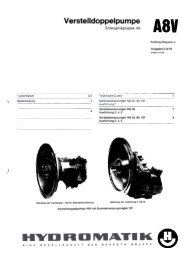
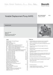
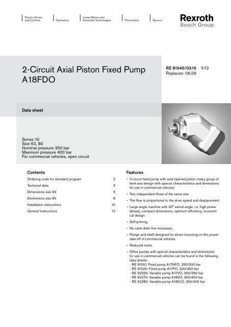
Electric Drivesand ControlsHydraulicsLinear Motion andAssembly TechnologiesPneumaticsService2-<strong>Circuit</strong> <strong>Axial</strong> <strong>Piston</strong> <strong>Fixed</strong> <strong>Pump</strong><strong>A18FDO</strong>RE 91540/03.10 1/12Replaces: 06.09Data sheetSeries 10Size 63, 80Nominal pressure 350 barMaximum pressure 400 barFor commercial vehicles, open circuitContentsOrdering code for standard program 2Technical data 3Dimensions size 63 6Dimensions size 80 8Installation instructions 10General instructions 12Features––2-circuit fixed pump with axial tapered piston rotary group ofbent axis design with special characteristics and dimensionsfor use in commercial vehicles.––Two independent flows of the same size––The flow is proportional to the drive speed and displacement.––Large-angle machine with 40° swivel angle, i.e. high powerdensity, compact dimensions, optimum efficiency, economicaldesign––Self-priming––No case drain line necessary––Flange and shaft designed for direct mounting on the powertake-off of commercial vehicles––Reduced noise––Other pumps with special characteristics and dimensionsfor use in commercial vehicles can be found in the followingdata sheets:- RE 91510: <strong>Fixed</strong> pump A17NFO, 250/300 bar- RE 91520: <strong>Fixed</strong> pump A17FO, 300/350 bar- RE 92260: Variable pump A17VO, 300/350 bar- RE 92270: Variable pump A18VO, 350/400 bar- RE 92280: Variable pump A18VLO, 350/400 bar
2/12 Bosch Rexroth AG <strong>A18FDO</strong> Series 10 | RE 91540/03.10Ordering code for standard programA18F DO / 10 M W K0 E8 1 –01 02 03 04 05 06 07 08 09 10 11<strong>Axial</strong> piston unit01 Bent axis design, fixed, nominal pressure 350 bar, maximum pressure 400 bar, for commercial vehicles (truck) A18FOperation mode02 2-circuit pump, open circuit DOSize (NG)03 Theoretical displacement (per circuit) see table of values on page 5 063 080Series04 Series 1, index 0 10Version of port and fixing threads05 Metric M06Direction of rotationViewed from drive shaft clockwise RSealscounter-clockwise07 FKM (fluor-caoutchouc) including the 2 shaft seal rings in FKM WMounting flange08 Special flange ISO 7653-1985 (for trucks) K0Drive shaft09 Splined shaft similar to DIN ISO 14 (for trucks) E8Service line ports10 Threaded port A 1 and A 2 at rear, SAE flange port S at rear 111Standard / special versionStandard version 0Special versionNoteShort designation X refers to a special version not covered by the ordering code.LS
RE 91540/03.10 | <strong>A18FDO</strong> Series 10 Bosch Rexroth AG 3/12Technical dataHydraulic fluidBefore starting project planning, please refer to our datasheets RE 90220 (mineral oil) and RE 90221 (environmentallyacceptable hydraulic fluids) for detailed information regardingthe choice of hydraulic fluid and application conditions.If environmentally acceptable hydraulic fluids are being used,the limitations regarding technical data and seals mentioned inRE 90221 must be observed.When ordering, indicate the hydraulic fluid that is to be used.NoteThe fixed pump <strong>A18FDO</strong> is not suitable for operation withwater-containing HF hydraulic fluid.Selection diagramViscosity ν [mm 2 /s]-40°1600 -20° 0° 20° 40° 60° 80° 100°1600100060040020010060402010VG 22VG 32VG 46VG 68VG 10055-40° -25° -10° 0° 10° 30° 50° 70° 90° 115°Temperature t [°C]t min = -40 °C Hydraulic fluid temperature range t max = +115 °C3616 optDetails regarding the choice of hydraulic fluidThe correct choice of hydraulic fluid requires knowledge of theoperating temperature in relation to the ambient temperature: inan open circuit the tank temperature.The hydraulic fluid should be chosen so that the operating viscosityin the operating temperature range is within the optimumrange (ν opt ), see shaded area of the selection diagram. Werecommended that the higher viscosity class be selected ineach case.Example: At an ambient temperature of X °C, an operating temperatureof 60 °C is set in the circuit. In the optimum operatingviscosity range (ν opt. shaded area), this corresponds to theviscosity classes VG 46 or VG 68; to be selected: VG 68.NoteThe case drain temperature, which is affected by pressure andspeed, is always higher than the tank temperature. At no pointof the component may the temperature be higher than 115 °C,however. The temperature difference specified below is to betaken into account when determining the viscosity in the bearing.If the above conditions cannot be maintained due to extremeoperating parameters, please contact us.Filtration of the hydraulic fluidFiltration improves the cleanliness level of the hydraulic fluid,which, in turn, increases the service life of the axial piston unit.To ensure the functional reliability of the axial piston unit, agravimetric evaluation is necessary for the hydraulic fluid todetermine the amount of contamination by solid matter andto determine the cleanliness level according to ISO 4406. Acleanliness level of at least 20/18/15 is to be maintained.At very high hydraulic fluid temperatures (90 °C to maximum115 °C), a cleanliness level of at least 19/17/14 according toISO 4406 is necessary.If the above classes cannot be achieved, please contact us.Viscosity and temperatureViscosity [mm 2 /s] Temperature CommentTransport and storage T min ≥ -50 °CT opt = +5 °C to +20 °Cup to 12 months with standard factory preservationup to 24 months with long-term factory preservation(Cold) start-up n max = 1600 T St ≥ -40 °C t ≤ 3 min, without load (p ≤ 50 bar), n ≤ 1000 rpmPermissible temperatureDT ≤ 25 Kbetween axial piston unit and hydraulic fluiddifferenceWarm-up phase n < 1600 to 400 T = -40 °C to -25 °C at p nom , 0.5 • n nom and t ≤ 15 minOperating phaseTemperature difference DT = approx. 12 K The temperature of the hydraulic fluid in the bearingis (depending on pressure and speed) approx. 12 Khigher than that of the case drain fluid at port R.Continuous operation n = 400 to 10 T = -25 °C to +90 °C no restriction within the permissible datan opt = 16 to 36Short-term operation n min = < 10 to 5 T max = +115 °C t < 3 min, p < 0.3 • p nomShaft seal ring FKM T ≤ +115 °C see page 4
4/12 Bosch Rexroth AG <strong>A18FDO</strong> Series 10 | RE 91540/03.10Technical dataOperating pressure rangePressure at service line port A 1 and A 2Nominal pressure p nom __________________ 350 bar absoluteMaximum pressure p max _ _______________ 400 bar absoluteSingle operating period ______________________________ 5 sTotal operating period ______________________________ 50 hMinimum pressure (high-pressure side) ___________ 10 barRate of pressure change R A max _______________ 9000 bar/sPressure pp nomDpDtDefinitionNominal pressure p nomThe nominal pressure corresponds to the maximum designpressure.Maximum pressure p maxThe maximum pressure corresponds to the maximum operatingpressure within the single operating period. The sum of thesingle operating periods must not exceed the total operatingperiod.Minimum pressure (high-pressure side)Minimum pressure on the high-pressure side (A 1 and A 2 ) that isrequired in order to prevent damage to the axial piston unit.Rate of pressure change R AMaximum permissible rate of pressure build-up and pressurereduction during a pressure change over the entire pressurerange.Time tPressure at suction port S (inlet)Minimum suction pressure p S min ___________ 0.8 bar absoluteMaximum suction pressure p S max ____________ 2 bar absoluteMinimum pressure (inlet)In order to avoid damage to the axial piston unit, a minimumpressure must be ensured at the suction port S (inlet). Theminimum pressure is dependent on the speed of the axialpiston unit.Inlet pressure pabs [bar]21.510.50.91.0 1.1 1.2 1.3 1.4 1.5Speednn maxPlease contact us if these conditions cannot be satisfied.Pressure pSingle operating periodMaximum pressure p maxNominal pressure p nomt 1t 2t nMinimum pressure (high-pressure side)Total operating period = t 1 + t 2 + ... + t nCase drain fluidTime tThe case drain chamber is connected to the suction chamber.A case drain line from the case to the tank is not required (port"R" is plugged)Shaft seal ringThe FKM shaft seal ring is permissible for case drain temperaturesfrom -25 °C to +115 °C.NoteFor the temperature range below -25 °C, the values in the tableon page 3 are to be observed.
RE 91540/03.10 | <strong>A18FDO</strong> Series 10 Bosch Rexroth AG 5/12Technical dataTable of values (theoretical values, without efficiencies and tolerances; values rounded)Size NG 63 80Displacement V g cm 3 2 x 63 2 x 80Speed maximum 1) at V g n nom rpm 1700 1500Speed maximum 2) n max rpm 2450 2150Flow at n nom and V g q v max l/min 2 x 10⁷ 2 x 120Power at n nom , V g and Δp = 350 bar P max kW 125 140Torque at V g and Δp = 350 bar T Nm 702 891Mass moment T G Nm 30 40Rotary stiffness c Nm/rad 12000 15000Moment of inertia for rotary group J GR kgm 2 0.0093 0.0134Maximum angular acceleration α rad/s² 3800 3000Filling capacity V L 1.2 1.7Mass (approx.) m kg 20.9 24.81) The values shown are valid for an absolute pressure pabs= 1 bar at suction port "S" and for operation with mineral fluid with aspecific mass of 0.88kg/l.2) Maximum speed (limiting speed) with increased inlet pressure pabs at suction port S (see diagram on page 4)NoteOperation above the maximum values or below the minimum values may result in a loss of function, a reduced service life or in thedestruction of the axial piston unit. Other permissible limit values with respect to speed variation, reduced angular acceleration asa function of the frequency and the permissible startup angular acceleration (lower than the maximum angular acceleration) can befound in data sheet RE 90261.Determining the sizeFlow q v =V g • n • η v1000[l/min]V g = Displacement per revolution in cm 3Δp = Differential pressure in barTorque T =V g • Δ p20 • π • η mh[Nm]nη v= Speed in rpm= Volumetric efficiencyPower P =2 π • T • n=q v • Δp60000 600 • η t[kW]η mh = Mechanical-hydraulic efficiencyη t = Total efficiency (η t = η v • η mh )Permissible axial loading of the drive shaftThe values given are maximum values and do not apply to continuous operation. For drives with radial loading(pinion, V-belt drives), please contact us!Size NG 63 80When standstill or when axial piston unitoperation in non-pressurized conditionsPermissible axial forceper bar operating pressureNoteForce-transfer direction of the permissible axial force+ F ax max = Increase in service life of bearings− F ax max = Reduction in service life of bearings (avoid)<strong>Circuit</strong> diagramRA 2A 1± F ax max N 0 0+F ax+ F ax per N/bar 53 60– − F ax per N/bar 0 0S
6/12 Bosch Rexroth AG <strong>A18FDO</strong> Series 10 | RE 91540/03.10Dimensions size 63Before finalizing your design, request a bindinginstallation drawing. Dimensions in mm.ø80 -0.03 -0.06915.4286.4271.6253.6235.6R144 1)40°7953 1)A 2103.3124.7146.2169.814510796801)132[waist (Taillenmaß) dimension]Center of gravity1380109A 1XView Xfor counter-clockwiserotationA 2View Xfor clockwise rotation69.5 7843 30A 2S158.456S77.8A 1A 142.9
RE 91540/03.10 | <strong>A18FDO</strong> Series 10 Bosch Rexroth AG 7/12Dimensions size 63Drive shaftE8 Splined shaft similar DIN ISO 148x32x35Before finalizing your design, request a bindinginstallation drawing. Dimensions in mm.1) 2)ø34.9 -0.1M12 x 1.75ø8.19.52836.8ø38.4ø42Groove forretaining ring35 x 1.5 DIN 47126.15512PortsDesignation Port for Standard Size 2) Maximum Statepressure[bar] 3)A 1 , A 2 Service line DIN ISO 228 G3/4; 16 deep 400 OSSuctionSAE J518 2 in2 OFixing threadsDIN 13 M12 x 1.75; 20 deepR Air bleed DIN 3852 5) M18 x 1.5; 12 deep 2 X 4)Center bore according to DIN 332 (thread according to DIN 13)Observe the general instructions on page 12 for the maximum tightening torques.Short-term pressure spikes may occur depending on the application. Keep this in mind when selecting measuring devices andfittings.Only open port R for filling and air bleed1)2)3)4)5)The spot face can be deeper than specified in the appropriate standard.O = Must be connected (plugged on delivery)X = Plugged (in normal operation)
8/12 Bosch Rexroth AG <strong>A18FDO</strong> Series 10 | RE 91540/03.10Dimensions size 80Before finalizing your design, request a bindinginstallation drawing. Dimensions in mm.ø80 -0.03-0.06915.4303.6286.8266.3245.7R166 1)40°8453 1)106.6131.1155.6181.615510796801)142[waist (Taillenmaß) dimension]Center of gravity1380109XView Xfor counter-clockwiserotationA 2A 2SA 1A 2SView Xfor clockwise rotation74.5503086172.66488.9A 1A 150.8
RE 91540/03.10 | <strong>A18FDO</strong> Series 10 Bosch Rexroth AG 9/12Dimensions size 80Drive shaftE8 Splined shaft similar DIN ISO 148x32x351) 2)ø34.9 -0.1M12 x 1.75ø8.19.52836.8ø38.4ø42Before finalizing your design, request a bindinginstallation drawing. Dimensions in mm.Groove forretaining ring35 x 1.5 DIN 47126.15512PortsDesignation Port for Standard Size 2) Maximum Statepressure[bar] 3)A 1 , A 2 Service line DIN ISO 228 G1; 18 deep 400 OSSuctionSAE J518 2 1/2 in2 OFixing threadsDIN 13 M12 x 1.75; 17 deepR Air bleed DIN 3852 5) M18 x 1.5; 12 deep 2 X 4)Center bore according to DIN 332 (thread according to DIN 13)Observe the general instructions on page 12 for the maximum tightening torques.Short-term pressure spikes may occur depending on the application. Keep this in mind when selecting measuring devices andfittings.Only open port R for filling and air bleed1)2)3)4)5)The spot face can be deeper than specified in the appropriate standard.O = Must be connected (plugged on delivery)X = Plugged (in normal operation)
10/12 Bosch Rexroth AG <strong>A18FDO</strong> Series 10 | RE 91540/03.10Installation instructionsGeneralDuring commissioning and operation, the axial piston unit mustbe filled with hydraulic fluid and air bled. This is also to be observedfollowing a relatively long standstill as the system mayempty via the hydraulic lines.The case drain chamber is internally connected to the suctionchamber. A case drain line from the case to the tank is notrequired.To achieve favorable noise values, decouple all connectinglines using elastic elements and avoid above-tank installation.In all operational states, the suction line must flow into the tankbelow the minimum fluid level. The permissible suction heighth S results from the overall loss of pressure, it must not, however,be higher than h S max = 800 mm. The minimum suctionpressure at port S must also not fall below 0.8 bar absoluteduring operation and during cold start.Installation positionSee the following examples 1 to 4.Additional installation positions are available upon request.Recommended installation position: 1 and 2.Below-tank installation (standard)Below-tank installation is when the axial piston unit is installedoutside of the tank below the minimum fluid level.1 2Rh t minh minh t minh minSAbove-tank installationAbove-tank installation is when the axial piston unit is installedabove the minimum fluid level of the tank.Observe the maximum permissible suction height h S max = 800 mm.3 4RInstallationpositionLSh S maxh t minh minAir bleedh S maxh t minh min3 R L4 S SLRSh t minh minh S maxFilling / air bleedAir bleed portSuction portSFillingMinimum permissible immersion depth (200 mm)Minimum permissible spacing from suction port totank base (100 mm)Maximum permissible suction height (800 mm)RSRInstallationpositionAir bleedFilling1 R S2 – S
RE 91540/03.10 | <strong>A18FDO</strong> Series 10 Bosch Rexroth AG 11/12Notes
12/12 Bosch Rexroth AG <strong>A18FDO</strong> Series 10 | RE 91540/03.10General instructions––The <strong>A18FDO</strong> pump is designed to be used in open circuits.––Project planning, assembly and commissioning of the axial piston unit require the involvement of qualified personnel.––Before using the axial piston unit, please read the corresponding operating instructions completely and thoroughly. If necessary,these can be requested from Rexroth.––The service line ports and function ports are only designed to accommodate hydraulic lines.––During and shortly after operation, there is a risk of burns on the axial piston unit. Take appropriate safety measures(e.g. by wearing protective clothing).––Depending on the operational state of the axial piston unit (operating pressure, fluid temperature), the characteristic may shift.––Pressure ports:The ports and fixing threads are designed for the specified maximum pressure. The machine or system manufacturer mustensure that the connecting elements and lines correspond to the specified operating conditions (pressure, flow, hydraulic fluid,temperature) with the necessary safety factors.––The data and notes contained herein must be adhered to.––The following tightening torques apply:--Threaded hole of the axial piston unit:The maximum permissible tightening torques M G max are maximum values of the threaded holes and must not be exceeded.For values, see the following table.--Fittings:Observe the manufacturer's instruction regarding the tightening torques of the used fittings.--Fixing screws:For fixing screws according to DIN 13, we recommend checking the tightening torque individually according to VDI 2230.--Locking screws:For the metallic locking screws supplied with the axial piston unit, the required tightening torques of locking screws M V apply.For values, see the following table.––The product is not approved as a component for the safety concept of a general machine according to DIN EN ISO 13849.PortsMaximum permissible Required tightening torqueWAF hexagon socket oftightening torque of the of the locking screws M Vthe locking screwsStandard Threaded size threaded holes M G maxDIN 3852 M18 x 1.5 66 Nm 60 Nm 8 mmDIN ISO 228 G3/4 330 Nm − −G1 480 Nm − −Accessories for <strong>A18FDO</strong>The following accessories are available from Rexroth for the <strong>A18FDO</strong>:––Coupling flange, for pumps driven via a cardan shaft (see RE 95001)––Suction studs, in all variations (see RE 95004)Bosch Rexroth AGHydraulics<strong>Axial</strong> piston unitsGlockeraustraße 289275 Elchingen, GermanyPhone +49 (0) 73 08 82-0Fax +49 (0) 73 08 72 74info.brm-ak@boschrexroth.dewww.boschrexroth.com/axial-piston-pumps© This document, as well as the data, specifications and other information setforth in it, are the exclusive property of Bosch Rexroth AG. It may not be reproducedor given to third parties without its consent.The data specified above only serve to describe the product. No statementsconcerning a certain condition or suitability for a certain application can be derivedfrom our information. The information given does not release the user fromthe obligation of own judgment and verification. It must be remembered that ourproducts are subject to a natural process of wear and aging.Subject to change.