RS232/485/LAN Serial Communication Control ... - Mitsubishi Electric
RS232/485/LAN Serial Communication Control ... - Mitsubishi Electric
RS232/485/LAN Serial Communication Control ... - Mitsubishi Electric

Create successful ePaper yourself
Turn your PDF publications into a flip-book with our unique Google optimized e-Paper software.
<strong>RS232</strong>/<strong>485</strong>/<strong>LAN</strong> <strong>Serial</strong> <strong>Communication</strong> <strong>Control</strong>for MDT652S1. ApplicationThis document defines the communication protocols for serial control of the MDT652S.-----Revision History-----1 st Release May. 24 2011. H.Tanizoe, M.Juichiya, T.Kimura, Y.Ashizaki(1/56)
4. <strong>Communication</strong> Format4-1.Basic commandThis command set supports only the basic control of monitor and does NOT support multi monitor controlby daisy chained connection. This command set will be written in the user’s manual of MDT652S.1) <strong>Control</strong> command diagramThe command is structured by the address code, function code, data code and end code. The length of the command is different foreach function.2) <strong>Control</strong> sequence(1) The command from a computer to the LCD monitor will be sent in 600ms.(2) The LCD monitor will send a return command 600ms* after it has received and encoded. If the command isn’treceived correctly, the LCD monitor will not send the return command.(3) The personal computer checks the command and confirms if the command, which has been sent, has been executed or not.(4) This LCD monitor sends various codes other than return code. When having a control sequence by RS-232C, reject othercodes from personal computers side.*: The sending time of return command may delay depending on the condition (during changing of the input signal, etc.).Example: Turn the power ON ( ’ ’ is for ASCII code)Note: The replied status is for communication confirmation. When you want to know the display condition, please use the ‘Readcommand’. (See page 6)(5/56)
3) Operation commandsThe operation commands execute the basic operation setting of this LCD monitor.It may not operate when changing the signal:Operation ASCII HEXPOWER ON ! 21hPOWER OFF " 22hINPUT HDMI _r1 5Fh 72h 31hINPUT DVI-D _r2 5Fh 72h 32hINPUT D-SUB _r3 5Fh 72h 33hINPUT BNC _r4 5Fh 72h 34hINPUT CAT5 _r5 5Fh 72h 35hINPUT DisplayPort _r6 5Fh 72h 36hINPUT VIDEO _v1 5Fh 76h 31hINPUT YPbPr _v2 5Fh 76h 32hINPUT S-VIDEO* _v3 5Fh 76h 33h* S-VIDEO is SEPARATE only4) Read commandHost computer sends the command without Data-code to monitor.After receiving this command, the monitor returns the command with Data-code of current status to host computer.< ex. > When Host computer ask Power status of monitor, the status of monitor is powered-on.Structure of the Read-commandPOWERInputPicture modeTemperatureof InternalmonitorASCIIHEXFunction Data (Receive) Function Data (Receive)ON vP 1 76 50 31OFF(sleep/stand by) vP 0 76 50 30HDMI vI r1 76 49 72 31DVI-D vI r2 76 49 72 32D-SUB vI r3 76 49 72 33BNC vI r4 76 49 72 34CAT5 vI r5 76 49 72 35DisplayPort vI r6 76 49 72 36Video vI v1 76 49 76 31YPbPr vI v2 76 49 76 32S-VIDEO vI v3 76 49 76 33HIGHBRIGHT vM p1 76 4D 70 31STANDARD vM p2 76 4D 70 32AroundMainboardAroundPowerPCBresolution1˚C tc1 (ex.) +25 74 63 31 2B 20 32 35resolution1˚C tc2 (ex.) +31 74 63 32 2B 20 33 31(6/56)
5) Remote command(Not executable in sleep/stand-by mode. When the remote commands are sent while sleep/stand-by mode, the stand-by mode isonly canceled.)Some remote control operations can be achieved by the remote command codes. The remote commands have no data codes.Button’s name on remoteFunctionCharacterASCII+/VOLUME r06 72h 30h 36h-/VOLUME r07 72h 30h 37hAV MUTE ra6 72h 61h 36hAUTO SETUP r09 72h 30h 39h[Example] When executing the AUTOSETUP. (Figures and symbols enclosed in quotation marks are ASCII codes.):Sending commandsfrom the PC, etc.‘30’ ‘30’ ‘72’ ‘30’ ‘39’ ‘0D’00r09Status codefrom the projectorDescriptionCommand operating the sameas the MENU button‘30’ ‘30’ ‘72’ ‘30’ ‘39’ ‘0D’00r09Command receipt confirmation(Command echo back)(7/56)
4-2.Extended commandNote: This command set supports multi monitor control by daisy chained connection. This commandset will NOT be written in the user’s manual of MDT652S.The command packet consists of four parts, Header, Message, Check code and Delimiter.Header Message Check Code DelimiterSequence of a typical procedure to control a monitor is as follows,[A controller and a monitor, two-way communication composition figure]<strong>Control</strong>lerMonitorDelimiterDelimiterDelimiterDelimiterGet ParameterCheck Code Message HeaderGet Parameter ReplyHeader Message Check Code DelimiterSet ParameterCheck Code Message HeaderSet Parameter ReplyHeader Message Check Code DelimiterGet ParameterCheck Code Message HeaderGet Parameter ReplyHeader Message Check Code DelimiterSave Current Setting CommandCheck Code Message HeaderThe controller sends a command toget a value from the monitor thatyou want to change.The monitor replies with thecurrent value of the requesteditem.The controller sends commands toset an adjusted value.The monitor replies to thecontroller for confirmation.The controller sends a command toget a value for confirmation.The monitor replies with anadjusted value.The controller requests to storethe adjusted value to the monitor.(8/56)
4.1 Header block format (fixed length)Header Message Check code DelimiterReserved DestinationMessage MessageSOHSource'0''A'TypeLength1 st 2 nd 3 rd 4 th 5 th 6 th -7 th1 st byte) SOH: Start of HeaderASCII SOH (01h)2 nd byte) Reserved: Reserved for future extensions.MDT652S must be ASCII '0'(30h)3 rd byte) Destination: Destination equipment ID. (Receiver)Specify a command’s receiver’s address.If the command should be sent to certain monitor only, the either of character ‘A’(41h) to ‘Z’(5Ah)which is corresponding to monitor ID from No1 to No.26 should be set to this portion. If itis a broad cast command(only “set command” is available), then the ’*’(2Ah)should be applied.4 th byte) Source: Source equipment ID. (Sender)Specify a sender address.The controller must be ‘0’(30h).5 th byte) Message Type: (Case sensitive.)Refer to section 4.2 “Message block format” for more details.ASCII 'A' (41h): CommandASCII 'B' (42h): Command reply.ASCII 'C' (43h): Get current parameter from a monitor.ASCII 'D' (44h): "Get parameter" reply.ASCII 'E' (45h): Set parameter.ASCII 'F' (46h): "Set parameter" reply.6 th -7 th bytes) Message Length:Specify the length of the message (that follows the header) from STX to ETX.This length includes STX and ETX.The byte data must be encoded to ASCII characters.Ex.) The byte data 3Ah must be encoded to ASCII characters '3' and 'A' (33h and 41h).The byte data 0Bh must be encoded to ASCII characters '0' and 'B' (30h and 42h).(9/56)
4.2 Message block formatHeader Message Check code Delimiter“Message block format” is allied to the “Message Type” in the “Header”.Refer to the section 6 “Message format” for more detail.1)Get current parameterThe controller sends this message when you want to get the status of the monitor.For the status that you want to get, specify the “OP code page” and “OP code”,refer to “Appendix A. Operation code table”.“Message format” of the “Get current parameter” is as follows;STXOP code page OP codeHi Lo Hi LoETX‣ Refer to section 5.1 “Get current parameter from a monitor.” for more details.2)Get Parameter replyThe monitor will reply with the status of the requested item specified by the controllerin the “Get parameter message”.“Message format” of the “Get parameter reply” is as follows;Result OP code page OP code Type Max value Current ValueSTXHi Lo Hi Lo Hi Lo Hi Lo MSB LSB MSB LSB‣ Refer to section 5.2 “Get parameter reply” for more details.ETX3)Set parameterThe controller sends this message to change a setting of the monitor.Message format of the “Set parameter” is as follows;STXOP code page OP code Set ValueHi Lo Hi Lo MSB LSBETX‣ Refer to section 5.3 “Set parameter” for more details.STX4)Set Parameter replyThe monitor replies with this message for a confirmation of the “Set parameter message”.Message format of the “Set parameter reply” is as follows;Requested settingResult OP code page OP code Type Max valueValueHi Lo Hi Lo Hi Lo Hi Lo MSB LSB MSB LSB‣ Refer to section 5.4 “Set parameter reply” for more details.ETX5)Command“Command message” format depends on each command.Usually, this “command message” is used for some non-slider controls and some special operations,such as “Save current settings”, “Get timing report”, “power control”, “Schedule”, etc. Refer tosection 5.5 “Commands message” for more details.(10/56)
6)Command replyThe monitor replies to a query from the controller.“Command reply message” format depends on each command.Refer to section 5.5 “Commands message” for more details.(11/56)
4.5 Check codeHeader Message Check code DelimiterCheck code is the Block Check Code (BCC) between the Header and the End of Message except SOH.2 7 2 6 2 5 2 4 2 3 2 2 2 1 2 0SOH D 0Reserved D 1Destination D 2Source D 3Type D 4Length D 5STX D 6Data D 7| || |ETXD nCheck code D n+1 P P P P P P P PD n+1 = D 1 XOR D 2 XOR D 3 XOR ,,, D nXOR: Exclusive ORFollowing is an example of a Check code (BCC) calculation.SOHReservedDestinationAddressHeaderSourceAddressMessagetypeMessage lengthSTXOP codepageMessageOP code Set Value ETXCheckcode(BCC)Delimiter01 30 41 30 45 30 41 02 30 30 31 30 30 30 36 34 03 77 0DD 0 D 1 D 2 D 3 D 4 D 5 D 6 D 7 D 8 D 9 D 10 D 11 D 12 D 13 D 14 D 15 D 16 D 17 D 18Check code (BCC) D 17 = D 1 xor D 2 xor D 3 xor … xor D 14 xor D 15 xor D 16= 30h xor 41h xor 30h xor 45h xor 30h xor 41hxor 02h xor 30h xor 30h xor 31h xor 30h xor 30hxor 30h xor 36h xor 34h xor 03h= 77h4.6 DelimiterPacket delimiter code; ASCII CR(0Dh).Header Message Check code Delimiter(12/56)
5. Message type5.1 Get current Parameter from a monitor.OP code page OP codeSTXETXHi Lo Hi Lo1 st 2 nd -3 rd 4 th –5 th 6 thSend this message when you want to get the status of a monitor.For the status that you want to get, specify the “OP code page” the “OP code”, refer to “AppendixA. Operation code table”.1 st byte) STX: Start of MessageASCII STX (02h)2 nd -3 rd bytes) OP code page: Operation code page.Specify the “OP code page” for the control which you want to get the status.Refer to “Appendix A Operation code table” for each item.OP code page data must be encoded to ASCII characters.Ex.) The byte data 02h must be encoded to ASCII characters '0' and '2' (30h and 32h).OP code page 02h -> OP code page (Hi) = ASCII '0' (30h)OP code page (Lo) = ASCII '2' (32h)Refer to Operation code table. (Appendix A)4 th –5 th bytes) OP code: Operation codeRefer to “Appendix A Operation code table” for each item.OP code data must be encoded to ASCII characters.Ex.) The byte data 3Ah must be encoded to ASCII characters '3' and 'A' (33h and 41h).OP code 3Ah ->OP code (Hi) = ASCII '3' (33h)OP code (Lo) = ASCII 'A' (41h)Refer to Operation code table.6 th byte) ETX: End of MessageASCII ETX (03h)5.2 "Get parameter" replySTXResult OP code page OP code Type Max value Current ValueHi Lo Hi Lo Hi Lo Hi Lo MSB LSB MSB LSBETX1 st 2 nd -3 rd 4 th –5 th 6 th –7 th 8 th -9 th 10 th -13 th 14 th -17 th 18 thMDT652S replies with a current value and the status of the requested item (operation code).1 st byte) STX: Start of MessageASCII STX (02h)2 nd -3 rd bytes) Result code.These bytes indicate a result of the requested commands as follows,(13/56)
00h: No Error.01h: Unsupported operation with this monitor or unsupported operation under current condition.This result code from the monitor is encoded to ASCII characters.Ex.) The byte data 01h is encoded to ASCII character '0' and '1' (30h and 31h).4 th –5 th bytes) OP code page: Operation code page.These bytes indicate a replying item's OP code page.This returned value from the monitor is encoded to ASCII characters.Ex.) The byte data 02h is encoded to ASCII character '0' and '2' (30h and 32h).Refer to the operation codes table.6 th –7 th bytes) OP code: Operation codeThese bytes indicate a replying item's OP code.This returned value from the monitor is encoded to ASCII characters.Refer to the operation code table.Ex.) The byte data 1Ah is encoded to ASCII character '1' and 'A' (31h and 41h).8 th -9 th bytes) Type: Operation type codeThis returned value from the monitor is encoded to ASCII characters.Ex.) The byte data 01h is encoded to ASCII character '0' and '1' (30h and 31h).00h: Set parameter01h: MomentaryLike the AutoSetup function which automatically changes the parameter.10 th -13 th bytes) Max. value: Maximum value which monitor can accept. (16bits)This returned value from the monitor is encoded to ASCII characters.Ex.) '0','1','2' and '3' means 0123h (291)14 th -17 th bytes) Current Value: (16bits)This returned value from the monitor is encoded to ASCII characters.Ex.) '0','1','2' and '3' means 0123h (291)18 th byte) ETX: End of MessageASCII ETX (03h)5.3 Set parameterOP code page OP code Set ValueSTXETXHi Lo Hi Lo MSB LSB1 st 2 nd -3 rd 4 th -5 th 6 th -9 th 10 thSend this message to change monitor’s adjustment and so on.The controller requests a monitor to change value.1 st byte) STX: Start of MessageASCII STX (02h)2 nd -3 rd bytes) OP code page: Operation code page(14/56)
This OP code page data must be encoded to ASCII characters.Ex) The byte data 02h must be encoded to ASCII '0' and '2' (30h and 32h).Refer to the Operation code table.4 th -5 th bytes) OP code: Operation codeThis OP code data must be encoded to ASCII characters.OP code 1Ah ->OP code (Hi) = ASCII '1' (31h)OP code (Lo) = ASCII 'A' (41h)Refer to the Operation code table.6 th -9 th bytes) Set value: (16bit)This data must be encoded to ASCII characters.Ex.) 0123h -> 1 st (MSB) = ASCII '0' (30h)2 nd = ASCII '1' (31h)3 rd = ASCII '2' (32h)4 th (LSB) = ASCII '3' (33h)10 th byte) ETX: End of MessageASCII ETX (03h)5.4 "Set parameter" replyRequested settingResult OP code page OP code Type Max valueSTXValueETXHi Lo Hi Lo Hi Lo Hi Lo MSB LSB MSB LSB1 st 2 nd -3 rd 4 th -5 th 6 th -7 th 8 th -9 th 10 th -13 th 14 th -17 th 18 thThe Monitor echoes back the parameter and status of the requested operation code.(If command is sent as “Broadcast” then no reply should be sent back.)1 st byte) STX: Start of MessageASCII STX (02h)2 nd -3 rd bytes) Result codeASCII '0''0' (30h, 30h): No ErrorASCII '0''1' (30h, 31h): Unsupported operation with this monitor or unsupported operation undercurrent condition.4 th -5 th bytes) OP code page: Echoes back the Operation code page for confirmation.Reply data from the monitor is encoded to ASCII characters.Ex.) OP code page 02h -> OP code page = ASCII '0' and '2' (30h and 32h)Refer to Operation code table.6 th -7 th bytes) OP code: Echoes back the Operation code for confirmation.Reply data from the monitor is encoded to ASCII characters.Ex.) OP code 1Ah ->OP code (Hi) = ASCII '1' (31h)Refer to Operation code tableOP code (Lo) = ASCII 'A' (41h)(15/56)
8 th -9 th bytes) Type: Operation type codeASCII '0''0' (30h, 30h): Set parameterASCII '0''1' (30h, 31h): MomentaryLike Auto Setup function, that automatically changes the parameter.10 th -13 th bytes) Max. value: Maximum value that monitor can accept. (16bits)Reply data from the monitor is encoded to ASCII characters.Ex.) '0''1''2''3' means 0123h (291)14 th -17 th bytes) Requested setting Value: Echoes back the parameter for confirmation. (16bits)Reply data from the monitor is encoded to ASCII characters.Ex.) '0''1''2''3' means 0123h (291)18 th byte) ETX: End of MessageASCII ETX (03h)5.5 Commands"Command message format" depends on each command. Some commands are shown with usage. Refer tosection 7 to 10.5.5.1 Save Current Settings.The controller requests for the monitor to store the adjusted value.STXCommand code'0' 'C'ETX‣ Send "OC"(30h, 43h) as Save current settings command.‣ Complete "Save Current setting" command packet as follows;(The destination “A” (monitor ID of 1) is only an example. It should be changed accordingto the target monitor ID)ASCII: 01h-30h-41h-30h-41h-30h-34h-02h-30h-43h-03h-CHK-0DhSOH-'0'-'A'-'0'-'A'-'0'-'4'-STX-'0'-'C'-ETX-CHK- CRThe monitor replies the packet for confirmation as follows;SOH-'0'-'0'-'A'-'B'-'0'-'6'-STX-'0'-'0'-'0'-'C'-ETX-CHK- CR5.5.1a Save Current Settings Quick.The controller requests for the monitor to store the adjusted value.This command supports only following items, in order to shorten execute time in monitor inside.CONTRAST, BRIGHT, Color Temperature, IR <strong>Control</strong>, Inoformation OSD, H-Position, V-Position, Sharpness,Black Level, Tint, Color, OSD Turn Off, Off Timer, OSD H-Position, OSD V-Position, Power On Delay,Gamma Selection, Tiling, Monitor ID, Clock, Clock Phase, Zoom, H-Resolution, V-Resolution.STXCommand code'0' 'D'ETX(16/56)
‣ Send "OD"(30h, 44h) as Save current settings quick command.‣ Complete "Save Current setting" command packet as follows;ASCII: 01h-30h-41h-30h-41h-30h-34h-02h-30h-44h-03h-CHK-0DhSOH-'0'-'A'-'0'-'A'-'0'-'4'-STX-'0'-'D'-ETX-CHK- CRThe monitor replies the packet for confirmation as follows;SOH-'0'-'0'-'A'-'B'-'0'-'6'-STX-'0'-'0'-'0'-'D'-ETX-CHK- CR5.5.2 Get Timing Report and Timing reply.The controller requests the monitor to report the displayed image timing.STXCommand code'0' '7'ETX‣ Send "07"(30h, 37h) as Get Timing Report command.‣ Complete "Get Timing Report" command packet as follows;(The destination “A” (monitor ID of 1) is only an example. It should be changed accordingto the target monitor ID)ASCII: 01h-30h-41h-30h-41h-30h-34h-02h-30h-37h-03h-CHK-0DhSOH-'0'-'A'-'0'-'A'-'0'-'4'-STX-'0'-'7'-ETX-CHK- CRThe monitor replies status as the following format;Command SS H Freq. V Freq.STX'4' 'E' Hi Lo MSB LSB MSB LSB‣ SS: Timing status byteBit 7 = 1: Sync Frequency is out of range.Bit 6 = 1: Unstable countBit 5-2 Reserved (Don't care)Bit 1 1:Positive Horizontal sync polarity.0:Negative Horizontal sync polarity.Bit 0 1:Positive Vertical sync polarity.0:Negative Vertical sync polarity.‣ H Freq: Horizontal Frequency in unit 0.01kHzETX‣ V Freq: Vertical Frequency in unit 0.01HzEx.) When H Freq is '1''2''A''9' (31h, 32h, 41h, 39h), it means 47.77kHz.5.5.3 NULL MessageSTXCommand code'B' 'E'ETXThe NULL message returned from the monitor is used in the following cases;‣ A timeout error has occurred. (The default timeout is 10msec for command internal gap.)‣ The monitor receives an unsupported message type.‣ The monitor detects a packet BCC (Block Check Code) error.(17/56)
‣ To tell the controller that the monitor does not have any answer to give to the host (notready or not expected)‣ Complete "NULL Message" command packet as follows;(The destination “A” (monitor ID of 1) is only an example. It should be changed accordingto the target monitor ID)01h-30h-30h-41h-41h-30h-34h—02h-42h-45h-03h-CHK-0DhSOH-'0'-'0'-'A'-'A'-'0'-'4'-STX-'B'-'E'-ETX-CHK- CR6. Typical procedure exampleThe following is a sample of procedures to control the monitor, these are examples of "Get parameter","Set parameter" and "Save current settings".6.1. How to change the “Brightness” setting.Step 1. The controller requests the Monitor to reply with the current brightness setting and capabilityto support this operation. (Get parameter)Header Message Check code DelimiterSOH-'0'-'A'-'0'-'C'-'0'-'6' STX-'0'-'0'-'1'-'0'-ETX BCC CRHeaderSOH (01h): Start Of Header'0' (30h): Reserved'A' (41h): Monitor IDIf the command should be sent to certain monitor only, the either of character ‘A’(41h) to ‘Z’(5Ah)which is corresponding to monitor ID from No1 to No.26 should be set to this portion. If it isa broad cast command(only “set command” is available), then the ’*’(2Ah)should be applied.'0' (30h): Message sender is the controller'C' (43h): Message is "Get parameter command"'0'-'6' (30h, 36h): Message length is 6 bytesMessageSTX (02h): Start of Message'0'-'0' (30h, 30h): Operation code page number is 0'1'-'0' (31h, 30h): Operation code is 10h (in the OP code page 0)ETX (03h): End of MessageCheck codeBCC: Block Check CodeRefer to the section 4.5 “Check code” for a BCC calculation.DelimiterCR (0Dh): End of packetStep 2. The monitor replies with current Brightness setting and capability to support this operation.(If command is sent as “Broadcast” then no reply should be sent back.)Header Message Check code DelimiterSOH-'0'-'0'-'A'-'D'-'1'-'2' STX-'0'-'0'-'0'-'0'-'1'-'0'-'0'-'0'BCCCR-'0'-'0'-'6'-'4'-'0'-'0'-'3'-'2'-ETXHeaderSOH (01h): Start Of Header'0' (30h): Reserved'0' (30h): Message receiver is the controller'A' (41h): Monitor IDThis portion should depend on the monitor ID of Monitor.( ’A’(41h)-‘Z’(5Ah))'D' (44h): Message Type is "Get parameter reply"'1'-'2' (31h, 32h): Message length is 18 bytes(18/56)
MessageSTX (02h): Start of Message'0'-'0' (30h, 30h): Result code. No error'0'-'0' (30h, 30h): Operation code page number is 0'1'-'0' (31h, 30h): Operation code is 10h (in the page 0)'0'-'0' (30h, 30h): This operation is "Set parameter" type'0'-'0'-'6'-'4' (30h, 30h, 36h, 34h): Brightness max value is 100(0064h)'0'-'0'-'3'-'2' (30h, 30h, 33h, 32h): Current Brightness setting is 50(0032h) as 50%ETX (03h): End of MessageCheck codeBCC: Block Check CodeRefer to the section 4.5 “Check code” for a BCC calculation.DelimiterCR (0Dh): End of packetStep 3. The controller request the monitor to change the Brightness settingHeader Message Check code DelimiterSOH-'0'-'A'-'0'-'E'-'0'-'A' STX-'0'-'0'-'1'-'0'-'0'-'0'-'5'-'0'-ETX BCC CRHeaderSOH (01h): Start Of Header'0' (30h): Reserved'A' (41h): Monitor IDIf the command should be sent to certain monitor only, the either of character ‘A’(41h) to ‘Z’(5Ah)which is corresponding to monitor ID from No1 to No.26 should be set to this portion. If it isa broad cast command(only “set command” is available), then the ’*’(2Ah)should be applied.'0' (30h): Message sender is the controller'E' (45h): Message Type is "Set parameter command"'0'-'A' (30h, 41h): Message length is 10 bytesMessageSTX (02h): Start of Message'0'-'0' (30h, 30h): Operation code page number is 0'1'-'0' (31h, 30h): Operation code is 10h (in the page 0)'0'-'0'-'5'-'0' (30h, 30h, 35h, 30h): Set Brightness setting 80(0050h) as 80%ETX (03h): End of MessageCheck codeBCC: Block Check CodeRefer to the section 4.5 “Check code” for a BCC calculation.DelimiterCR (0Dh): End of packetStep 4. The monitor replies with a message for confirmation.(If command is sent as “Broadcast” then no reply should be sent back.)Header Message Check code DelimiterSOH-'0'-'0'- 'A' -'F'-'1'-'2' STX-'0'-'0'-'0'-'0'-'1'-'0'—'0'-'0'-'0' BCCCR-'0'-'6'-'4'-'0'-'0'-'5'-'0'-ETXHeaderSOH (01h): Start Of Header'0' (30h): Reserved'0' (30h): Message receiver is the controller'A' (41h): Monitor IDThis portion should depend on the monitor ID of Monitor.( ’A’(41h)-‘Z’(5Ah))'F' (46h): Message Type is "Set parameter reply"'1'-'2' (31h, 32h): Message length is 18 bytes(19/56)
MessageSTX (02h): Start of Message'0'-'0' (30h, 30h): Result code. No error'0'-'0' (30h, 30h): Operation code page number is 0'1'-'0' (31h, 30h): Operation code is 10h (in the page 0)'0'-'0' (30h, 30h): This operation is "Set parameter" type'0'-'0'-'6'-'4' (30h, 30h, 36h, 34h): Brightness max value is 100(0064h)'0'-'0'-'5'-'0' (30h, 30h, 35h, 30h): Received a Brightness setting was 80(0050h) as 80%ETX (03h): End of MessageCheck codeBCC: Block Check CodeRefer to the section 4.5 “Check code” for a BCC calculation.DelimiterCR (0Dh): End of packet‣ Repeat Step 1 and Step 2, if you need to check the Brightness setting. (Recommended)Step 5. Request the monitor to store the Brightness setting. (Save Current Settings Command)Header Message Check code DelimiterSOH-'0'-'A'-'0'-'A'-'0'-'4' STX-'0-'C'-ETX BCC CRHeaderSOH (01h): Start Of Header'0' (30h): Reserved'A' (41h): Monitor IDIf the command should be sent to certain monitor only, the either of character ‘A’(41h) to ‘Z’(5Ah)which is corresponding to monitor ID from No1 to No.26 should be set to this portion. If it isa broad cast command(only “set command” is available), then the ’*’(2Ah)should be applied.'0' (30h): Message sender is the controller'A' (41h): Message type is "Command"'0'-'4' (30h, 34h): Message length is 4 bytesMessageSTX (02h): Start of Message'0'-'C' (30h, 43h): Command code is 0Ch as "Save current settings"ETX (03h): End of MessageCheck codeBCC: Block Check CodeRefer to the section 4.5 “Check code” for a BCC calculation.DelimiterCR (0Dh): End of packet6.2 How to read the measurement value of the built-in temperature sensors.MDT652S has two built-in temperature sensors.The controller can monitor inside temperatures by using those sensors through RS-232C.The following shows the procedure for reading the temperatures from the sensors.Step 1. Select a temperature sensor which you want to read.Header Message Check code DelimiterSOH-'0'-'A'-'0'-'E'-'0'-'A' STX-'0'-'2'-'7'-'8'-'0'-'0'-'0'-'1'-ETX BCC CRHeaderSOH (01h): Start of Header'0' (30h): Reserved'A' (41h): Monitor IDIf the command should be sent to certain monitor only, the either of character ‘A’(41h) to ‘Z’(5Ah)which is corresponding to monitor ID from No1 to No.26 should be set to this portion.'0' (30h): Message sender is the controller(20/56)
'E' (45h): Message Type is "Set parameter command"'0'-'A' (30h, 41h): Message length is 10 bytesMessageSTX (02h): Start of Message'0'-'2' (30h, 32h): Operation code page number is 02h'7'-'8' (37h, 38h): Operation code is 78h (on page 2)'0'-'0'-'0'-'1' (30h, 30h, 30h, 31h): Select the temperature sensor #1 (01h).00h: No meaning01h: Sensor #102h: Sensor #2ETX (03h): End of MessageCheck codeBCC: Block Check CodeRefer to the section 4.5 “Check code” for a BCC calculation.DelimiterCR (0Dh): End of packetStep 2. The monitor replies for confirmation.Header Message Check code DelimiterSOH-'0'-'0'-'A'-'F'-'1'-'2' STX-'0'-'0'-'0'-'2'-'7'-'8'-'0'-'0'-'0'-'0' BCCCR-'0'-'2'-'0'-'0'-'0'-'1'-ETXHeaderSOH (01h): Start of Header'0' (30h): Reserved'0' (30h): Message receiver is the controller'A' (41h): Monitor IDThis portion should depend on the monitor ID of Monitor.( ’A’(41h)-‘Z’(5Ah))'F' (46h): Message Type is "Set parameter reply"'1'-'2' (30h, 32h): Message length is 18 bytesMessageSTX (02h): Start of Message'0'-'0' (30h, 30h): Result code. No error'0'-'2' (30h, 32h): Operation code page number is 0 02h'7'-'8' (37h, 38h): Operation code is 78h (in the page 2)'0'-'0' (30h, 30h): This operation is "Set parameter" type'0'-'0'-'0'-'2' (30h, 30h, 30h, 32h): Number of temperature sensors 2 (0002h).'0'-'0'-'0'-'1' (30h, 30h, 30h, 31h): temperature sensor is #1.ETX (03h): End of MessageCheck codeBCC: Block Check CodeRefer to the section 4.5 “Check code” for a BCC calculation.DelimiterCR (0Dh): End of packetStep 3 The controller requests the monitor to send the temperature from the selected sensor.Header Message Check code DelimiterSOH-'0'-'A'-'0'-'C'-'0'-'6' STX-'0'-'2'-'7'-'9'-ETX BCC CRHeaderSOH (01h): Start of Header'0' (30h): Reserved'A' (41h): Monitor ID(21/56)
If the command should be sent to certain monitor only, the either of character ‘A’(41h) to ‘Z’(5Ah)which is corresponding to monitor ID from No1 to No.26 should be set to this portion.'0' (30h): Message sender is the controller'C' (43h): Message Type is "Get parameter "'0'-'6' (30h, 36h): Message length is 6 bytesMessageSTX (02h): Start of Message'0'-'2' (30h, 32h): Operation code page number is 02h.'7'-'9' (37h, 39h): Operation code is 79h (in the page 2)ETX (03h): End of MessageCheck codeBCC: Block Check CodeRefer to the section 4.5 “Check code” for a BCC calculation.DelimiterCR (0Dh): End of packetStep 4. The monitor replies a temperature of selected sensor.Header Message Check code DelimiterSOH-'0'-'0'-'A'-'D'-'1'-'2' STX-'0'-'0'-'0'-'2'-'7'-'9'-'0'-'0'BCCCR-'0'-'0'-'F'-'F'-'0'-'0'-'3'-'2'-ETXHeaderSOH (01h): Start of Header'0' (30h): Reserved'0' (30h): Message receiver is the controller'A' (41h): Monitor IDThis portion should depend on the monitor ID of Monitor.( ’A’(41h)-‘Z’(5Ah))'D' (44h): Message Type is "Get parameter reply"'1'-'2' (31h, 32h): Message length is 18 bytesMessageSTX (02h): Start of Message'0'-'0' (30h, 30h): Result code. No error'0'-'2' (30h, 32h): Operation code page number is 2'7'-'9' (37h, 39h): Operation code is 79h (in the page 2)'0'-'0' (30h, 30h): This operation is "Set parameter" type'0'-'0'-'F'-'F' (30h, 30h, 46h, 46h): Maximum value.'0'-'0'-'3'-'2' (30h, 30h, 33h, 32h): The temperature is 50 degrees Celsius.ETX (03h): End of MessageReadout value is 2's complement.Check codeBCC: Block Check CodeRefer to the section 4.5 “Check code” for a BCC calculation.DelimiterCR (0Dh): End of packetTemperature [Celsius]Readout valueBinaryHexadecimal+125.0 0000 0000 0111 1101 007Dh+ 25.0 0000 0000 0001 1001 0019h+ 1.0 0000 0000 0000 0001 0001h0 0000 0000 0000 0000 0000h- 1.0 1111 1111 1111 1111 FFFFh- 25.0 1111 1111 1110 0111 FFE7h- 55.0 1111 1111 1100 1001 FFC9h(22/56)
7. Power control procedure7.1 Power status read1) The controller requests the monitor to reply a current power status.Header Message Check code DelimiterSOH-'0'-'A'-'0'-'A'-'0'-'6' STX-'0'-'1'-'D'-'6'-ETX BCC CRHeaderSOH (01h): Start Of Header'0' (30h): Reserved'A' (41h): Monitor IDIf the command should be sent to certain monitor only, the either of character ‘A’(41h) to ‘Z’(5Ah)which is corresponding to monitor ID from No1 to No.26 should be set to this portion.'0' (30h): Message sender is the controller'A' (41h): Message Type is "Command"'0'-'6' (30h, 36h): Message length is 6 bytesMessageSTX (02h): Start of Message'0'-'1'-'D'-'6': Get power status commandETX (03h): End of MessageCheck codeBCC: Block Check CodeRefer to the section 4.5 “Check code” for a BCC calculation.DelimiterCR (0Dh): End of packet.2) The monitor returns with the current power status.Header Message Check code DelimiterSOH-'0'-'0'-'A'-'B'-'1'-'2' STX-'0'-'2'-'0'-'0'-'D'-'6'-'0'-'0'-'0' BCCCR-'0'-'0'-'4'-'0'-'0'-'0'-'1'-ETXHeaderSOH (01h): Start Of Header'0' (30h): Reserved'0' (30h): Message receiver is the controller'A' (41h): Monitor IDThis portion should depend on the monitor ID of Monitor.( ’A’(41h)-‘Z’(5Ah))'B' (42h): Message Type is "Command reply"'1'-'2' (31h, 32h): Message length is 18 bytesMessageSTX(02h):Start of Message'0'-'2' (30h, 32h): Reserved data'0'-'0' (30h, 30h): Result code00: No Error01: Unsupported'D'-'6'(44h, 36h): Display power mode code'0'-'0' (30h, 30h): Parameter type code is "Set parameter"'0'-'0'-'0'-'4' (30h, 30h, 30h, 34h): Power mode is 4 types'0'-'0'-'0'-'1' (30h, 30h, 30h, 31h): Current power mode0001: ON0002: Stand-by (power save)0003: Suspend (power save)0004: Sleep/Stand-by (power save), OFF (same as IR power off)ETX (03h): End of MessageCheck codeBCC: Block Check CodeRefer to the section 4.5 “Check code” for a BCC calculation.(23/56)
DelimiterCR (0Dh): End of packet7.2 Power control1) The controller requests the monitor to control monitor power.Header Message Check code DelimiterSOH-'0'-'A'-'0'-'A'-'0'-'C' STX-'C'-'2'-'0'-'3'-'D'-'6'- BCCCR'0'-'0'-'0'-'1'-ETXHeaderSOH (01h): Start Of Header'0' (30h): Reserved'A' (41h): Monitor IDIf the command should be sent to certain monitor only, the either of character ‘A’(41h) to ‘Z’(5Ah)which is corresponding to monitor ID from No1 to No.26 should be set to this portion. If it isa broad cast command(only “set command” is available), then the ’*’(2Ah)should be applied.'0' (30h): Message sender is the controller'A' (41h): Message type is "Command"'0'-'C (30h, 43h): Message length is 12 bytesMessageSTX (02h): Start of Message'C'-'2’,'0'-'3'-'D'-'6' (43h, 32h, 30h, 33h, 44h, 36h): power control command'0'-'0'-'0'-'1' (30h, 30h, 30h, 31h): Power mode0001: ON0002, 0003: Do not set.0004: Sleep/Standby (power save),OFF (same as power off by IR)ETX (03h): End of MessageCheck codeBCC: Block Check CodeRefer to the section 4.5 “Check code” for a BCC calculation.DelimiterCR (0Dh): End of packet.2) The monitor replies a data for confirmation.(If command is sent as “Broadcast” then no replyshould be sent back.).Header Message Check code DelimiterSOH-'0'-'0'-'A'-'B'-'0'-'E' STX-'0'-'0'-'C'-'2'-'0'-'3'-'D'-'6'-'0'-'0'-'0'-'1'-ETXBCCCRHeaderSOH (01h): Start Of Header'0' (30h): Reserved'0' (30h): Message sender is the controller'A' (41h): Monitor IDThis portion should depend on the monitor ID of Monitor.( ’A’(41h)-‘Z’(5Ah)).'B' (42h): Message type is "Command reply"'N'-'N': Message length.Note.) The maximum data length that can be written to the monitor at a time is 32bytes.Ex.) The byte data 20h is encoded as ASCII characters '2' and '0' (32h and 30h).MessageSTX (02h): Start of Message'0'-'0' (30h, 30h): Result code. No error'C'-'2’,'0'-'3'-'D'-'6' (43h, 32h, 30h, 33h, 44h, 36h): power control reply command‣ The monitor replies same as power control command to the controller.'0'-'0'-'0'-'1' (30h, 30h, 30h, 31h): Power mode0001: ON0002, 0003: Do not set.(24/56)
ETX (03h): End of Message0004: OFF (same as the power off by IR)Check codeBCC: Block Check CodeRefer to the section 4.5 “Check code” for a BCC calculation.DelimiterCR (0Dh): End of packet.8. Asset Data read and write8.1 Asset Data Read Request and replyThis command is used in order to read Asset Data.1) The controller requests the monitor to reply with Asset data.Header Message Check code DelimiterSOH-'0'-'A'-'0'-'A'-'0'-'A' STX-'C'-'0'-'0'-'B'-'0'-'0'-'2'-'0'-ETX BCC CRHeaderSOH (01h): Start Of Header'0' (30h): Reserved'A' (41h): Monitor IDIf the command should be sent to certain monitor only, the either of character ‘A’(41h) to ‘Z’(5Ah)which is corresponding to monitor ID from No1 to No.26 should be set to this portion.'0' (30h): Message sender is the controller'A' (41h): Message type is "Command"'0'-'A' (30h, 41h): Message length is 10 bytesMessageSTX (02h): Start of Message'C'-'0'-'0'-'B' (43h, 30h, 30, 42h): Asset read request command'0'-'0' (30h, 30h): Offset data from top of the Asset data.At first set 00h: Read data from the top of Asset data area.'2'-'0' (32h, 30h): Read out data length is 32bytes.Maximum readout length is 32bytes at a time.ETX (03h): End of MessageCheck codeBCC: Block Check CodeRefer to the section 4.5 “Check code” for a BCC calculation.DelimiterCR (0Dh): End of packet2) The monitor replies Asset data to the controller.Header Message Check code DelimiterSOH-'0'-'0'-'A'-'B'-N-N STX-'C'-'1'-'0'-'B'-Data(0)-Data(1)---Data(N)-ETXBCCCRHeaderSOH (01h): Start of Header'0' (30h): Reserved'0' (30h): Message receiver is the controller'A' (41h): Monitor IDThis portion should depend on the monitor ID of Monitor.( ’A’(41h)-‘Z’(5Ah)).'B' (42h): Message type is "Command reply"N-N: Message lengthEx.) The byte data 20h is encoded to ASCII characters '2' and '0' (32h and 30h).Note.) This length is includes STX and ETX.Message(25/56)
STX (02h): Start of Message'C'-'1'-'0'-'B' (43h, 31h, 30, 42h): Asset read reply commandData(0) – Data(N): Retuned Asset data.ETX (03h): End of MessageCheck codeBCC: Block Check CodeRefer to the section 4.5 “Check code” for a BCC calculation.DelimiterCR (0Dh): End of packet8.2 Asset Data writeThis command is used in order to write Asset Data.1) The controller requests the monitor to write Asset data.Header Message Check code DelimiterSOH-'0'-'A'-'0'-'A'-N-N STX-'C'-'0'-'0'-'E'-'0'-'0'-Data(0)-Data(1)---Data(N)-ETXBCCCRHeaderSOH (01h): Start Of Header'0' (30h): Reserved'A' (41h): Monitor IDIf the command should be sent to certain monitor only, the either of character ‘A’(41h) to ‘Z’(5Ah)which is corresponding to monitor ID from No1 to No.26 should be set to this portion. If it isa broad cast command(only “set command” is available), then the ’*’(2Ah)should be applied.'0' (30h): Message sender is the controller'A' (41h): Message type is "Command"N-N: Message length.Note.) The maximum data length that can be written to the monitor at a time is 32bytes.Ex.) The byte data 20h is encoded as ASCII characters '2' and '0' (32h and 30h).MessageSTX (02h): Start of Message'C'-'0'-'0'-'E' (43h, 30h, 30, 45h): Asset Data writes command'0'-'0': Offset address from top of Asset data.00h : Write data from top of the Asset data area.Data0 - DataN: Asset data. The data must be ASCII characters strings.ETX (03h): End of MessageCheck codeBCC: Block Check CodeRefer to the section 4.5 “Check code” for a BCC calculation.DelimiterCR (0Dh): End of packet2) The monitor replies a data for confirmation.(If command is sent as “Broadcast” then no replyshould be sent back.).Header Message Check code DelimiterSOH-'0'-'0'-'A'-'B'-N-N STX-'0'-'0'-'C'-'0'-'0'-'E'-'0'-'0'-Data(0)-Data(1)---Data(N)-ETXBCCCRHeaderSOH (01h): Start Of Header'0' (30h): Reserved'0' (30h): Message receiver is the controller'A' (41h): Monitor IDThis portion should depend on the monitor ID of Monitor.( ’A’(41h)-‘Z’(5Ah)).'B' (42h): Message type is "Command reply"N-N: Message length.(26/56)
Note.) The maximum data length that can be written to the monitor at a time is 32bytes.Ex.) The byte data 20h is encoded as ASCII characters '2' and '0' (34h and 30h).MessageSTX (02h): Start of Message'0'-'0': Result code. No error'C'-'0'-'0'-'E' (43h, 30h, 30, 45h): Asset Data write command'0'-'0': Offset address from top of Asset data.00h : Write data into from top of the Asset data area.Data(0) –- Data(N): Asset data. The data must be ASCII characters strings.ETX (03h): End of MessageCheck codeBCC: Block Check CodeRefer to the section 4.5 “Check code” for a BCC calculation.DelimiterCR (0Dh): End of packet9. Date & Time read and write9.1 Date & Time ReadThis command is used in order to read the setting of Date & Time.1) The controller requests the monitor to reply with the Date & Time.Header Message Check code DelimiterSOH-'0'-'A'-'0'-'A'-'0'-'6' STX-'C'-'2'-'1'-'1'-ETX BCC CRHeaderSOH (01h): Start Of Header'0' (30h): Reserved'A' (41h): Monitor IDIf the command should be sent to certain monitor only, the either of character ‘A’(41h) to ‘Z’(5Ah)which is corresponding to monitor ID from No1 to No.26 should be set to this portion.'0' (30h): Message sender is the controller'A' (41h): Message type is "Command"'0'-'6'(30h, 36h): length.MessageSTX (02h): Start of Message'C'-'2'-'1'-'1' (43h, 32h, 31h, 31h): Date & time read request commandETX (03h): End of MessageCheck codeBCC: Block Check CodeRefer to the section 4.5 “Check code” for a BCC calculation.DelimiterCR (0Dh): End of packet2) The monitor replies Date & Time to the controller.Header Message Check code DelimiterSOH-'0'-'0'-'A'-'B'-'1'-'4' STX-'C'-'3'-'1'-'1'-YY-MM-DD-WW-HH-MM-DS-ETX BCC CRHeaderSOH (01h): Start of Header'0' (30h): Reserved'0' (30h): Message receiver is the controller'A' (41h): Monitor IDThis portion should depend on the monitor ID of Monitor.( ’A’(41h)-‘Z’(5Ah)).'B' (42h): Message type is "Command reply"(27/56)
'1'-'4'(31h, 34h): Message lengthMessageSTX (02h): Start of Message'C'-'3'-'1'-'1' (43h, 33h, 31h, 31h): Date & Time read reply command'YY'-'MM'-'DD'-'WW'-'HH'-'MN'-'DS': Date & Time dataYY: Year (offset 2000)'0'-'0'(30h, 30h): 2000|'6'-'3'(36h, 33h): 2099 (99 = 63h)MM: Month'0'-'1'(30h, 31h): January|'0'-'C'(30h, 43h): DecemberDD: Day'0'-'1'(30h, 31h): 1|'1'-'E'(31h, 45h): 30(=1Eh)'1'-'F'(31h, 46h): 31(=1Fh)WW: weekdays'0'-'0'(30h, 30h): Sunday'0'-'1'(30h, 31h): Monday'0'-'2'(30h, 32h): Tuesday'0'-'3'(30h, 33h): Wednesday'0'-'4'(30h, 34h): Thursday'0'-'5'(30h, 35h): Friday'0'-'6'(30h, 36h): SaturdayHH: Hours'0'-'0'(30h, 30h): 0|'1'-'7'(31h, 37h): 23 (=17h)MN: Minutes'0'-'0'(30h, 30h): 0|'3'-'B' (33h, 42h): 59 (=3Bh)DS: Daylight saving (Summer time)'0'-'0'(30h, 30h): NO'0'-'1'(30hm 31h): YESETX (03h): End of MessageCheck codeBCC: Block Check CodeRefer to the section 4.5 “Check code” for a BCC calculation.DelimiterCR (0Dh): End of packet9.2 Date & Time WriteThis command is used in order to write the setting of the Date & Time.1) The controller requests the monitor to write Date & Time.Header Message Check code DelimiterSOH-'0'-'A'-'0'-'A'-'1'-'4' STX-'C'-'2'-'1'-'2'-YY-MM-DD-WW-HH-MN-DS-ETX BCC CRHeaderSOH (01h): Start Of Header'0' (30h): Reserved(28/56)
'A' (41h): Monitor IDIf the command should be sent to certain monitor only, the either of character ‘A’(41h) to ‘Z’(5Ah)which is corresponding to monitor ID from No1 to No.26 should be set to this portion. If it isa broad cast command(only “set command” is available), then the ’*’(2Ah)should be applied.'0' (30h): Message sender is the controller'A' (41h): Message type is "Command"'1'-'4'(31h, 34h): Message length.MessageSTX (02h): Start of Message'C'-'2'-'1'-'2' (43h, 32h, 31h, 32h): Date & Time write command'YY'-'MM'-'DD'-'WW'-'HH'-'MN'-'DS': Date & Time dataYY: Year (offset 2000)'0'-'0'(30h, 30h): 2000|'6'-'3'(36h, 33h): 2099 (99 = 63h)MM: Month'0'-'1'(30h, 31h): January|'0'-'C'(30h, 43h): DecemberDD: Day'0'-'1'(30h, 31h): 1|'1'-'E'(31h, 45h): 30(=1Eh)WW: weekdaysThis parameter if no use, since the week is automatically calculated by Monitorbased on the date data.HH: Hours'0'-'0'(30h, 30h): 0|'1'-'7'(31h, 37h): 23 (=17h)MN: Minutes'0'-'0'(30h, 30h): 0|'3'-'B' (33h, 42h): 59 (=3Bh)DS: Daylight saving (Summer time)'0'-'0'(30h, 30h): NO'0'-'1'(30h, 30h): YESETX (03h): End of MessageCheck codeBCC: Block Check CodeRefer to the section 4.5 “Check code” for a BCC calculation.DelimiterCR (0Dh): End of packet2) The monitor replies a data for confirmation.(If command is sent as “Broadcast” then no replyshould be sent back.).Header Message Check code DelimiterSOH-'0'-'0'-'A'-'B'-'1'-'6' STX-'C'-'3'-'1'-'2'-ST-YY-MM-DD-WW-HH-MN-DS-ETX BCC CRHeaderSOH (01h): Start Of Header'0' (30h): Reserved'0' (30h): Message receiver is the controller'A' (41h): Monitor IDThis portion should depend on the monitor ID of Monitor.( ’A’(41h)-‘Z’(5Ah)).(29/56)
'B' (42h): Message type is "Command reply"'1'-'6'(31h, 36h): Message length.MessageSTX (02h): Start of Message'C'-'3'-'1'-'2' (43h, 33h, 31h, 32h): Date & Time write reply commandST: Date & Time Status command'0'-'0'(30h, 30h):No error'0'-'1'(30h, 31h):Error'YY'-'MM'-'DD'-'WW'-'HH'-'MN'-'DS': Date & Time dataYY: Year (offset 2000)'0'-'0'(30h, 30h): 2000|'6'-'3'(36h, 33h): 2099 (99 = 63h)MM: Month'0'-'1'(30h, 31h): January|'0'-'C'(30h, 43h): DecemberDD: Day'0'-'1'(30h, 31h): 1|'1'-'E'(31h, 45h): 30(=1Eh)'1'-'F'(31h, 46h): 31(=1Fh)WW: weekdaysThis parameter if no use, since the week is automatically calculated by Monitorbased on the date data.HH: Hours'0'-'0'(30h, 30h): 0|'1'-'7'(31h, 37h): 23 (=17h)MN: Minutes'0'-'0'(30h, 30h): 0|'3'-'B' (33h, 42h): 59 (=3Bh)DS: Daylight saving (Summer time)'0'-'0'(30h, 30h): NO'0'-'1'(30h, 31h): YESETX (03h): End of MessageCheck codeBCC: Block Check CodeRefer to the section 4.5 “Check code” for a BCC calculation.DelimiterCR (0Dh): End of packet(30/56)
10.Schedule read and write10.1 Schedule ReadThis command is used in order to read the setting of the Schedule.1) The controller requests the monitor to read ScheduleHeader Message Check code DelimiterSOH-'0'-'A'-'0'-'A'-'0'-'8' STX-'C'-'2'-'1'-'3'-PG-ETX BCC CRHeaderSOH (01h): Start Of Header'0' (30h): Reserved'A' (41h): Monitor IDIf the command should be sent to certain monitor only, the either of character ‘A’(41h) to ‘Z’(5Ah)which is corresponding to monitor ID from No1 to No.26 should be set to this portion.'0' (30h): Message sender is the controller'A' (41h): Message type is "Command"'0'-'8'(30h, 38h): Message length.MessageSTX (02h): Start of Message'C'-'2'-'1'-'3' (43h, 32h, 31h, 33h): Schedule read request commandPG: Program No.‣ The data must be ASCII characters strings.ETX (03h): End of MessageCheck codeBCC: Block Check CodeRefer to the section 4.5 “Check code” for a BCC calculation.DelimiterCR (0Dh): End of packet2) The monitor replies Schedule to the controller.Header Message Check code DelimiterSOH-'0'-'0'-'A'-'B'-'1'-'6' STX-'C'-'3'-'1'-'3'-PG-ON HOURS-ON MIN-OFF HOURS-OFFMin-INPUT-WD-FL-ETXBCCCRHeaderSOH (01h): Start of Header'0' (30h): Reserved'0' (30h): Message receiver is the controller'A' (41h): Monitor IDThis portion should depend on the monitor ID of Monitor.( ’A’(41h)-‘Z’(5Ah)).'B' (42h): Message type is "Command reply"'1'-'6'(31h, 36h): Message lengthMessageSTX (02h): Start of Message'C'-'3'-'1'-'3' (43h, 33h, 31h, 33h): Schedule read reply commandPG-ON HOURS-ON MIN-OFF HOURS-OFF MIN-INPUT-WD-FL: Schedule dataPG: Program No.'0'-'0'(30h, 30h): Program No.1|'0'-'6'(30h, 36h): Program No.7ON_HOUR: Turn on time (hour)'0'-'0'(30h, 30h): 00|'1'-'7'(31h, 37h): 23 (=17h)'1'-'8'(31h, 38h): ON timer isn't set.ON_MIN: Turn on time (minute)'0'-'0'(30h, 30h): 0|(31/56)
'3'-'B'(33h, 42h): 59'3'-'C'(33h, 43h): On timer isn't set.OFF_HOUR: Turn off time (hour)'0'-'0'(30h, 30h): 00|'1'-'7'(31h, 37h): 23 (=17h)'1'-'8'(31h, 38h): Off timer isn't set.OFF_MIN: Turn off time (minute)'0'-'0'(30h, 30h): 0|'3'-'B'(33h, 42h): 59 (=3Bh)'3'-'C'(33h, 43h): Off timer isn’t set.INPUT: Timer input'0'-'0'(30h, 30h): RGB1(HDMI)'0'-'1'(30h, 31h): RGB2(DVI-D)'0'-'2'(30h, 32h): RGB3(D-SUB)'0'-'3'(30h, 33h): RGB4(BNC)'0'-'4'(30h, 34h): DVD/HD'0'-'5'(30h, 35h): VIDEO'0'-'6'(30h, 36h): VIDEO(S)'0'-'7'(30h, 37h): It is operates by last memory input'0'-'8'(30h, 38h): RGB5(CAT5, option)'0'-'9'(30h, 39h): RGB6(DisplayPort)WD: Week settingbit 0: Mondaybit 1: Tuesdaybit 2: Wednesdaybit 3: Thursdaybit 4: Fridaybit 5: Saturdaybit 6: SundayEX.'0'-'1'(30h, 31h): Monday'0'-'4'(30h, 34h): Wednesday'0'-'F'(30h, 46h): Monday, Tuesday, Wednesday and Thursday'7'-'F'(37h, 46h): Monday to SundayFL: Optionbit 0: Everydaybit 1: Every weekbit 2: Schedule Disable/Enable* When bit0 and bit1 are '1', it behaves as Everyday.EX.FL setting Schedule Everyweek Everyday Schedule behavior'0'-'0'(30h, 30h)Schedule Disable'0'-'1'(30h, 31h) O Schedule Disable'0'-'2'(30h, 32h) O Schedule Disable'0'-'3'(30h, 33h) O O Schedule Disable'0'-'4'(30h, 34h) O Once *Follow WD (Week setting)'0'-'5'(30h, 35h) O O Everyday'0'-'6'(30h, 36h) O O Everyweek *Follow WD (Week setting)'0'-'7'(30h, 37h) O O O EverydayETX (03h): End of MessageCheck codeBCC: Block Check CodeRefer to the section 4.5 “Check code” for a BCC calculation.DelimiterCR (0Dh): End of packet(32/56)
10.2 Schedule WriteThis command is used in order to write the setting of the Schedule.1) The controller requests the monitor to write Schedule.Header Message Check code DelimiterSOH-'0'-'A'-'0'-'A'-'1'-'6' STX-'C'-'2'-'1'-'4'-PG-ON HOURS-ON MIN-OFFHOURS-OFF Min-INPUT-WD-FL-ETXBCCCRHeaderSOH (01h): Start Of Header'0' (30h): Reserved'A' (41h): Monitor IDIf the command should be sent to certain monitor only, the either of character ‘A’(41h) to ‘Z’(5Ah)which is corresponding to monitor ID from No1 to No.26 should be set to this portion. If it isa broad cast command(only “set command” is available), then the ’*’(2Ah)should be applied.'0' (30h): Message sender is the controller'A' (41h): Message type is "Command"'1'-'6'(31h, 36h): Message length.MessageSTX (02h): Start of Message'C'-'2'-'1'-'4' (43h, 32h, 31h, 34h): Schedule writes commandPG-ON HOURS-ON MIN-OFF HOURS-OFF Min-INPUT-WD-FL: Schedule dataPG: Program No.'0'-'0'(30h, 30h): Program No.1|'0'-'6'(30h, 36h): Program No.7ON_HOUR: Turn on time (hour)'0'-'0'(30h, 30h): 00|'1'-'7'(31h, 37h): 23 (=17h)'1'-'8'(31h, 38h): ON timer isn't set.ON_MIN: Turn on time (minute)'0'-'0'(30h, 30h): 0|'3'-'B'(33h, 42h): 59'3'-'C'(33h, 43h): On timer isn’t set.OFF_HOUR: Turn off time (hour)'0'-'0'(30h, 30h): 00|'1'-'7'(31h, 37h): 23 (=17h)'1'-'8'(31h, 38h): Off timer isn't set.OFF_MIN: Turn off time (minute)'0'-'0'(30h, 30h):0min|'3'-'B'(33h, 42h):59 (=3Bh)'3'-'C'(33h, 43h): Off timer isn’t set.INPUT: Timer input'0'-'0'(30h, 30h): RGB1(HDMI)'0'-'1'(30h, 31h): RGB2(DVI-D)'0'-'2'(30h, 32h): RGB3(D-SUB)'0'-'3'(30h, 33h): RGB4(BNC)'0'-'4'(30h, 34h): DVD/HD'0'-'5'(30h, 35h): VIDEO'0'-'6'(30h, 36h): VIDEO(S)'0'-'7'(30h, 37h): It is operates by last memory input'0'-'8'(30h, 38h): RGB5(CAT5, Option)'0'-'9'(30h, 39h): RGB6(DisplayPort)WD: Week setting(33/56)
it 0: Mondaybit 1: Tuesdaybit 2: Wednesdaybit 3: Thursdaybit 4: Fridaybit 5: Saturdaybit 6: SundayEX.'0'-'1'(30h, 31h): Monday'0'-'4'(30h, 34h): Wednesday'0'-'F'(30h, 46h): Monday, Tuesday, Wednesday and Thursday'7'-'F'(37h, 46h): Monday to SundayFL: Optionbit 0: Everydaybit 1: Every weekbit 2: Schedule Disable/Enable* When bit0 and bit1 are '1', it behaves as Everyday.EX.FL setting Schedule Everyweek Everyday Schedule behavior'0'-'0'(30h, 30h)Schedule Disable'0'-'1'(30h, 31h) O Schedule Disable'0'-'2'(30h, 32h) O Schedule Disable'0'-'3'(30h, 33h) O O Schedule Disable'0'-'4'(30h, 34h) O Once *Follow WD (Week setting)'0'-'5'(30h, 35h) O O Everyday'0'-'6'(30h, 36h) O O Everyweek *Follow WD (Week setting)'0'-'7'(30h, 37h) O O O EverydayETX (03h): End of MessageCheck codeBCC: Block Check CodeRefer to the section 4.5 “Check code” for a BCC calculation.DelimiterCR (0Dh): End of packet2) The monitor replies a data for confirmation.(If command is sent as “Broadcast” then no replyshould be sent back.).Header Message Check code DelimiterSOH-'0'-'0'-'A'-'B'-'1'-'8' STX-'C'-'3'-'1'-'4'-ST-PG-ON HOURS-ON BCCCRMIN-OFF HOURS-OFF Min-NPUT-WD-FL-ETXHeaderSOH (01h): Start Of Header'0' (30h): Reserved'0' (30h): Message receiver is the controller'A' (41h): Monitor IDThis portion should depend on the monitor ID of Monitor.( ’A’(41h)-‘Z’(5Ah)).'B' (42h): Message type is "Command reply"'1'-'8'(31h, 38h): Message length.MessageSTX (02h): Start of Message'C'-'3'-'1'-'4' (43h, 33h, 31h, 34h): Schedule writes reply commandST: Schedule Status command0(30h):No error1(31h):ErrorPG-ON HOURS-ON MIN-OFF HOURS-OFF Min-NPUT-WD-FL: Schedule dataPG: Program No.(34/56)
'0'-'0'(30h, 30h): Program No.1|'0'-'6'(30h, 36h): Program No.7ON_HOUR: Turn on time (hour)'0'-'0'(30h, 30h): 00|'1'-'7'(31h, 37h): 23 (=17h)'1'-'8'(31h, 38h): ON timer isn't set.ON_MIN: Turn on time (minute)'0'-'0'(30h, 30h): 0|'3'-'B'(33h, 42h): 59'3'-'C'(33h, 43h): On timer isn’t set.OFF_HOUR: Turn off time (hour)'0'-'0'(30h, 30h): 00|'1'-'7'(31h, 37h): 23 (=17h)'1'-'8'(31h, 38h): Off timer isn't set.OFF_MIN: Turn off time (minute)'0'-'0'(30h, 30h): 0|'3'-'B'(33h, 42h): 59 (=3Bh)'3'-'C'(33h, 43h): Off timer isn’t set.INPUT: Timer input'0'-'0'(30h, 30h): RGB1(HDMI)'0'-'1'(30h, 31h): RGB2(DVI-D)'0'-'2'(30h, 32h): RGB3(D-SUB)'0'-'3'(30h, 33h): RGB4(BNC)'0'-'4'(30h, 34h): DVD/HD'0'-'5'(30h, 35h): VIDEO'0'-'6'(30h, 36h): VIDEO(S)'0'-'7'(30h, 37h): It is operates by last memory input'0'-'8'(30h, 38h): RGB5(CAT5, Option)'0'-'9'(30h, 39h): RGB6(DisplayPort)WD: Week settingbit 0: Mondaybit 1: Tuesdaybit 2: Wednesdaybit 3: Thursdaybit 4: Fridaybit 5: Saturdaybit 6: SundayEX.'0'-'1'(30h, 31h): Monday'0'-'4'(30h, 34h): Wednesday'0'-'F'(30h, 46h): Monday, Tuesday, Wednesday and Thursday'7'-'F'(37h, 46h): Monday to SundayFL: Optionbit 0: Everydaybit 1: Every weekbit 2: Schedule Disable/Enable* When bit0 and bit1 are '1', it behaves as Everyday.EX.FL setting Schedule Everyweek Everyday Schedule behavior'0'-'0'(30h, 30h)Schedule Disable'0'-'1'(30h, 31h) O Schedule Disable'0'-'2'(30h, 32h) O Schedule Disable'0'-'3'(30h, 33h) O O Schedule Disable(35/56)
'0'-'4'(30h, 34h) O Once *Follow WD (Week setting)'0'-'5'(30h, 35h) O O Everyday'0'-'6'(30h, 36h) O O Everyweek *Follow WD (Week setting)'0'-'7'(30h, 37h) O O O EverydayETX (03h): End of MessageCheck codeBCC: Block Check CodeRefer to the section 4.5 “Check code” for a BCC calculation.DelimiterCR (0Dh): End of packet11. Self diagnosis11.1 Self-diagnosis status readThis command is used in order to read the Self-diagnosis status.1) The controller requests the monitor to read Self-diagnosis status.Header Message Check code DelimiterSOH-'0'-'A'-'0'-'A'-'0'-'4' STX-'B'-'1'-ETX BCC CRHeaderSOH (01h): Start of Header'0' (30h): Reserved'A' (41h): Monitor IDIf the command should be sent to certain monitor only, the either of character ‘A’(41h) to ‘Z’(5Ah)which is corresponding to monitor ID from No1 to No.26 should be set to this portion.'0' (30h): Message sender is the controller'A' (41h): Message type is "Command"'0'-'4'(30h, 34h): Message length.MessageSTX (02h): Start of Message'B'-'1' (42h, 31h): Self-diagnosis commandETX (03h): End of MessageCheck codeBCC: Block Check CodeRefer to the section 4.5 “Check code” for a BCC calculation.DelimiterCR (0Dh): End of packet2) The monitor replies a result of the self-diagnosis.Header Message Check code DelimiterSOH-'0'-'0'-'A'-'B'-N-NSTX-'A'-'1'-ST(0)-ST(1) --------ST(n)-ETXBCCCRHeaderSOH (01h): Start Of Header'0' (30h): Reserved'0' (30h): Message receiver is the controller'A' (41h): Monitor IDThis portion should depend on the monitor ID of Monitor.( ’A’(41h)-‘Z’(5Ah)).'B' (42h): Message type is "Command reply "N-N: Message length.Note.) The maximum data length that can be written to the monitor at a time is 32bytes.Ex.) The byte data 20h is encoded as ASCII characters '2' and '0' (34h and 30h).(36/56)
MessageSTX (02h): Start of Message'A'-'1' (41h, 31h): Application Test Report reply commandST: Result of self-tests00:Normal70:Analog 3.3V abnormality71:Analog 12V abnormality72:Analog 5V abnormality73:Audio amplifier +12V abnormality78:Panel 12V abnormality80:Cooling fan-1 abnormality81:Cooling fan-2 abnormality‣ The byte data 70 is encoded as ASCII characters '7' and '0' (37h and 30h).ETX (03h): End of MessageCheck codeBCC: Block Check CodeRefer to the section 4.5 “Check code” for a BCC calculation.DelimiterCR (0Dh): End of packet(37/56)
12. <strong>Serial</strong> No. & Model Name Read12.1 <strong>Serial</strong> No. ReadThis command is used in order to read a serial No.1) The controller requests the monitor to read a serial No.Header Message Check code DelimiterSOH-'0'-'A'-'0'-'A'-'0'-'6' STX-'C'-'2'-'1'-'6'-ETX BCC CRHeaderSOH (01h): Start Of Header'0' (30h): Reserved'A' (41h): Monit or IDIf the command should be sent to certain monitor only, the either of character ‘A’(41h) to ‘Z’(5Ah)which is corresponding to monitor ID from No1 to No.26 should be set to this portion.'0' (30h): Message sender is the controller'A' (41h): Message type is "Command"'0'-'6'(30h, 36h): Message length.MessageSTX (02h): Start of Message'C'-'2'-'1'-'6' (43h, 32h, 31h, 36h): <strong>Serial</strong> No. commandETX (03h): End of MessageCheck codeBCC: Block Check CodeRefer to the section 4.5 “Check code” for a BCC calculation.DelimiterCR (0Dh): End of packet2) The monitor replies a data for confirmation.(If command is sent as “Broadcast” then no replyshould be sent back.).Header Message Check code DelimiterSOH-'0'-'0'-'A'-'B'-N-N STX-'C'-'3'-'1'-'6'-Data(0)-Data(1)---Data(n)-ETXBCCCRHeaderSOH (01h): Start Of Header'0' (30h): Reserved'0' (30h): Message receiver is the controller'A' (41h): Monitor IDThis portion should depend on the monitor ID of Monitor.( ’A’(41h)-‘Z’(5Ah)).'B' (42h): Message type is "Command reply "N-N: Message length.Note.) The maximum data length that can be written to the monitor at a time is 32bytes.Ex.) The byte data 20h is encoded as ASCII characters '2' and '0' (32h and 30h).MessageSTX (02h): Start of Message'C'-'3'-'1'-'6' (41h, 33h, 31h, 36h): <strong>Serial</strong> No. reply commandData(0)-Data(1)----Data(n):<strong>Serial</strong> Number‣ The data must be ASCII characters strings.ETX (03h): End of MessageCheck codeBCC: Block Check CodeRefer to the section 4.5 “Check code” for a BCC calculation.DelimiterCR (0Dh): End of packet(38/56)
12.2 Model Name ReadThis command is used in order to read the Model Name.1) The controller requests the monitor to read Model Name.Header Message Check code DelimiterSOH-'0'-'A'-'0'-'A'-'0'-'6' STX-'C'-'2'-'1'-'7'-ETX BCC CRHeaderSOH (01h): Start Of Header'0' (30h): Reserved'A' (41h): Monitor IDIf the command should be sent to certain monitor only, the either of character ‘A’(41h) to ‘Z’(5Ah)which is corresponding to monitor ID from No1 to No.26 should be set to this portion.'0' (30h): Message sender is the controller'A' (41h): Message type is "Command"'0'-'6'(30h, 36h): Message length.MessageSTX (02h): Start of Message'C'-'2'-'1'-'7' (43h, 32h,31h,37h): Model Name commandETX (03h): End of MessageCheck codeBCC: Block Check CodeRefer to the section 4.5 “Check code” for a BCC calculation.DelimiterCR (0Dh): End of packet2) The monitor replies a data for confirmation.(If command is sent as “Broadcast” then no replyshould be sent back.)Header Message Check code DelimiterSOH-'0'-'0'-'A'-'B'-N-N STX-'C'-'3'-'1'-'7'-Data(0) -Data(1)—---BCCCR-Data(n)-ETXHeaderSOH (01h): Start Of Header'0' (30h): Reserved'0' (30h): Message receiver is the controller'A' (41h): Monitor IDThis portion should depend on the monitor ID of Monitor.( ’A’(41h)-‘Z’(5Ah)).'B' (42h): Message type is "Command reply "N-N: Message length.Note.) The maximum data length that can be written to the monitor at a time is32bytes.Ex.) The byte data 20h is encoded as ASCII characters '2' and '0' (32h and 30h).MessageSTX (02h): Start of Message'C'-'3'-'1'-'7' (41h, 33h, 31h, 37h): Model Name reply CommandData(0) -Data(1)----Data(n):Model name‣ The data must be ASCII characters strings.ETX (03h): End of MessageCheck codeBCC: Block Check CodeRefer to the section 4.5 “Check code” for a BCC calculation.DelimiterCR (0Dh): End of packet(39/56)
13. <strong>Control</strong> Commands for Auto Brightness functionMDT652S supports the Auto Brightness function via <strong>RS232</strong>c control in order to share a sensor detectedresult in a monitor with multiple monitors.We have 2 modes of control.Stand alone mode: A monitor can control the others as Master(Primary).Remote control mode: All of monitors are controlled by Host PC as slave(Secondary).13.1 Auto Brightness Parameter ReadRead parameters about AUTO BRIGHTNESS from A monitor to Host PC.1) Read Request from PC to Monitor.Header Message Check code DelimiterSOH-'0'-'A'-'0'-'A'-'0'-'6' STX-'C'-'2'-'2'-'1'–ETX BCC CRHeaderSOH (01h): Start Of Header'0' (30h): Reserved'A' (41h): Monitor IDIf the command should be sent to certain monitor only, the either of character ‘A’(41h)to ‘Z’(5Ah) which is corresponding to monitor ID from No1 to No.26 should be set to thisportion.'0' (30h): Message sender is the controller'A' (41h): Message type is "Command"'0'-'6'(30h, 36h): Message length.MessageSTX (02h): Start of Message'C' -'2' -'2' -'1' (43h,32h,32h,31h): Auto Brightness Parameter Read commandETX (03h): End of MessageCheck codeBCC: Block Check CodeRefer to the section 4.5 “Check code” for a BCC calculation.DelimiterCR (0Dh): End of packet2) Reply from Monitor to PC.The monitor replies the packet for confirmation as follows;Header Message Check code DelimiterSOH-'0'-'0'-'A'-'B'-'0' -'A' STX-'C'-'3'-'2'-'1'-[RES]-[RES]-[VAL_H]BCCCR-[VAL_L]–ETXHeaderSOH (01h): Start Of Header'0' (30h): Reserved'0' (30h): Message receiver is the controller'A' (41h): Monitor ID'B' (42h): Message type is "Command reply "'0' -'A' (30h, 41h): Message length.MessageSTX (02h): Start of Message'C'-'3'-'2' -'1' (41h, 33h, 32h,31h): Auto Brightness Parameter Read reply CommandRES: Result code('0'(30h)-'0'(30h):Normal, 、'0'(30h)-'1'(31h):Abnormal)VAL: Auto Brightness setting parameterbit0: LIGHT FROM BACK (1:Yes,0:No)bit1: BACK WALL (1:Near,0:Far)bit2: FRONT SENSOR (1:On,0:Off)bit3: BACK SENSOR (1:On,0:Off)bit4:Saturation(1:On,0:Off)bit5:Video Detect(1:On,0:Off)(40/56)
it6-7:Not usedVAL_H: ASCII code of bit4-7of dataVAL_L: ASCII code of bit0-3 of dataExample) If Bit0 and 1 =1 and the other bits =0, (00000011)VAL_H='0'(0x30) VAL_L='3'(0x33)ETX (03h): End of MessageCheck codeBCC: Block Check CodeRefer to the section 4.5 “Check code” for a BCC calculation.DelimiterCR (0Dh): End of packet(41/56)
13.2 Auto Brightness Parameter WriteSend AutoBrightness Parameters from Host( PC or Primary Monitor) to Slave (Secondary) Monitors.1) Write Parameters from PC to Monitor.Header Message Check code DelimiterSOH-'0'-'*'-'0'-'A'-'0'-'8' STX-'C'-'2'-'2'-'2'–[VAL BCCCR_H]-[VAL_L]-ETXHeaderSOH (01h): Start Of Header'0' (30h): Reserved'*' (2Ah): Monitor ID (Use ‘*’ as “ALL” for Broadcasting of parameter)'0' (30h): Message sender is the controller'A' (41h): Message type is "Command"'0'-'8'(30h, 38h): Message length.MessageSTX (02h): Start of Message'C' -'2' -'2' -'2' (43h,32h,32h,32h): Auto Brightness Parameter Write commandVAL: AutoBrightness setting parameterbit0: LIGHT FROM BACK (1:Yes,0:No)bit1: BACK WALL (1:Near,0:Far)bit2: FRONT SENSOR (1:On,0:Off)bit3: BACK SENSOR (1:On,0:Off)bit4:Saturation(1:On,0:Off)bit5:Video Detect(1:On,0:Off)bit6-7:Not usedVAL_H: ASCII code of bit4-7of dataVAL_L: ASCII code of bit0-3 of dataExample) If Bit0 and 1 =1 and the other bits =0, (00000011)VAL_H='0'(0x30) VAL_L='3'(0x33)ETX (03h): End of MessageCheck codeBCC: Block Check CodeRefer to the section 4.5 “Check code” for a BCC calculation.DelimiterCR (0Dh): End of packet2) Reply from Monitor to PC.Basically, No need reply because it is broadcasting request.[only for reference if the write command is done with certain destination ID]Header Message Check code DelimiterSOH-'0'-'0'-'A'-'B'-'0' -'A' STX-'C'-'3'-'2'-'2'-[RES]-[RES]-[VAL_H]BCCCR-[VAL_L]–ETXHeaderSOH (01h): Start Of Header'0' (30h): Reserved'0' (30h): Message receiver is the controller'A' (41h): Monitor ID'B' (42h): Message type is "Command reply "'0' -'A' (30h, 41h): Message length.MessageSTX (02h): Start of Message'C'-'3'-'2' -'2' (41h, 33h, 32h,32h): Auto Brightness Parameter Write reply CommandRES: Result code('0'(30h)-'0'(30h):Normal, 、'0'(30h)-'1'(31h):Abnormal)VAL_H-VAL_L: AutoBrightness setting parameterETX (03h): End of MessageCheck codeBCC: Block Check CodeRefer to the section 4.5 “Check code” for a BCC calculation.(42/56)
DelimiterCR (0Dh): End of packet(43/56)
13.3 Auto Brightness Sensor ReadRead light sensor detected data from Monitor to Host PC.1) Read Request from PC to Monitor.Header Message Check code DelimiterSOH-'0'-'A'-'0'-'A'-'0'-'6' STX-'C'-'2'-'2'-'3'–ETX BCC CRHeaderSOH (01h): Start Of Header'0' (30h): Reserved'A' (41h): Monitor IDIf the command should be sent to certain monitor only, the either of character ‘A’(41h)to ‘Z’(5Ah) which is corresponding to monitor ID from No1 to No.26 should be set to thisportion.'0' (30h): Message sender is the controller'A' (41h): Message type is "Command"'0'-'6'(30h, 36h): Message length.MessageSTX (02h): Start of Message'C' -'2' -'2' -'3' (43h,32h,32h,33h): Auto Brightness Sensor Read commandETX (03h): End of MessageCheck codeBCC: Block Check CodeRefer to the section 4.5 “Check code” for a BCC calculation.DelimiterCR (0Dh): End of packet2) Reply from Monitor to PC.The monitor replies sensed data of light sensor as follows;Note: If AutoBrightness=Off then retun Null Message.Header Message Check code DelimiterSOH-'0'-'0'-'A'-'B'-'1' -'4' STX-'C' -'3' -'2' -'3' -[RES] -[RES] BCCCR-[FVAL_HH] -[FVAL_HL] -[FVAL_LH] -[FVAL_LL]-[BVAL_HH] -[BVAL_HL] -[BVAL_LH] -[BVAL_LL]-[APL_HH] -[APL_HL] -[APL_LH] -[APL_LL] –ETXHeaderSOH (01h): Start Of Header'0' (30h): Reserved'0' (30h): Message receiver is the controller'A' (41h): Monitor ID'B' (42h): Message type is "Command reply "'1' -'4' (31h, 34h): Message length.MessageSTX (02h): Start of Message'C'-'3'-'2' -'3' (41h, 33h, 32h,33h): Auto Brightness Sensor Read Reply CommandRES: Result code('0'(30h)-'0'(30h):Normal, 、'0'(30h)-'1'(31h):Abnormal)FVAL_HH:Front Sensor Detected Data(High High byte)( Maximum='F'(0x46))FVAL_HL:Front Sensor Detected Data(High Low byte) ( Maximum='F'(0x46))FVAL_LH:Front Sensor Detected Data(Low High byte) ( Maximum='F'(0x46))FVAL_LL:Front Sensor Detected Data(Low Low byte) ( Maximum='F'(0x46))BVAL_HH:Back Sensor Detected Data(High High byte) ( Maximum='F'(0x46))BVAL_HL:Back Sensor Detected Data(High Low byte) ( Maximum='F'(0x46))BVAL_LH:Back Sensor Detected Data(Low High byte) ( Maximum='F'(0x46))BVAL_LL:Back Sensor Detected Data(Low Low byte) ( Maximum='F'(0x46))APL_HH:APL data(High High byte) ( Maximum='F'(0x46))APL_HL:APL data(High Low byte) ( Maximum='F'(0x46))APL_LH:APL data(LowHigh byte) ( Maximum='F'(0x46))APL_LL:APL data(Low Low byte) ( Maximum='F'(0x46))ETX (03h): End of MessageCheck code(44/56)
BCC: Block Check CodeRefer to the section 4.5 “Check code” for a BCC calculation.(45/56)
13.4 Auto Brightness Sensor WriteBroadcast light sensor data from Host(PC or Primary Monitor) to Secondary Monitors.1) Write Parameters from PC to Monitors.Header Message Check code DelimiterSOH-'0'-'*'-'0'-'A'-'1'-'2' STX-'C'-'2'-'2'-'4'–[FVAL_HH]BCCCR-[FVAL_HL]- [FVAL_LH] -[FVAL_LL] -[BVAL_HH] -[BVAL_HL] -[BVAL_LH]-[BVAL_LL] -[APL_HH] -[APL_HL]-[APL_LH] -[APL_LL] –ETXHeaderSOH (01h): Start Of Header'0' (30h): Reserved'*' (2Ah): Monitor ID (Use ‘*’ as “ALL” for Broadcasting of parameter)'0' (30h): Message sender is the controller'A' (41h): Message type is "Command"'1'-'2'(31h, 32h): Message length.MessageSTX (02h): Start of Message'C' -'2' -'2' -'4' (43h,32h,32h,34h): Auto Brightness Sensor Write commandFVAL_HH:Front Sensor Detected Data(High High byte)FVAL_HL:Front Sensor Detected Data(High Low byte)FVAL_LH:Front Sensor Detected Data(Low High byte)FVAL_LL:Front Sensor Detected Data(Low Low byte)BVAL_HH:Back Sensor Detected Data(High High byte)BVAL_HL:Back Sensor Detected Data(High Low byte)BVAL_LH:Back Sensor Detected Data(Low High byte)BVAL_LL:Back Sensor Detected Data(Low Low byte)APL_HH:APL data(High High byte)APL_HL:APL data(High Low byte)APL_LH:APL data(LowHigh byte)APL_LL:APL data(Low Low byte)ETX (03h): End of MessageCheck codeBCC: Block Check CodeRefer to the section 4.5 “Check code” for a BCC calculation.DelimiterCR (0Dh): End of packet2) Reply from Monitor to Host.Basically, No need reply because it is broadcasting request.[only for reference if the write command is done with certain destination ID]Note: If AutoBrightness is not “Remote” then return Null Message.Header Message Check code DelimiterSOH-'0'-'0'-'A'-'B'-'1' -'4' STX-'C'-'3'-'2'-'4'-[RES]-[RES]-[FVAL_HH]- BCCCR[FVAL_HL]-[FVAL_LH]-[FVAL_LL]-[BVAL_HH]-[BVAL_HL]-[BVAL_LH]-[BVAL_LL]-[APL_HH]-[APL_HL]-[APL_LH]-[APL_LL]-ETXHeaderSOH (01h): Start Of Header'0' (30h): Reserved'0' (30h): Message receiver is the controller'A' (41h): Monitor ID'B' (42h): Message type is "Command reply "'1' -'4' (31h, 34h): Message length.MessageSTX (02h): Start of Message'C'-'3'-'2' -'4' (41h, 33h, 32h,34h): Auto Brightness Sensor Write reply CommandRES: Result code('0'(30h)-'0'(30h):Normal, 、'0'(30h)-'1'(31h):Abnormal)(46/56)
FVAL_HH:Front Sensor Detected Data(High High byte)FVAL_HL:Front Sensor Detected Data(High Low byte)FVAL_LH:Front Sensor Detected Data(Low High byte)FVAL_LL:Front Sensor Detected Data(Low Low byte)BVAL_HH:Back Sensor Detected Data(High High byte)BVAL_HL:Back Sensor Detected Data(High Low byte)BVAL_LH:Back Sensor Detected Data(Low High byte)BVAL_LL:Back Sensor Detected Data(Low Low byte)APL_HH:APL data(High High byte)APL_HL:APL data(High Low byte)APL_LH:APL data(LowHigh byte)APL_LL:APL data(Low Low byte)ETX (03h): End of MessageCheck codeBCC: Block Check CodeRefer to the section 4.5 “Check code” for a BCC calculation.DelimiterCR (0Dh): End of packet(47/56)
14. <strong>Control</strong> Commands for Automatic ID Assignment functionYou can set sequential Monitor ID automatically for daisy chained monitors.This function is executed by following 2 steps.NOTE: This function is only applicable for <strong>RS232</strong>C based daisy chained connection, but not applicableCAT5(RS<strong>485</strong>) based daisy chained connection.Step1: Change the communication mode to “ID assignment mode” by Mode change command.Step2: Apply Monitor ID by Automatic ID assignment Command.14.1 Mode Change CommandChange the <strong>RS232</strong>C communication mode to “ID assignment Mode”.NOTE: This command is only applicable for <strong>RS232</strong>C based daisy chained connection, but not applicableCAT5(RS<strong>485</strong>) based daisy chained connection. If you send this command to Monitor with RS<strong>485</strong> connection,communication control problem will be occurred.1) Write Parameters from PC to Monitors.Header Message Check code DelimiterSOH-'0'-'*'-'0'-'A'-'0'-'4' STX-'0'-'E'–ETX BCC CRHeaderSOH (01h): Start Of Header'0' (30h): Reserved'*' (2Ah): Monitor ID (Use ‘*’ as “ALL” for Broadcasting of parameter)'0' (30h): Message sender is the controller'A' (41h): Message type is "Command"'0'-'4'(30h, 34h): Message length is 4 bytes.MessageSTX (02h): Start of Message'0' -'E' (30h,45h): Command code is 0Eh as "Force Mode Change"ETX (03h): End of MessageCheck codeBCC: Block Check CodeRefer to the section 4.5 “Check code” for a BCC calculation.DelimiterCR (0Dh): End of packet2) Reply from Monitor to Host.Basically, No need reply because it is broadcasting request.[only for reference if the write command is done with certain destination ID]Header Message Check code DelimiterSOH-'0'-'0'-SRC-'B'-'0' -'6' STX- [RES]-[RES]- '0'-'E'-ETX BCC CRHeaderSOH (01h): Start Of Header'0' (30h): Reserved'0' (30h): Message receiver is the controllerSRC: Monitor IDThis portion should depend on the monitor ID of Monitor.( ’A’(41h)-‘Z’(5Ah))'B' (42h): Message type is "Command reply "'0' -'6' (30h, 36h): Message length is 6 bytes.MessageSTX (02h): Start of MessageRES: Result code('0'(30h)-'0'(30h):Normal, 、'0'(30h)-'1'(31h):Abnormal)'0'-'E' (30h, 45h): Force Change Mode reply commandETX (03h): End of MessageCheck codeBCC: Block Check CodeRefer to the section 4.5 “Check code” for a BCC calculation.DelimiterCR (0Dh): End of packet(48/56)
14.2 Automatic ID AssignmentThis command executes the Automatic ID assignment operation by Monitor itself. Only startID should be suggested by Host to 1 st connected Monitor and daisy chained monitor can assignown Monitor ID one by one sequentially.NOTE: This function is only applicable for <strong>RS232</strong>C based daisy chained connection, but notapplicable CAT5(RS<strong>485</strong>) based daisy chained connection. If you send this command to Monitorwith RS<strong>485</strong> connection, communication control problem will be occurred.1) Write Parameters from PC to Monitors.Header Message Check code DelimiterSOH-'0'-'*'-'0'-'A'-'0'-'8' STX-'C'-'2'-'2'-'0'-[VAL]-[VAL] BCCCR–ETXHeaderSOH (01h): Start Of Header'0' (30h): Reserved'*' (2Ah): Monitor ID (Use ‘*’ as “ALL” for Broadcasting of parameter)'0' (30h): Message sender is the controller'A' (41h): Message type is "Command"'0'-'8'(30h, 38h): Message length is 8 bytes.MessageSTX (02h): Start of Message'C'-'2'-'2'-'0' (41h, 32h, 32h,30h):"Exec ID Assignment"VAL:Value(Start Monitor ID No. (1-26))(Ex.)1 --- '0'(30h),'1'(31h)26 --- '1'(31h),'A'(41h)ETX (03h): End of MessageCheck codeBCC: Block Check CodeRefer to the section 4.5 “Check code” for a BCC calculation.DelimiterCR (0Dh): End of packet2) Reply from Monitor to PC.Basically, No need reply because it is broadcasting request.[This is only for reference if the write command is done with certain destination ID]Header Message Check code DelimiterSOH-'0'-'0'-SRC-'B'-'0' -'A' STX-[RES]-[RES] -'C'-'2'-'2'-'0'-[VAL] BCCCR-[VAL]–ETXHeaderSOH (01h): Start Of Header'0' (30h): Reserved'0' (30h): Message receiver is the controllerSRC: Monitor IDThis portion depends on the monitor ID of Monitor.( ’A’(41h)-‘Z’(5Ah))'B' (42h): Message type is "Command reply "'0' -'A' (30h, 41h): Message length.MessageSTX (02h): Start of MessageRES: Result code('0'(30h)-'0'(30h):Normal, 、'0'(30h)-'1'(31h):Abnormal)'C'-'2'-'2' -'0' (41h, 32h, 32h,30h): Exec ID Assignment reply commandVAL: ID No. suggested from HostETX (03h): End of MessageCheck codeBCC: Block Check CodeRefer to the section 4.5 “Check code” for a BCC calculation.DelimiterCR (0Dh): End of packet(49/56)
AppendixA. Operation Code (OP code) Table[Note: Do not send any code to monitor except for the codes in following table.If you sent any “undefined” code to monitor, it may cause error of Monitor operation.]PICTURESCREENItemOP code OP code Parameter RemarkspageBrightness 00h 10h 0: dark|MAX.: brightContrast 00h 12h 0: low|MAX.: highSharpness 00h 8Ch 0: dull|MAX.:sharpTint 00h 90h 0:|MAX.:Color 02h 1Fh 0: pale|MAX.: deepBlack Level 00h 92h 0: dark|MAX.: brightNoise Reduction 02h 20h 0: Off|MAX.Color control 00h Red: 16hGreen: 18hBlue: 1Ah0:|MAX.:Reserved 00h 14hColor Temperature(2) 00h 0ch 0:2600K|74:10000K100K/stepPicture reset 00h 08h 1: Reset MomentaryH Position 00h 20h 0: Left side|Max.: Right sideV Position 00h 30h 0: Down side|Max.: Up sideClock 00h 0Eh 0:|Max.Clock phase 00h 3Eh 0:|Max.H Resolution 02h 50h 0:|Max.V Resolution 02h 51h 0:|Max.:Zoom Mode 02h CEh 1:REAL2:custom5:Dynamic 6:Normal7:FULLZoom H-Expansion 02h 6Ch 0:100%|100:300%Depends on a displaytimingDepends on a displaytiming(50/56)
ItemOP code OP code Parameter RemarkspageZoom V- Expansion 02h 6Dh 0:100%AUDIOPIP|100:300%Zoom H-Position 02h CCh 0: Left side|Max.: Right sideZoom V-Position 02h CDh 0: Down side|Max.: Up sideScreen reset 00h 06h 1: Reset MomentaryBalance 00h 93h O: Left|50:(Center)|100: RightTreble 00h 8Fh O: Min.|50:(Center)|100: Max.Bass 00h 91h 0: Min.|50:(Center)|100: Max.Audio reset 02h 31h 1: Reset MomentaryPIP Size 02h 71h 1: Small2: Middle3: LargePIP AudioN/APIP Reset N/A MomentaryAuto Setup 00h 1Eh 1: Execute MomentaryAuto AdjustN/AConfiguration 1Power Save 00h E1h 0: OFF1: ONLanguage 00h 68h 1:English2:German3:French4:Spanish5:Japanese6:Italian7:Swedish8:ChineseScreenSaverGamma 02h DBh 1:normal2:screen savinggammaBrightness 02h DCh 1:normal2:decrease brightness02h 7Dh 1:Auto2:Forced ONCoolingFanMotion 02h DDh 0: 0s(Off)|90: 900sColor System 02h 21h 1: NTSC2: PAL3: SECAM4: Auto5: 4.43NTSC6: PAL-60Side Border Color 02h DFh 0:Black1: Middle2: WhiteOSD Language10s/step(51/56)
ItemOP code OP code Parameter RemarkspageFactory Reset 00h 04h 1: Reset MomentaryConfiguration ResetN/AConfiguration 2OSD Turn Off 00h FCh 0-4:Do not set.5:5sec|120:120secInformation OSD 02h 3Dh 0:disable informationOSD3-10:OSD timer [seconds]Off Timer 02h 2Bh 0: OFF1: 1 hour|24: 24 hoursOSDPositionHPositionVPosition02h 38h 0:|MAX.:02h 39h 0:|MAX.:1 hour/stepAdvanced OptionInput Resolution 02h DAh 1: Auto2: 1024x7683: 1280x7684: 1360x768Black LevelExpansion02h 22h 1: OFF2: MIDDLE3: HIGHTGamma Selection 02h 68h GammaTable Selection1: Native Gamma4: Gamma=2.28: Gamma=2.47: S Gamma5: Option(Dicomsimulate)Scan Mode 02h E3h 1: OVER SCAN2: UNDERSCANScan Conversion 02h 25h 1: OFF(INTERLACE)2: Enable(IP ON/PROGRESSIVE)Film Mode 02h 23h 1: OFF2: AUTOMonitor ID 02h 3Eh 1-26:IDIR <strong>Control</strong> 02h 3Fh 1: Lock (Off) 3:PrimaryTiling2: Normal 4:SecondaryH monitor 02h D0h 1│5V monitor 02h D1h 1│5Position 02h D2h 1: Upper left│MAX.: Lower rightMode 02h D3h 1: Disable (OFF)2: Enable (ON)Framecomp.02h D5h 1: Disable (OFF)2: Enable (ON)Power On Delay 02h D8h 0: OFF (0sec)2,4,6,8,10,20,30,40,50:50secNumberof H-divisionNumberof V-division(52/56)
ItemOP code OP code Parameter RemarkspageAdvanced Option Reset 02h E4h 1:RESET MomentaryInput 00h 60h 1: RGB3 (D-SUB)2: RGB4 (BNC)3: RGB1 (HDMI)4: RGB2 (DVI-D)12: DVD/HD5: VIDEO (Composite)7: S-VIDEO8: CAT5(Option)9 DisplayPortPicture Mode 02h 1Ah 1: sRGB3: Hi-Bright4: Standard5: CinemaSRGB:PC mode onlyCinema:A/V mode onlyTemperaturesensorAuto BrightnessPIP ON/OFFStill ON/OFF02h 72h 1: OFF2: PIP4: StillPIP Input 02h 73h 0: No mean1: RGB-3(D-SUB)2: RGB-4(BNC)3: RGB-1(HDMI)4: RGB-2 (DVI-D)12:DVD/HD5: VIDEO (Composite)7: S-VIDEO8: CAT5(Option)9 DisplayPortStill Capture 02h 76h 0: Off1: CaptureAudio Input 02h 2Eh 1: Audio 1(PC) 4:HDMI2: Audio 23: Audio 3Mute 00h 8Dh 0,2: UNMUTE1: MUTEVolume UP/Down 00h 62h 0: whisper|100: loudPIP H Position 02h 74h 0: left side|MAX.: right sidePIP V Position 02h 75h 0: UP side|Max.: Down sideSelectsensorTemperature02h 78h 1: Sensor #12: Sensor #2Readout a temperature 02h 79h Returned value is 2'scomplement.Refer to section 6.2AutoBrightness On/Off 02h 2dh 0:Off1:Local2:RemoteAutoBrightness <strong>Control</strong> 02h E7h 0:Secondary1:PrimaryThis operation haslimitation ofselection. Pleaserefer to the monitorinstructionmanual.MomentaryRead only(53/56)
B. Application Note for RS<strong>485</strong> based communication using CAT5 Tx BOX.1) RS-<strong>485</strong> is half-duplex communication. So data flow control in HOST side is required.2) Data flow control is done by following procedure.HOST send data to Monitor while both of RTS and DTR signal is “LOW” (Clear) status.HOST receive data from Monitor while RTS signal is “HIGH”(Set) status.3) Following chart shows more detailed timing of data flow control by RTS.RTS&DTRacTxD(Host->MonitorRequestbRxD(Monitor->Host)dReplya: setup time of TxD by HOST: up to programmingb: Data transmission time of TxD by HOST: up to data lengthc: Margin time of TxD period by HOST: up to programmingd: Reply preparation time by Monitor =approx.140msec(min)HOST PC should keep RTS signal “LOW” while above (b) period at least. (a) and (c) is required in order to make reliablecommunication between HOST and Monitor.4) Example of programming.System:Case1:OS:Windows XP Professional SP2, CPU:Centrino Duo 1.66GHzCase2:OS:Windows XP Home SP1, CPU: Pentium4 2.8GHzCase3:OS:Windows XP Professional SP2, CPU:Pentium3 933MHz///Procedure:/// Send Data ///・・・・EscapeCommFunction(hFile,CLRRTS)SLEEP(20)WriteFile(); CLEAR RTS & DTR; put 20msec delay for above “a: setup time of TxD by HOST”.; Data transmission of TxDSLEEP(70); put 70msec delay for above “c: Margin time of TxD period by HOST”.EscapeCommFunction(hFile,SETRTS) ; SET RTS& DTR・・・・/// Receive Data (Ex. by Polling timer at 100msec interval)///・・・・ReadFile(); Data Receive of RxD・・・・///------------------------------------------- end of document--------------------------------------(54/56)
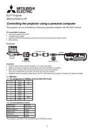
C. Application Note for <strong>LAN</strong> based communicationThe RS-232C command code is been able to execute on <strong>LAN</strong>.When you make your application program, you use socket port as a TCP/IP client.Please refer general technical documents (commercially available) of network control.Preparation of system setup(1) Connect with the PC, the displays and <strong>LAN</strong> HUB with <strong>LAN</strong> cable. (See page 2.)(2) The Main Power Switch (AC) of the display is ON. So the modes of the display are DCOn, DC Off or Standby.(3) The PC is on.(4) Set the OSD menu “<strong>LAN</strong> SETTING".DHCP CLIENTSelect whether to use DHCP client or not.Select OFF when not using it, and select ON when using it.IP ADDRESSSet the IP address of the monitor.Default address is 192.168.0.10. (It depends on model.)SUBNET MASKSet the gateway mask.Set it to 255.255.255.0 for normal use.DEFAULT GATEWAYSet the IP address of the gateway router to externally connect the local areaincluding the monitor.Default address is 192.168.0.1. (It depends on each model.)(5) Read the OSD menu “<strong>LAN</strong> SETTING" for control program.PORTRead the port number.Default number is 63007. (It depends on model. MDT652S 63007 or 3007)<strong>Communication</strong> protocol order(1) Open socket port ‘63007’ of the display IP address on the PC as a TCP/IP client.(On Windows PC, the port is “Winsock”. On Linux PC, the port is “socket”.)(2) Send RS-232C command code on TCP/IP protocol from the PC.(Sending ‘Read command’ at first is recommended for confirming communicationcondition and display condition.)(3) Receive RS-232C command code on TCP/IP protocol from the display.Note: This <strong>LAN</strong> command protocol has no NETWORK CERTIFICATION feature. When you don’t usein private network, you may change the IP address sometimes for low level security.(55/56)
All data are subject to change without notice.Copyright 2008-2011 <strong>Mitsubishi</strong> <strong>Electric</strong>Corporation All Right ReservedThis document provides the technical information for users. <strong>Mitsubishi</strong> <strong>Electric</strong>Corporation reserves the right to change or modify the information containedherein without notice. <strong>Mitsubishi</strong> <strong>Electric</strong>Corporation makes no warranty for the use of its products and bears no responsibility for any errors or omissions whichmay appear in this document.(56/56)