The Design of Rolling Bearing Mountings
The Design of Rolling Bearing Mountings The Design of Rolling Bearing Mountings
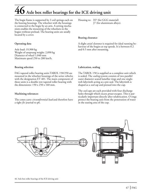
46 Axle box roller bearings for the ICE driving unitThe bogie frame is supported by 2 coil springs each onthe bearing housings. The wheelset with the housingsis connected to the bogie by an arm. A setting mechanismenables the mounting of the wheelsets in thebogies without preload. The bearing units are axiallylocated by a cover.Operating dataAxle load: 19,900 kgWeight of unsprung weight: 2,090 kgDiameter of wheel 1,040 mmMaximum speed 250 to 280 km/h.Housing to:Bearing clearanceH7 (for GGG material)J7 (for aluminium alloys).A slight axial clearance is required for ideal running behaviourof the bogies at top speeds. It is between 0.2and 0.5 mm after mounting.Bearing selectionFAG tapered roller bearing units TAROL 150/250 aremounted in the wheelset housings of the series vehicleswith the designation ET 401. The main component ofthese units is a double row tapered roller bearing withthe dimensions: 150 x 250 x 160 mm.Machining tolerancesThe cones carry circumferential load and therefore havea tight fit: journal to p6.Lubrication, sealingThe TAROL 150 is supplied as a complete unit whichis sealed. The sealing system consists of two parallelouter diameter seated lamellar rings and one singleweblabyrinth acting as a pre-seal. The labyrinth isshaped as a seal cap and pressed into the cup.The seal caps are each provided with four dischargeholes through which excess grease escapes. This is particularlyimportant directly after relubrication. O ringsprotect the bearing unit from the penetration of waterin the seating area of the cup.46: Axle box roller bearings of the ICE driving unit67 FAG
47Axle box roller bearingsof the Channel tunnel's freight engine, class 92Class 92 is used for freight traffic in the Euro tunnelbetween Great Britain and the Continent. It is a twosystemengine which means it can be operated on directcurrent (750 V) as well as on alternating current(25 kV). The engine with six axles (CoCo) draws loadsweighing up to 1,600 t.The vertical loads of the bogie are accommodated bytwo lateral coil springs on the housing of the axle boxbearings. All lateral and longitudinal forces act via theguiding journals and sleeves which are attached to thebogie frame and the housing.The middle axle of each triple axle bogie is designed asa floating axle box to insure trouble-free operation innarrow curves. The two outer axles are designed asstandard axles as customary.Operating dataVehicle weight 126,000 kg; two bogies each with threeaxles; wheel diameter 1,120 mm; top speed v max =140 km/h;Power P = 5,000 kW at 25 kV AC4,000 kW at 750 V DCBearing selectionTapered roller bearing units TAROL 150/250 withpressed cages (JP) are mounted to the outer standardaxles of the vehicles. The bearings are clearance-adjusted,greased and sealed by the manufacturer. Fey lamellarrings provide for sealing on the side facing thewheel. A gap-type seal prevents rough dirt from penetratingthe bearings.The floating axle is accommodated in two cylindricalroller bearings whose dimensions are 150 x 250 x80 mm. The extended inner ring allows axial displacementwithin the bearing of ± 20 mm at a maximum.Sealing is achieved at the wheel end by means of longwebbedlabyrinths.Machining tolerancesThe inner rings carry circumferential load and have atight fit to p6 on the journal.The housing bores (point load ) are machined accordingto H7.Bearing clearancePrior to mounting, the TAROL units of the standardaxle have an axial clearance of 0.665...0.740 mm andthe cylindrical roller bearing units a radial clearance toC4 in order to compensate for heat expansion.LubricationBoth bearing types are lubricated with a lithium soapbase grease. While the lubricant in the TAROL bearingsis only changed during the main inspections, thefloating axle bearings must be relubricated in between.Due to the constant right to left displacement of theaxle lubricant is removed from the bearing area andtherefore has to be replaced regularly.FAG 68
- Page 18: 7: Rotor bearing arrangement of a m
- Page 21 and 22: 9-18 Work spindles of machine tools
- Page 23 and 24: 10 NC-lathe main spindleOperating d
- Page 26 and 27: 13 High-speed motor milling spindle
- Page 28 and 29: 15 Vertical high-speed milling spin
- Page 30 and 31: 17 External cylindrical grinding sp
- Page 32 and 33: 19 Rotary table of a vertical lathe
- Page 34 and 35: 21 Rough-turning lathe for round ba
- Page 36 and 37: 22: Flywheel bearing arrangement of
- Page 38 and 39: 24 Double-shaft circular sawOperati
- Page 40 and 41: Rollbending bearingsA counterbendin
- Page 42 and 43: 27 Spur gear transmission for a rev
- Page 44 and 45: The effects of basing the bearing d
- Page 46 and 47: 29 Bevel gear - spur gear transmiss
- Page 48 and 49: 31 Worm gear pairOperating dataInpu
- Page 50 and 51: at least normal cleanliness (contam
- Page 52 and 53: 33 Manual gearbox for trucksOperati
- Page 54: 34 Final drive of a passenger carOp
- Page 57 and 58: Driven and non-steered rear wheel36
- Page 59 and 60: 38 Steering king pin of a truckA va
- Page 61 and 62: 40 Water pump for passenger car and
- Page 63 and 64: 42 Axle box roller bearings of an I
- Page 65 and 66: 43-44 UIC axle box roller bearings
- Page 67: 45Axle box roller bearingsof series
- Page 71 and 72: 48 Axle box roller bearings for an
- Page 73 and 74: 50Axle box roller bearingsaccording
- Page 75 and 76: 52Universal quill drivefor threepha
- Page 77 and 78: 54 Spur gear transmission for the u
- Page 79 and 80: 55 Bevel gear transmission for city
- Page 81 and 82: 56- 57 Spherical roller bearings as
- Page 83 and 84: 60 Spade-type rudderDesignThe slewi
- Page 85 and 86: 61-62 Ship shaft bearings and stern
- Page 87 and 88: 63-64 Ship shaft thrust blocksThe t
- Page 89 and 90: 64a: Complete ship shaft thrust blo
- Page 91 and 92: 65 RefinersWood chips from the wood
- Page 93 and 94: 66 Suction rollsSuction rolls are f
- Page 95 and 96: 68 Dryer rollsThe remaining water i
- Page 97 and 98: 69 Guide rollsGuide rolls guide, as
- Page 99 and 100: 70 Calender thermo rollsThe paper p
- Page 101 and 102: 71 Anti-deflection rollsAnti-deflec
- Page 103 and 104: 73 Run wheel of a material ropewayO
- Page 105 and 106: 74 Rope return sheaves of a passeng
- Page 107 and 108: 75 Rope sheave (underground mining)
- Page 109 and 110: 76 Rope sheave of a pulley blockIn
- Page 111 and 112: 77 Crane pillar mounting with a sph
- Page 113 and 114: 79 Roller track assemblyThe radial
- Page 115 and 116: 80 Crane run wheelOperating dataWhe
- Page 117 and 118: 81 Crane hookThe load suspended fro
46 Axle box roller bearings for the ICE driving unit<strong>The</strong> bogie frame is supported by 2 coil springs each onthe bearing housings. <strong>The</strong> wheelset with the housingsis connected to the bogie by an arm. A setting mechanismenables the mounting <strong>of</strong> the wheelsets in thebogies without preload. <strong>The</strong> bearing units are axiallylocated by a cover.Operating dataAxle load: 19,900 kgWeight <strong>of</strong> unsprung weight: 2,090 kgDiameter <strong>of</strong> wheel 1,040 mmMaximum speed 250 to 280 km/h.Housing to:<strong>Bearing</strong> clearanceH7 (for GGG material)J7 (for aluminium alloys).A slight axial clearance is required for ideal running behaviour<strong>of</strong> the bogies at top speeds. It is between 0.2and 0.5 mm after mounting.<strong>Bearing</strong> selectionFAG tapered roller bearing units TAROL 150/250 aremounted in the wheelset housings <strong>of</strong> the series vehicleswith the designation ET 401. <strong>The</strong> main component <strong>of</strong>these units is a double row tapered roller bearing withthe dimensions: 150 x 250 x 160 mm.Machining tolerances<strong>The</strong> cones carry circumferential load and therefore havea tight fit: journal to p6.Lubrication, sealing<strong>The</strong> TAROL 150 is supplied as a complete unit whichis sealed. <strong>The</strong> sealing system consists <strong>of</strong> two parallelouter diameter seated lamellar rings and one singleweblabyrinth acting as a pre-seal. <strong>The</strong> labyrinth isshaped as a seal cap and pressed into the cup.<strong>The</strong> seal caps are each provided with four dischargeholes through which excess grease escapes. This is particularlyimportant directly after relubrication. O ringsprotect the bearing unit from the penetration <strong>of</strong> waterin the seating area <strong>of</strong> the cup.46: Axle box roller bearings <strong>of</strong> the ICE driving unit67 FAG


