The Design of Rolling Bearing Mountings
The Design of Rolling Bearing Mountings The Design of Rolling Bearing Mountings
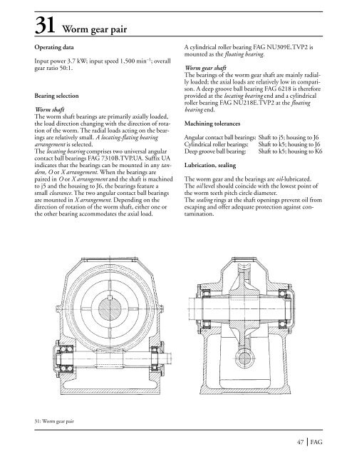
31 Worm gear pairOperating dataInput power 3.7 kW; input speed 1,500 min –1 ; overallgear ratio 50:1.Bearing selectionWorm shaftThe worm shaft bearings are primarily axially loaded,the load direction changing with the direction of rotationof the worm. The radial loads acting on the bearingsare relatively small. A locating-flating bearingarrangement is selected.The locating bearing comprises two universal angularcontact ball bearings FAG 7310B.TVP.UA. Suffix UAindicates that the bearings can be mounted in any tandem,O or X arrangement. When the bearings arepaired in O or X arrangement and the shaft is machinedto j5 and the housing to J6, the bearings feature asmall clearance. The two angular contact ball bearingsare mounted in X arrangement. Depending on thedirection of rotation of the worm shaft, either one orthe other bearing accommodates the axial load.A cylindrical roller bearing FAG NU309E.TVP2 ismounted as the floating bearing.Worm gear shaftThe bearings of the worm gear shaft are mainly radiallyloaded; the axial loads are relatively low in comparison.A deep groove ball bearing FAG 6218 is thereforeprovided at the locating bearing end and a cylindricalroller bearing FAG NU218E.TVP2 at the floatingbearing end.Machining tolerancesAngular contact ball bearings: Shaft to j5; housing to J6Cylindrical roller bearings: Shaft to k5; housing to J6Deep groove ball bearing: Shaft to k5; housing to K6Lubrication, sealingThe worm gear and the bearings are oil-lubricated.The oil level should coincide with the lowest point ofthe worm teeth pitch circle diameter.The sealing rings at the shaft openings prevent oil fromescaping and offer adequate protection against contamination.31: Worm gear pair47 FAG
32–33 Automotive gearboxesDesignThe rolling bearings used in torque converters in vehicles(manual transmissions and transfer boxes) are custom-tailoredto this application. Depending on theload accommodation and speed requirements, deepgroove ball bearings – both unshielded and dirt-protected("clean bearings") –, cylindrical roller bearings,combined bearings and tapered roller bearings haveproven themselves in the main bearing locations. Theidlers are generally supported on needle roller and cageassemblies. The main bearing locations have locatingfloatingbearing designs, adjusted bearing or floatingbearing arrangements.Locating-floating bearing arrangementRadial loads are accommodated by both bearings whilethe axial load is taken up by the locating bearing. Withextreme axial loads the radial and axial loads may betaken up separately (axial bearing e. g. deep groove ballbearing or four-point bearing) at the locating bearingend.Adjusted bearing arrangementThe angular contact ball bearings or tapered rollerbearings are mounted in opposition to one another.The bearings, when running at operating temperature,should have zero clearance or even preload (narrowaxial guidance). Regulation of the axial clearance byaxial displacement of the bearing rings. Both bearingsaccommodate radial and axial loads.Floating bearing arrangementThe bearings (except for angular contact bearings, allbearing types may be used) accommodate both radialand axial loads, permitting, however, axial displacementof the shaft. This axial displaceability is such thatthe bearings are never preloaded, not even under adversethermal conditions.LubricationThe gear wheels of vehicle transmissions are all oil-lubricatedalmost without exception. For this reason oillubrication is usually also provided for the rolling bearingsin the transmission.Since the rolling bearings require only very little lubricant,the oil splashed from the gear wheels is normallysufficient for bearing lubrication. Only in cases wherethe splash oil does not reach the bearings may it benecessary to provide collecting pockets and feed ducts.On the other hand it is advisable to protect those bearingswhich run directly beside the gear wheel from excessiveoil supply, for example by means of a seal or abaffle plate.However, with joint lubrication of gear wheels andbearings care must be taken that the life-reducing contaminantsare filtered out of the oil circulation (costly).Dirt-protected bearingsIn order to keep these contaminants (rubbed-off particlesfrom the gears) out of the bearings as long as possible,manual transmissions for cars are fitted todaywith sealed, grease-lubricated deep groove ball bearingsor angular contact ball bearings (so-called dirt-protectedor "clean bearings").Since roller bearings are less affected by cycled particles,the dirt-protected design is not required in automotivegearboxes.Bearing selection and dimensioningThe bearing calculation is based on the maximum inputtorque with the corresponding speed, the gearingdata and the proportionate running times for the individualgear steps.Determination of the tooth loadsBased on the tangential load F t = M d / r a radial load(F r = F t · tan E ) and an axial load (F a = F t · tan ) arecalculated. Based on the distances at the individualshafts, the forces acting on the teeth are distributedover the individual bearing locations, also taking intoaccount the tilting moment caused by the tooth loadcomponent F a .Index of dynamic stressing f LUnsealed transmission bearings in medium-weight toheavy cars should have an f Lm value of 1.0...1.3, whereasthe f Lm value for dirt-protected bearings should be0.7...1.0.The bearing loads in the individual speeds and thetransmission bearings are calculated in detail by meansof computer programs.Attainable lifeThe lubricant in open ball bearings must be assumedto be moderately (contamination factor V = 2) to heavilycontaminated (V = 3) .With the usual transmission bearing stress indexes off s* ≈ 2...8, depending on the gear, a cleanliness factor ofs = 0.6...0.7 is obtained with V = 2, and s = 0.3...0.5with V = 3.Consequently, due to the effects of contamination by thetransmission oil, the reserve capacities of the unsealedball bearings (higher f Lm value) cannot be utilized. Onthe other hand, if dirt-protected ball bearings are used,FAG 48
- Page 3: PrefaceThis publication presents de
- Page 6 and 7: ContentsExample Title . . . . . . .
- Page 8 and 9: assembly is contracted. Thus the ra
- Page 10 and 11: Current insulationWhere converter c
- Page 12 and 13: 4 Electric motor for domestic appli
- Page 14 and 15: PulleyDrum5: Drum mounting of a dom
- Page 16 and 17: 6: Rotor bearing arrangement of a v
- Page 18: 7: Rotor bearing arrangement of a m
- Page 21 and 22: 9-18 Work spindles of machine tools
- Page 23 and 24: 10 NC-lathe main spindleOperating d
- Page 26 and 27: 13 High-speed motor milling spindle
- Page 28 and 29: 15 Vertical high-speed milling spin
- Page 30 and 31: 17 External cylindrical grinding sp
- Page 32 and 33: 19 Rotary table of a vertical lathe
- Page 34 and 35: 21 Rough-turning lathe for round ba
- Page 36 and 37: 22: Flywheel bearing arrangement of
- Page 38 and 39: 24 Double-shaft circular sawOperati
- Page 40 and 41: Rollbending bearingsA counterbendin
- Page 42 and 43: 27 Spur gear transmission for a rev
- Page 44 and 45: The effects of basing the bearing d
- Page 46 and 47: 29 Bevel gear - spur gear transmiss
- Page 50 and 51: at least normal cleanliness (contam
- Page 52 and 53: 33 Manual gearbox for trucksOperati
- Page 54: 34 Final drive of a passenger carOp
- Page 57 and 58: Driven and non-steered rear wheel36
- Page 59 and 60: 38 Steering king pin of a truckA va
- Page 61 and 62: 40 Water pump for passenger car and
- Page 63 and 64: 42 Axle box roller bearings of an I
- Page 65 and 66: 43-44 UIC axle box roller bearings
- Page 67 and 68: 45Axle box roller bearingsof series
- Page 69 and 70: 47Axle box roller bearingsof the Ch
- Page 71 and 72: 48 Axle box roller bearings for an
- Page 73 and 74: 50Axle box roller bearingsaccording
- Page 75 and 76: 52Universal quill drivefor threepha
- Page 77 and 78: 54 Spur gear transmission for the u
- Page 79 and 80: 55 Bevel gear transmission for city
- Page 81 and 82: 56- 57 Spherical roller bearings as
- Page 83 and 84: 60 Spade-type rudderDesignThe slewi
- Page 85 and 86: 61-62 Ship shaft bearings and stern
- Page 87 and 88: 63-64 Ship shaft thrust blocksThe t
- Page 89 and 90: 64a: Complete ship shaft thrust blo
- Page 91 and 92: 65 RefinersWood chips from the wood
- Page 93 and 94: 66 Suction rollsSuction rolls are f
- Page 95 and 96: 68 Dryer rollsThe remaining water i
- Page 97 and 98: 69 Guide rollsGuide rolls guide, as
31 Worm gear pairOperating dataInput power 3.7 kW; input speed 1,500 min –1 ; overallgear ratio 50:1.<strong>Bearing</strong> selectionWorm shaft<strong>The</strong> worm shaft bearings are primarily axially loaded,the load direction changing with the direction <strong>of</strong> rotation<strong>of</strong> the worm. <strong>The</strong> radial loads acting on the bearingsare relatively small. A locating-flating bearingarrangement is selected.<strong>The</strong> locating bearing comprises two universal angularcontact ball bearings FAG 7310B.TVP.UA. Suffix UAindicates that the bearings can be mounted in any tandem,O or X arrangement. When the bearings arepaired in O or X arrangement and the shaft is machinedto j5 and the housing to J6, the bearings feature asmall clearance. <strong>The</strong> two angular contact ball bearingsare mounted in X arrangement. Depending on thedirection <strong>of</strong> rotation <strong>of</strong> the worm shaft, either one orthe other bearing accommodates the axial load.A cylindrical roller bearing FAG NU309E.TVP2 ismounted as the floating bearing.Worm gear shaft<strong>The</strong> bearings <strong>of</strong> the worm gear shaft are mainly radiallyloaded; the axial loads are relatively low in comparison.A deep groove ball bearing FAG 6218 is thereforeprovided at the locating bearing end and a cylindricalroller bearing FAG NU218E.TVP2 at the floatingbearing end.Machining tolerancesAngular contact ball bearings: Shaft to j5; housing to J6Cylindrical roller bearings: Shaft to k5; housing to J6Deep groove ball bearing: Shaft to k5; housing to K6Lubrication, sealing<strong>The</strong> worm gear and the bearings are oil-lubricated.<strong>The</strong> oil level should coincide with the lowest point <strong>of</strong>the worm teeth pitch circle diameter.<strong>The</strong> sealing rings at the shaft openings prevent oil fromescaping and <strong>of</strong>fer adequate protection against contamination.31: Worm gear pair47 FAG


