The Design of Rolling Bearing Mountings
The Design of Rolling Bearing Mountings The Design of Rolling Bearing Mountings
24 Double-shaft circular sawOperating dataInput power max. 200 kW;max. speed 2,940 min –1 .The cylindrical roller bearing FAG NU1026M at thedrive end is the floating bearing. Heat expansion in theaxial direction is freely accommodated in the bearing.The cylindrical roller bearing also accommodates thehigh belt pull tension forces.Bearing selectionA simple bearing arrangement is required with standardizedbearings which are suitable for very highspeeds and allow accurate shaft guidance. The requiredhigh shaft rigidity determines the bearing bore diameter.The locating bearing is at the work end in order to keepheat expansion in the axial direction as small as possibleat this end. The two spindle bearings FAGB7030E.T.P4S.UL are mounted in O arrangement.The bearings of the UL universal design are lightly preloadedby clamping the inner rings axially. The bearingpair is suitable for high speeds.Machining tolerancesShaft tolerance js5Housing tolerance JS6Lubrication, sealingThe bearings are greased for life, e.g. with FAG rollingbearing grease Arcanol L74V.Good sealing is required due to the dust arising duringsawing. Non-rubbing seals are used due to the highspeed. Flinger disks prevent the penetration of coarsecontaminants into the gap-type seals.24: Double-shaft circular saw37 FAG
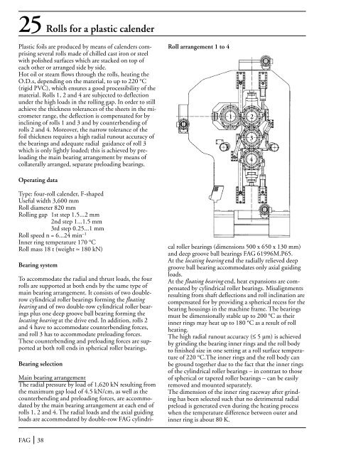
25 Rolls for a plastic calenderPlastic foils are produced by means of calenders comprisingseveral rolls made of chilled cast iron or steelwith polished surfaces which are stacked on top ofeach other or arranged side by side.Hot oil or steam flows through the rolls, heating theO.D.s, depending on the material, to up to 220 °C(rigid PVC), which ensures a good processibility of thematerial. Rolls 1, 2 and 4 are subjected to deflectionunder the high loads in the rolling gap. In order to stillachieve the thickness tolerances of the sheets in the micrometerrange, the deflection is compensated for byinclining of rolls 1 and 3 and by counterbending ofrolls 2 and 4. Moreover, the narrow tolerance of thefoil thickness requires a high radial runout accuracy ofthe bearings and adequate radial guidance of roll 3which is only lightly loaded; this is achieved by preloadingthe main bearing arrangement by means ofcollaterally arranged, separate preloading bearings.Roll arrangement 1 to 41 234Operating dataType: four-roll calender, F-shapedUseful width 3,600 mmRoll diameter 820 mmRolling gap 1st step 1.5...2 mm2nd step 1...1.5 mm3rd step 0.25...1 mmRoll speed n = 6...24 min –1Inner ring temperature 170 °CRoll mass 18 t (weight ≈ 180 kN)Bearing systemTo accommodate the radial and thrust loads, the fourrolls are supported at both ends by the same type ofmain bearing arrangement. It consists of two doublerowcylindrical roller bearings forming the floatingbearing and of two double-row cylindrical roller bearingsplus one deep groove ball bearing forming thelocating bearing at the drive end. In addition, rolls 2and 4 have to accommodate counterbending forces,and roll 3 has to accommodate preloading forces.These counterbending and preloading forces are supportedat both roll ends in spherical roller bearings.Bearing selectionMain bearing arrangementThe radial pressure by load of 1,620 kN resulting fromthe maximum gap load of 4.5 kN/cm, as well as thecounterbending and preloading forces, are accommodatedby the main bearing arrangement at each end ofrolls 1, 2 and 4. The radial loads and the axial guidingloads are accommodated by double-row FAG cylindricalroller bearings (dimensions 500 x 650 x 130 mm)and deep groove ball bearings FAG 61996M.P65.At the locating bearing end the radially relieved deepgroove ball bearing accommodates only axial guidingloads.At the floating bearing end, heat expansions are compensatedby cylindrical roller bearings. Misalignmentsresulting from shaft deflections and roll inclination arecompensated for by providing a spherical recess for thebearing housings in the machine frame. The bearingsmust be dimensionally stable up to 200 °C as theirinner rings may heat up to 180 °C as a result of rollheating.The high radial runout accuracy (≤ 5 µm) is achievedby grinding the bearing inner rings and the roll bodyto finished size in one setting at a roll surface temperatureof 220 °C.The inner rings and the roll body canbe ground together due to the fact that the inner ringsof the cylindrical roller bearings – in contrast to thoseof spherical or tapered roller bearings – can be easilyremoved and mounted separately.The dimension of the inner ring raceway after grindinghas been selected such that no detrimental radialpreload is generated even during the heating processwhen the temperature difference between outer andinner ring is about 80 K.FAG 38
- Page 3: PrefaceThis publication presents de
- Page 6 and 7: ContentsExample Title . . . . . . .
- Page 8 and 9: assembly is contracted. Thus the ra
- Page 10 and 11: Current insulationWhere converter c
- Page 12 and 13: 4 Electric motor for domestic appli
- Page 14 and 15: PulleyDrum5: Drum mounting of a dom
- Page 16 and 17: 6: Rotor bearing arrangement of a v
- Page 18: 7: Rotor bearing arrangement of a m
- Page 21 and 22: 9-18 Work spindles of machine tools
- Page 23 and 24: 10 NC-lathe main spindleOperating d
- Page 26 and 27: 13 High-speed motor milling spindle
- Page 28 and 29: 15 Vertical high-speed milling spin
- Page 30 and 31: 17 External cylindrical grinding sp
- Page 32 and 33: 19 Rotary table of a vertical lathe
- Page 34 and 35: 21 Rough-turning lathe for round ba
- Page 36 and 37: 22: Flywheel bearing arrangement of
- Page 40 and 41: Rollbending bearingsA counterbendin
- Page 42 and 43: 27 Spur gear transmission for a rev
- Page 44 and 45: The effects of basing the bearing d
- Page 46 and 47: 29 Bevel gear - spur gear transmiss
- Page 48 and 49: 31 Worm gear pairOperating dataInpu
- Page 50 and 51: at least normal cleanliness (contam
- Page 52 and 53: 33 Manual gearbox for trucksOperati
- Page 54: 34 Final drive of a passenger carOp
- Page 57 and 58: Driven and non-steered rear wheel36
- Page 59 and 60: 38 Steering king pin of a truckA va
- Page 61 and 62: 40 Water pump for passenger car and
- Page 63 and 64: 42 Axle box roller bearings of an I
- Page 65 and 66: 43-44 UIC axle box roller bearings
- Page 67 and 68: 45Axle box roller bearingsof series
- Page 69 and 70: 47Axle box roller bearingsof the Ch
- Page 71 and 72: 48 Axle box roller bearings for an
- Page 73 and 74: 50Axle box roller bearingsaccording
- Page 75 and 76: 52Universal quill drivefor threepha
- Page 77 and 78: 54 Spur gear transmission for the u
- Page 79 and 80: 55 Bevel gear transmission for city
- Page 81 and 82: 56- 57 Spherical roller bearings as
- Page 83 and 84: 60 Spade-type rudderDesignThe slewi
- Page 85 and 86: 61-62 Ship shaft bearings and stern
- Page 87 and 88: 63-64 Ship shaft thrust blocksThe t
25 Rolls for a plastic calenderPlastic foils are produced by means <strong>of</strong> calenders comprisingseveral rolls made <strong>of</strong> chilled cast iron or steelwith polished surfaces which are stacked on top <strong>of</strong>each other or arranged side by side.Hot oil or steam flows through the rolls, heating theO.D.s, depending on the material, to up to 220 °C(rigid PVC), which ensures a good processibility <strong>of</strong> thematerial. Rolls 1, 2 and 4 are subjected to deflectionunder the high loads in the rolling gap. In order to stillachieve the thickness tolerances <strong>of</strong> the sheets in the micrometerrange, the deflection is compensated for byinclining <strong>of</strong> rolls 1 and 3 and by counterbending <strong>of</strong>rolls 2 and 4. Moreover, the narrow tolerance <strong>of</strong> thefoil thickness requires a high radial runout accuracy <strong>of</strong>the bearings and adequate radial guidance <strong>of</strong> roll 3which is only lightly loaded; this is achieved by preloadingthe main bearing arrangement by means <strong>of</strong>collaterally arranged, separate preloading bearings.Roll arrangement 1 to 41 234Operating dataType: four-roll calender, F-shapedUseful width 3,600 mmRoll diameter 820 mm<strong>Rolling</strong> gap 1st step 1.5...2 mm2nd step 1...1.5 mm3rd step 0.25...1 mmRoll speed n = 6...24 min –1Inner ring temperature 170 °CRoll mass 18 t (weight ≈ 180 kN)<strong>Bearing</strong> systemTo accommodate the radial and thrust loads, the fourrolls are supported at both ends by the same type <strong>of</strong>main bearing arrangement. It consists <strong>of</strong> two doublerowcylindrical roller bearings forming the floatingbearing and <strong>of</strong> two double-row cylindrical roller bearingsplus one deep groove ball bearing forming thelocating bearing at the drive end. In addition, rolls 2and 4 have to accommodate counterbending forces,and roll 3 has to accommodate preloading forces.<strong>The</strong>se counterbending and preloading forces are supportedat both roll ends in spherical roller bearings.<strong>Bearing</strong> selectionMain bearing arrangement<strong>The</strong> radial pressure by load <strong>of</strong> 1,620 kN resulting fromthe maximum gap load <strong>of</strong> 4.5 kN/cm, as well as thecounterbending and preloading forces, are accommodatedby the main bearing arrangement at each end <strong>of</strong>rolls 1, 2 and 4. <strong>The</strong> radial loads and the axial guidingloads are accommodated by double-row FAG cylindricalroller bearings (dimensions 500 x 650 x 130 mm)and deep groove ball bearings FAG 61996M.P65.At the locating bearing end the radially relieved deepgroove ball bearing accommodates only axial guidingloads.At the floating bearing end, heat expansions are compensatedby cylindrical roller bearings. Misalignmentsresulting from shaft deflections and roll inclination arecompensated for by providing a spherical recess for thebearing housings in the machine frame. <strong>The</strong> bearingsmust be dimensionally stable up to 200 °C as theirinner rings may heat up to 180 °C as a result <strong>of</strong> rollheating.<strong>The</strong> high radial runout accuracy (≤ 5 µm) is achievedby grinding the bearing inner rings and the roll bodyto finished size in one setting at a roll surface temperature<strong>of</strong> 220 °C.<strong>The</strong> inner rings and the roll body canbe ground together due to the fact that the inner rings<strong>of</strong> the cylindrical roller bearings – in contrast to those<strong>of</strong> spherical or tapered roller bearings – can be easilyremoved and mounted separately.<strong>The</strong> dimension <strong>of</strong> the inner ring raceway after grindinghas been selected such that no detrimental radialpreload is generated even during the heating processwhen the temperature difference between outer andinner ring is about 80 K.FAG 38


