
Create successful ePaper yourself
Turn your PDF publications into a flip-book with our unique Google optimized e-Paper software.
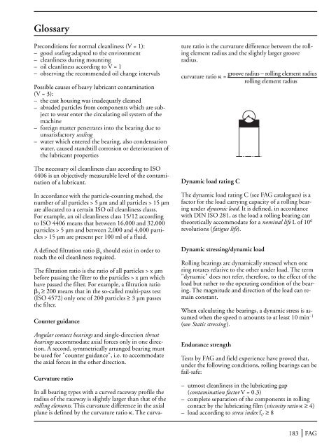
GlossaryPreconditions for normal cleanliness (V = 1):– good sealing adapted to the environment– cleanliness during mounting– oil cleanliness according to V = 1– observing the recommended oil change intervalsPossible causes <strong>of</strong> heavy lubricant contamination(V = 3):– the cast housing was inadequatly cleaned– abraded particles from components which are subjectto wear enter the circulating oil system <strong>of</strong> themachine– foreign matter penetrates into the bearing due tounsatisfactory sealing– water which entered the bearing, also condensationwater, caused standstill corrosion or deterioration <strong>of</strong>the lubricant properties<strong>The</strong> necessary oil cleanliness class according to ISO4406 is an objectively measurable level <strong>of</strong> the contamination<strong>of</strong> a lubricant.In accordance with the particle-counting mehod, thenumber <strong>of</strong> all particles > 5 µm and all particles > 15 µmare allocated to a certain ISO oil cleanliness classs.For example, an oil cleanliness class 15/12 accordingto ISO 4406 means that between 16,000 and 32,000particles > 5 µm and between 2,000 and 4,000 particles> 15 µm are present per 100 ml <strong>of</strong> a fluid.A defined filtration ratio x should exist in order toreach the oil cleanliness required.<strong>The</strong> filtration ratio is the ratio <strong>of</strong> all particles > x µmbefore passing the filter to the particles > x µm whichhave passed the filter. For example, a filtration ratio 3 ≥ 200 means that in the so-called multi-pass test(ISO 4572) only one <strong>of</strong> 200 particles ≥ 3 µm passesthe filter.Counter guidanceAngular contact bearings and single-direction thrustbearings accommodate axial forces only in one direction.A second, symmetrically arranged bearing mustbe used for "counter guidance", i.e. to accommodatethe axial forces in the other direction.Curvature ratioIn all bearing types with a curved raceway pr<strong>of</strong>ile theradius <strong>of</strong> the raceway is slightly larger than that <strong>of</strong> therolling elements. This curvature difference in the axialplane is defined by the curvature ratio . <strong>The</strong> curvatureratio is the curvature difference between the rollingelement radius and the slightly larger grooveradius.curvature ratio =groove radius – rolling element radiusrolling element radiusDynamic load rating C<strong>The</strong> dynamic load rating C (see FAG catalogues) is afactor for the load carrying capacity <strong>of</strong> a rolling bearingunder dynamic load. It is defined, in accordancewith DIN ISO 281, as the load a rolling bearing cantheoretically accommodate for a nominal life L <strong>of</strong> 10 6revolutions (fatigue life).Dynamic stressing/dynamic load<strong>Rolling</strong> bearings are dynamically stressed when onering rotates relative to the other under load. <strong>The</strong> term"dynamic" does not refer, therefore, to the effect <strong>of</strong> theload but rather to the operating condition <strong>of</strong> the bearing.<strong>The</strong> magnitude and direction <strong>of</strong> the load can remainconstant.When calculating the bearings, a dynamic stress is assumedwhen the speed n amounts to at least 10 min –1(see Static stressing ).Endurance strengthTests by FAG and field experience have proved that,under the following conditions, rolling bearings can befail-safe:– utmost cleanliness in the lubricating gap(contamination factor V = 0.3)– complete separation <strong>of</strong> the components in rollingcontact by the lubricating film (viscosity ratio ≥ 4)– load according to stress index f s* ≥ 8183 FAG