The Design of Rolling Bearing Mountings
The Design of Rolling Bearing Mountings The Design of Rolling Bearing Mountings
107: Combined reduction and cogging wheel gear of a billet mill151 FAG
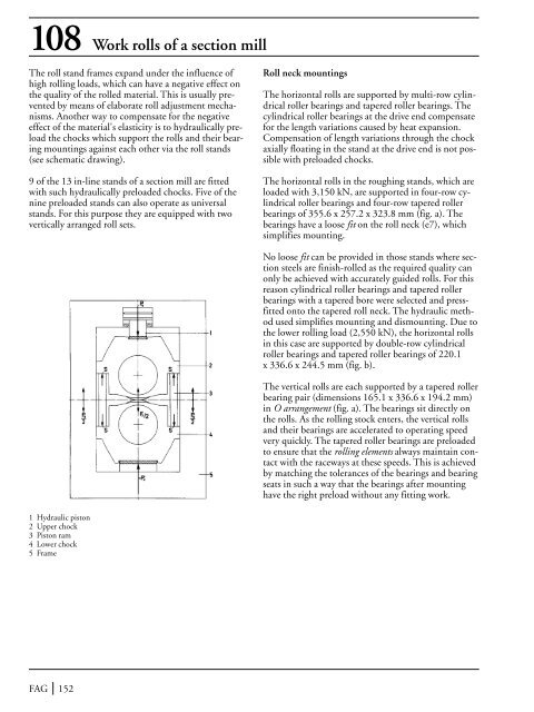
108 Work rolls of a section millThe roll stand frames expand under the influence ofhigh rolling loads, which can have a negative effect onthe quality of the rolled material. This is usually preventedby means of elaborate roll adjustment mechanisms.Another way to compensate for the negativeeffect of the material's elasticity is to hydraulically preloadthe chocks which support the rolls and their bearingmountings against each other via the roll stands(see schematic drawing).9 of the 13 in-line stands of a section mill are fittedwith such hydraulically preloaded chocks. Five of thenine preloaded stands can also operate as universalstands. For this purpose they are equipped with twovertically arranged roll sets.Roll neck mountingsThe horizontal rolls are supported by multi-row cylindricalroller bearings and tapered roller bearings. Thecylindrical roller bearings at the drive end compensatefor the length variations caused by heat expansion.Compensation of length variations through the chockaxially floating in the stand at the drive end is not possiblewith preloaded chocks.The horizontal rolls in the roughing stands, which areloaded with 3,150 kN, are supported in four-row cylindricalroller bearings and four-row tapered rollerbearings of 355.6 x 257.2 x 323.8 mm (fig. a). Thebearings have a loose fit on the roll neck (e7), whichsimplifies mounting.No loose fit can be provided in those stands where sectionsteels are finish-rolled as the required quality canonly be achieved with accurately guided rolls. For thisreason cylindrical roller bearings and tapered rollerbearings with a tapered bore were selected and pressfittedonto the tapered roll neck. The hydraulic methodused simplifies mounting and dismounting. Due tothe lower rolling load (2,550 kN), the horizontal rollsin this case are supported by double-row cylindricalroller bearings and tapered roller bearings of 220.1x 336.6 x 244.5 mm (fig. b).The vertical rolls are each supported by a tapered rollerbearing pair (dimensions 165.1 x 336.6 x 194.2 mm)in O arrangement (fig. a). The bearings sit directly onthe rolls. As the rolling stock enters, the vertical rollsand their bearings are accelerated to operating speedvery quickly. The tapered roller bearings are preloadedto ensure that the rolling elements always maintain contactwith the raceways at these speeds. This is achievedby matching the tolerances of the bearings and bearingseats in such a way that the bearings after mountinghave the right preload without any fitting work.1 Hydraulic piston2 Upper chock3 Piston ram4 Lower chock5 FrameFAG 152
- Page 101 and 102: 71 Anti-deflection rollsAnti-deflec
- Page 103 and 104: 73 Run wheel of a material ropewayO
- Page 105 and 106: 74 Rope return sheaves of a passeng
- Page 107 and 108: 75 Rope sheave (underground mining)
- Page 109 and 110: 76 Rope sheave of a pulley blockIn
- Page 111 and 112: 77 Crane pillar mounting with a sph
- Page 113 and 114: 79 Roller track assemblyThe radial
- Page 115 and 116: 80 Crane run wheelOperating dataWhe
- Page 117 and 118: 81 Crane hookThe load suspended fro
- Page 119 and 120: 83 Head pulley of a belt conveyorOn
- Page 121 and 122: Internal bearings for the tension/8
- Page 123 and 124: Belt conveyor idlersMany industries
- Page 125 and 126: 87 Bucket wheel shaft of a bucket w
- Page 127 and 128: 89 Drive unit of a finished goods e
- Page 129 and 130: 91 Vibrating road rollerThe vibrati
- Page 131 and 132: 92 Double toggle jaw crusherDouble
- Page 133 and 134: 94 Double-shaft hammer crusherDoubl
- Page 135 and 136: 95 Ball tube millTube mills are mos
- Page 137 and 138: 96 Support roller of a rotary kilnR
- Page 139 and 140: Vibrating machinesVibrating screens
- Page 141 and 142: 98 Two-bearing screen with straight
- Page 143 and 144: 99 Four-bearing screenThe vibration
- Page 145 and 146: 101-103 Large capacity convertersCo
- Page 147 and 148: 104Roll bearings of afour-high cold
- Page 149 and 150: Work rolls for the finishing sectio
- Page 151: 107 Combined reduction and cogging
- Page 155 and 156: Two-high rolls of a dressing stand1
- Page 157 and 158: 110 Straightening rolls of a rail s
- Page 159 and 160: 111 Disk ploughIn a disk plough the
- Page 161 and 162: 112 Plane sifterSifters are used in
- Page 163 and 164: Printing pressesPrinting quality is
- Page 165 and 166: 114 Blanket cylinder of a sheet-fed
- Page 167 and 168: 116 Axial piston machineCylinder bl
- Page 169 and 170: 117 Axial piston machineOperating d
- Page 171 and 172: 119 Hot gas fanGas temperature 150
- Page 173 and 174: 121 Optical telescopeOperating data
- Page 175 and 176: 122-124 RadiotelescopeFor radioastr
- Page 177 and 178: 123 Azimuth axis (track roller and
- Page 179 and 180: GlossaryAdditivesAdditives are oil-
- Page 181 and 182: GlossaryAxial clearanceThe axial cl
- Page 183 and 184: GlossaryContamination factor VThe c
- Page 185 and 186: GlossaryEP additivesWear-reducing a
- Page 187 and 188: Glossary1. Safe retention and unifo
- Page 189 and 190: GlossaryLoad angleThe load angle i
- Page 191 and 192: Glossaryload and the ring to be fit
- Page 193 and 194: Glossaryaligning ball bearings, bar
- Page 195 and 196: GlossaryViscosityViscosity is the m
- Page 197 and 198: NotesFAG 196
108 Work rolls <strong>of</strong> a section mill<strong>The</strong> roll stand frames expand under the influence <strong>of</strong>high rolling loads, which can have a negative effect onthe quality <strong>of</strong> the rolled material. This is usually preventedby means <strong>of</strong> elaborate roll adjustment mechanisms.Another way to compensate for the negativeeffect <strong>of</strong> the material's elasticity is to hydraulically preloadthe chocks which support the rolls and their bearingmountings against each other via the roll stands(see schematic drawing).9 <strong>of</strong> the 13 in-line stands <strong>of</strong> a section mill are fittedwith such hydraulically preloaded chocks. Five <strong>of</strong> thenine preloaded stands can also operate as universalstands. For this purpose they are equipped with twovertically arranged roll sets.Roll neck mountings<strong>The</strong> horizontal rolls are supported by multi-row cylindricalroller bearings and tapered roller bearings. <strong>The</strong>cylindrical roller bearings at the drive end compensatefor the length variations caused by heat expansion.Compensation <strong>of</strong> length variations through the chockaxially floating in the stand at the drive end is not possiblewith preloaded chocks.<strong>The</strong> horizontal rolls in the roughing stands, which areloaded with 3,150 kN, are supported in four-row cylindricalroller bearings and four-row tapered rollerbearings <strong>of</strong> 355.6 x 257.2 x 323.8 mm (fig. a). <strong>The</strong>bearings have a loose fit on the roll neck (e7), whichsimplifies mounting.No loose fit can be provided in those stands where sectionsteels are finish-rolled as the required quality canonly be achieved with accurately guided rolls. For thisreason cylindrical roller bearings and tapered rollerbearings with a tapered bore were selected and pressfittedonto the tapered roll neck. <strong>The</strong> hydraulic methodused simplifies mounting and dismounting. Due tothe lower rolling load (2,550 kN), the horizontal rollsin this case are supported by double-row cylindricalroller bearings and tapered roller bearings <strong>of</strong> 220.1x 336.6 x 244.5 mm (fig. b).<strong>The</strong> vertical rolls are each supported by a tapered rollerbearing pair (dimensions 165.1 x 336.6 x 194.2 mm)in O arrangement (fig. a). <strong>The</strong> bearings sit directly onthe rolls. As the rolling stock enters, the vertical rollsand their bearings are accelerated to operating speedvery quickly. <strong>The</strong> tapered roller bearings are preloadedto ensure that the rolling elements always maintain contactwith the raceways at these speeds. This is achievedby matching the tolerances <strong>of</strong> the bearings and bearingseats in such a way that the bearings after mountinghave the right preload without any fitting work.1 Hydraulic piston2 Upper chock3 Piston ram4 Lower chock5 FrameFAG 152


