The Design of Rolling Bearing Mountings
The Design of Rolling Bearing Mountings The Design of Rolling Bearing Mountings
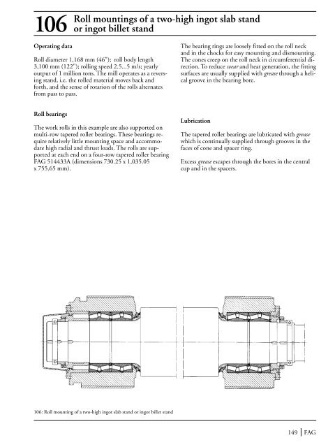
Roll mountings of a two-high ingot slab stand106 or ingot billet standOperating dataRoll diameter 1,168 mm (46"); roll body length3,100 mm (122"); rolling speed 2.5...5 m/s; yearlyoutput of 1 million tons. The mill operates as a reversingstand, i.e. the rolled material moves back andforth, and the sense of rotation of the rolls alternatesfrom pass to pass.The bearing rings are loosely fitted on the roll neckand in the chocks for easy mounting and dismounting.The cones creep on the roll neck in circumferential direction.To reduce wear and heat generation, the fittingsurfaces are usually supplied with grease through a helicalgroove in the bearing bore.Roll bearingsThe work rolls in this example are also supported onmulti-row tapered roller bearings. These bearings requirerelatively little mounting space and accommodatehigh radial and thrust loads. The rolls are supportedat each end on a four-row tapered roller bearingFAG 514433A (dimensions 730.25 x 1,035.05x 755.65 mm).LubricationThe tapered roller bearings are lubricated with greasewhich is continually supplied through grooves in thefaces of cone and spacer ring.Excess grease escapes through the bores in the centralcup and in the spacers.106: Roll mounting of a two-high ingot slab stand or ingot billet stand149 FAG
107 Combined reduction and cogging wheel gear of a billet millOperating dataThe billet mill is designed for a monthly output of55,000 tons. The mill comprises a roughing and a finishingsection, each with two vertical and two horizontalstands in alternate arrangement. The drive of thevertical stands is on top; with this arrangement thefoundations are not as deep as for a bottom drive; onthe other hand, the top drive involves a greater overallheight.Rated horsepower 1,100/2,200 kW;motor speed 350/750 min –1 .Compared to two angular contact ball bearings, a fourpoint bearing offers the advantage of smaller widthand, compared to a deep groove ball bearing, the advantageof smaller axial clearance and higher thrust carryingcapacity. The use of four point bearings is, however,limited to applications where the thrust load isnot constantly reversing. The bevel gear shafts featurethe smallest possible axial clearance to ensure perfectmeshing of the spiral-toothed gears. This is achievedby one duplex pair of angular contact ball bearingseach on the pinion shaft and on the bevel shaft. Theyalso accommodate the thrust load whereas the radialload is taken up by cylindrical roller bearings.Machining tolerancesBearing selection, dimensioningRadial loads and thrust loads are accommodated separately:the radial loads by cylindrical roller bearings, thethrust loads by angular contact ball bearings and fourpoint bearings. Cylindrical roller bearings offer thebest radial load carrying capacity in a limited mountingspace, thus keeping the distance between the gearshafts to a minimum. One decisive factor in the selectionof the bearing size is the diameter of the individualgear shafts determined in the strength calculation.The two largest cylindrical roller bearings of the gearare situated on the cogging wheel side and have thefollowing dimensions: 750 x 1,000 x 250 mm. Axiallocation of the four gear shafts is provided by one fourpoint bearing each which are double direction angularcontact ball bearings.Cylindrical roller bearings: Shaft to p6; housing toH6/H7.Four point bearings and angular contact ball bearings:Shaft to f6; housing to D10.The outer rings of the four point bearings and angularcontact ball bearings are fitted into the housing withclearance to relieve them of radial loads; thus, they accommodateonly thrust loads.LubricationCirculating oil lubrication. The bearings and gearsshare the same lubrication system. The oil is directlysupplied to the bearings via an oil filter which preventscontamination of the bearings by particles abradedfrom the gears.FAG 150
- Page 99 and 100: 70 Calender thermo rollsThe paper p
- Page 101 and 102: 71 Anti-deflection rollsAnti-deflec
- Page 103 and 104: 73 Run wheel of a material ropewayO
- Page 105 and 106: 74 Rope return sheaves of a passeng
- Page 107 and 108: 75 Rope sheave (underground mining)
- Page 109 and 110: 76 Rope sheave of a pulley blockIn
- Page 111 and 112: 77 Crane pillar mounting with a sph
- Page 113 and 114: 79 Roller track assemblyThe radial
- Page 115 and 116: 80 Crane run wheelOperating dataWhe
- Page 117 and 118: 81 Crane hookThe load suspended fro
- Page 119 and 120: 83 Head pulley of a belt conveyorOn
- Page 121 and 122: Internal bearings for the tension/8
- Page 123 and 124: Belt conveyor idlersMany industries
- Page 125 and 126: 87 Bucket wheel shaft of a bucket w
- Page 127 and 128: 89 Drive unit of a finished goods e
- Page 129 and 130: 91 Vibrating road rollerThe vibrati
- Page 131 and 132: 92 Double toggle jaw crusherDouble
- Page 133 and 134: 94 Double-shaft hammer crusherDoubl
- Page 135 and 136: 95 Ball tube millTube mills are mos
- Page 137 and 138: 96 Support roller of a rotary kilnR
- Page 139 and 140: Vibrating machinesVibrating screens
- Page 141 and 142: 98 Two-bearing screen with straight
- Page 143 and 144: 99 Four-bearing screenThe vibration
- Page 145 and 146: 101-103 Large capacity convertersCo
- Page 147 and 148: 104Roll bearings of afour-high cold
- Page 149: Work rolls for the finishing sectio
- Page 153 and 154: 108 Work rolls of a section millThe
- Page 155 and 156: Two-high rolls of a dressing stand1
- Page 157 and 158: 110 Straightening rolls of a rail s
- Page 159 and 160: 111 Disk ploughIn a disk plough the
- Page 161 and 162: 112 Plane sifterSifters are used in
- Page 163 and 164: Printing pressesPrinting quality is
- Page 165 and 166: 114 Blanket cylinder of a sheet-fed
- Page 167 and 168: 116 Axial piston machineCylinder bl
- Page 169 and 170: 117 Axial piston machineOperating d
- Page 171 and 172: 119 Hot gas fanGas temperature 150
- Page 173 and 174: 121 Optical telescopeOperating data
- Page 175 and 176: 122-124 RadiotelescopeFor radioastr
- Page 177 and 178: 123 Azimuth axis (track roller and
- Page 179 and 180: GlossaryAdditivesAdditives are oil-
- Page 181 and 182: GlossaryAxial clearanceThe axial cl
- Page 183 and 184: GlossaryContamination factor VThe c
- Page 185 and 186: GlossaryEP additivesWear-reducing a
- Page 187 and 188: Glossary1. Safe retention and unifo
- Page 189 and 190: GlossaryLoad angleThe load angle i
- Page 191 and 192: Glossaryload and the ring to be fit
- Page 193 and 194: Glossaryaligning ball bearings, bar
- Page 195 and 196: GlossaryViscosityViscosity is the m
- Page 197 and 198: NotesFAG 196
Roll mountings <strong>of</strong> a two-high ingot slab stand106 or ingot billet standOperating dataRoll diameter 1,168 mm (46"); roll body length3,100 mm (122"); rolling speed 2.5...5 m/s; yearlyoutput <strong>of</strong> 1 million tons. <strong>The</strong> mill operates as a reversingstand, i.e. the rolled material moves back andforth, and the sense <strong>of</strong> rotation <strong>of</strong> the rolls alternatesfrom pass to pass.<strong>The</strong> bearing rings are loosely fitted on the roll neckand in the chocks for easy mounting and dismounting.<strong>The</strong> cones creep on the roll neck in circumferential direction.To reduce wear and heat generation, the fittingsurfaces are usually supplied with grease through a helicalgroove in the bearing bore.Roll bearings<strong>The</strong> work rolls in this example are also supported onmulti-row tapered roller bearings. <strong>The</strong>se bearings requirerelatively little mounting space and accommodatehigh radial and thrust loads. <strong>The</strong> rolls are supportedat each end on a four-row tapered roller bearingFAG 514433A (dimensions 730.25 x 1,035.05x 755.65 mm).Lubrication<strong>The</strong> tapered roller bearings are lubricated with greasewhich is continually supplied through grooves in thefaces <strong>of</strong> cone and spacer ring.Excess grease escapes through the bores in the centralcup and in the spacers.106: Roll mounting <strong>of</strong> a two-high ingot slab stand or ingot billet stand149 FAG


