
You also want an ePaper? Increase the reach of your titles
YUMPU automatically turns print PDFs into web optimized ePapers that Google loves.
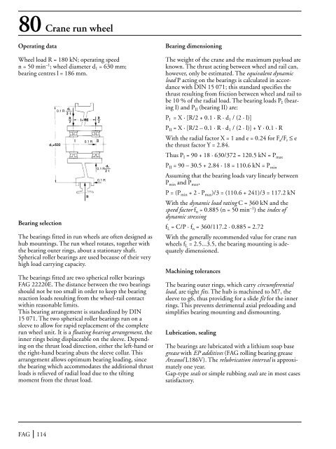
80 Crane run wheelOperating dataWheel load R = 180 kN; operating speedn = 50 min –1 ; wheel diameter d 1 = 630 mm;bearing centres l = 186 mm.0.1 R0.1 R<strong>Bearing</strong> dimensioning<strong>The</strong> weight <strong>of</strong> the crane and the maximum payload areknown. <strong>The</strong> thrust acting between wheel and rail can,however, only be estimated. <strong>The</strong> equivalent dynamicload P acting on the bearings is calculated in accordancewith DIN 15 071; this standard specifies thethrust resulting from friction between wheel and rail tobe 10 % <strong>of</strong> the radial load. <strong>The</strong> bearing loads P I (bearingI) and P II (bearing II) are:P I = X · [R/2 + 0.1 · R · d 1 / (2 · l)]P II = X · [R/2 – 0.1 · R · d 1 / (2 · l)] + Y · 0.1 · RWith the radial factor X = 1 and e = 0.24 for F a /F r ≤ ethe thrust factor Y = 2.84.Thus P I = 90 + 18 · 630/372 = 120.5 kN = P max<strong>Bearing</strong> selection0.1 R0.1 R<strong>The</strong> bearings fitted in run wheels are <strong>of</strong>ten designed ashub mountings. <strong>The</strong> run wheel rotates, together withthe bearing outer rings, about a stationary shaft.Spherical roller bearings are used because <strong>of</strong> their veryhigh load carrying capacity.<strong>The</strong> bearings fitted are two spherical roller bearingsFAG 22220E. <strong>The</strong> distance between the two bearingsshould not be too small in order to keep the bearingreaction loads resulting from the wheel-rail contactwithin reasonable limits.This bearing arrangement is standardized by DIN15 071. <strong>The</strong> two spherical roller bearings run on asleeve to allow for rapid replacement <strong>of</strong> the completerun wheel unit. It is a floating bearing arrangement, theinner rings being displaceable on the sleeve. Dependingon the thrust load direction, either the left-hand orthe right-hand bearing abuts the sleeve collar. Thisarrangement allows optimum bearing loading, sincethe bearing which accommodates the additional thrustloads is relieved <strong>of</strong> radial load due to the tiltingmoment from the thrust load.P II = 90 – 30.5 + 2.84 · 18 = 110.6 kN = P minAssuming that the bearing loads vary linearly betweenP min and P max ,P = (P min + 2 · P max )/3 = (110.6 + 241)/3 = 117.2 kNWith the dynamic load rating C = 360 kN and thespeed factor f n = 0.885 (n = 50 min –1 ) the index <strong>of</strong>dynamic stressingf L = C/P · f n = 360/117.2 · 0.885 = 2.72With the generally recommended value for crane runwheels f L = 2.5...3.5, the bearing mounting is adequatelydimensioned.Machining tolerances<strong>The</strong> bearing outer rings, which carry circumferentialload, are tight fits. <strong>The</strong> hub is machined to M7, thesleeve to g6, thus providing for a slide fit for the innerrings. This prevents detrimental axial preloading andsimplifies bearing mounting and dismounting.Lubrication, sealing<strong>The</strong> bearings are lubricated with a lithium soap basegrease with EP additives (FAG rolling bearing greaseArcanol L186V). <strong>The</strong> relubrication interval is approximatelyone year.Gap-type seals or simple rubbing seals are in most casessatisfactory.FAG 114