
Create successful ePaper yourself
Turn your PDF publications into a flip-book with our unique Google optimized e-Paper software.
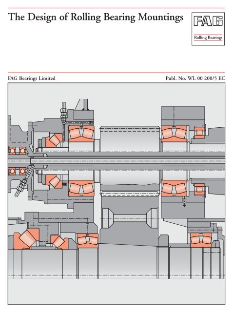
PrefaceThis publication presents design examples coveringvarious machines, vehicles and equipment having onething in common: rolling bearings.For this reason the brief texts concentrate on the rollingbearing aspects <strong>of</strong> the applications. <strong>The</strong> operation<strong>of</strong> the machine allows conclusions to be drawn aboutthe operating conditions which dictate the bearingtype and design, the size and arrangement, fits, lubricationand sealing.Important rolling bearing engineering terms are printedin italics. At the end <strong>of</strong> this publication they aresummarized and explained in a glossary <strong>of</strong> terms, somesupplemented by illustrations.FAG 2
ContentsExample TitleSHIPBUILDINGPageRudder shafts . . . . . . . . . . . . . . . . . . . . . . 7956-57 Spherical roller bearings as ruddershaft bearings . . . . . . . . . . . . . . . . . . . . . . . 8058-59 Spherical roller thrust bearings asrudder carriers . . . . . . . . . . . . . . . . . . . . . . 8160 Spade-type rudder . . . . . . . . . . . . . . . . . . . 82Ship shafts61-62 Ship shaft bearings and stern tubebearings . . . . . . . . . . . . . . . . . . . . . . . . . . . 8463-64 Ship shaft thrust blocks . . . . . . . . . . . . . . 86PAPER MACHINES . . . . . . . . . . . . . . . 8965 Refiners . . . . . . . . . . . . . . . . . . . . . . . . . . . 9066 Suction rolls . . . . . . . . . . . . . . . . . . . . . . . 9267 Central press rolls . . . . . . . . . . . . . . . . . . . 9368 Dryer rolls . . . . . . . . . . . . . . . . . . . . . . . . . 9469 Guide rolls . . . . . . . . . . . . . . . . . . . . . . . . 9670 Calender thermo rolls . . . . . . . . . . . . . . . . 9871 Anti-deflection rolls . . . . . . . . . . . . . . . . 10072 preader rolls . . . . . . . . . . . . . . . . . . . . . . 101LIFTING AND CONVEYINGEQUIPMENTAerial ropeways, rope sheaves73 Run wheel <strong>of</strong> a material ropeway . . . . . . 10274 Rope return sheaves <strong>of</strong> passengerropeway . . . . . . . . . . . . . . . . . . . . . . . . . . 10475 Rope sheave (underground mining) . . . . 10676 Rope sheave <strong>of</strong> a pulley block . . . . . . . . . 108Cranes, lift trucks77 Crane pillar mounting with a sphericalroller thrust bearing . . . . . . . . . . . . . . . . 11078 Crane pillar mounting with a sphericalroller thrust bearing and a sphericalroller bearing . . . . . . . . . . . . . . . . . . . . . . 11179 Roller track assembly . . . . . . . . . . . . . . . 11280 Crane run wheel . . . . . . . . . . . . . . . . . . . 11481 Crane hook . . . . . . . . . . . . . . . . . . . . . . . 11682 Mast guidance bearings <strong>of</strong> afork lift truck . . . . . . . . . . . . . . . . . . . . . 117Belt conveyors83 Head pulley <strong>of</strong> a belt conveyor . . . . . . . . 11884 Internal bearings for the tension/take-up pulley <strong>of</strong> a belt conveyor . . . . . . 12085 Rigid idlers . . . . . . . . . . . . . . . . . . . . . . . 12286 Idler garland . . . . . . . . . . . . . . . . . . . . . . 123Example TitlePageExcavators and bucket elevators87 Bucket wheel shaft <strong>of</strong> a bucket wheelexcavator . . . . . . . . . . . . . . . . . . . . . . . . . 12488 Bottom sprocket <strong>of</strong> a bucket chaindredger . . . . . . . . . . . . . . . . . . . . . . . . . . 12589 Drive unit <strong>of</strong> a finished-goods elevator . 126CONSTRUCTION MACHINERY90 Driving axle <strong>of</strong> a construction machine . 12791 Vibrating road roller . . . . . . . . . . . . . . . . 128RAW MATERIAL PROCESSINGCrushers and mills92 Double toggle jaw crusher . . . . . . . . . . . 13093 Hammer mill . . . . . . . . . . . . . . . . . . . . . 13194 Double-shaft hammer crusher . . . . . . . . 13295 Ball tube mill . . . . . . . . . . . . . . . . . . . . . 13496 Support roller <strong>of</strong> a rotary kiln . . . . . . . . . 136Vibrating machines . . . . . . . . . . . . . . . . 13897 Two-bearing screen with circle throw . . . 13998 Two-bearing screen with straight-linemotion . . . . . . . . . . . . . . . . . . . . . . . . . . 14099 Four-bearing screen . . . . . . . . . . . . . . . . 142100 Vibrator motor . . . . . . . . . . . . . . . . . . . . 143STEEL MILL AND ROLLING MILLEQUIPMENT101-103 Large-capacity converters . . . . . . . . . . . . 144104 Roll bearings <strong>of</strong> a non-reversing fourhighcold rolling stand for aluminium . . 146105 Work rolls for the finishing section <strong>of</strong> afour-high hot wide strip mill . . . . . . . . . 148106 Roll mountings <strong>of</strong> a two-high ingotslab stand or ingot billet stand . . . . . . . . 149107 Combined reduction and coggingwheel gear <strong>of</strong> a billet mill . . . . . . . . . . . . 150108 Work rolls <strong>of</strong> a section mill . . . . . . . . . . . 152109 Two-high rolls <strong>of</strong> a dressing stand forcopper and brass bands . . . . . . . . . . . . . . 154110 Straightening rolls <strong>of</strong> a rail straightener . 156AGRICULTURAL MACHINERY ·FOOD INDUSTRY111 Disk plough . . . . . . . . . . . . . . . . . . . . . . 158112 Plane sifter . . . . . . . . . . . . . . . . . . . . . . . 160FAG 4
ContentsExample Title . . . . . . . . . . . . . . . . . . . . . . . . . . . .PagePRINTING PRESSES113 Impression cylinders <strong>of</strong> a newspaperrotary printing press . . . . . . . . . . . . . . . . 162114 Blanket cylinder <strong>of</strong> a sheet-fed <strong>of</strong>fsetpress . . . . . . . . . . . . . . . . . . . . . . . . . . . . 164PUMPS115 Centrifugal pump . . . . . . . . . . . . . . . . . . 165116-117 Axial piston machines . . . . . . . . . . . . . . . 166VENTILATORS, COMPRESSORS,FANS118 Exhauster . . . . . . . . . . . . . . . . . . . . . . . . 169119 Hot gas fan . . . . . . . . . . . . . . . . . . . . . . . 170120 Fresh air blower . . . . . . . . . . . . . . . . . . . . 171PRECISION MECHANICS,OPTICS, ANTENNAS121 Optical telescope . . . . . . . . . . . . . . . . . . 172Radiotelescope . . . . . . . . . . . . . . . . . . . . 174122 Elevation axle . . . . . . . . . . . . . . . . . . . . . 175123 Azimuth axis (track roller and kingpin bearings) . . . . . . . . . . . . . . . . . . . . . . 176124 Data wheel . . . . . . . . . . . . . . . . . . . . . . . 177GLOSSARY . . . . . . . . . . . . . . . . . . . . . 1785 FAG
1 Traction motor for electric standard-gauge locomotivesOperating dataThree-phase current motor supplied by frequencyconverter.Nominal output 1,400 kW, maximum speed4,300 min –1 (maximum driving speed for transmissionswith standard gear ratios is 200 km/h). One-enddrive with herringbone gear pinion.<strong>Bearing</strong> selection, dimensioningCollective loads which cover representative load casesfor the motor torque, speeds, and percentages <strong>of</strong> timefor the operating conditions in question, are used todetermine bearing stressing.Load case . . . . . . . . . . . . . . . . . . . . . . . . . . . . . . . . .M d n . . . . . . . . . . . . . . . . . . . . . . . . . . . . . . . .qN m . . . . . . . . . . . . . . . . . . . . . . . . . . . . . .min –1 %1 6,720 . . . . . . . . . . . . . . . . . . . . . . . . . . . . .1,056 22 2,240 . . . . . . . . . . . . . . . . . . . . . . . . . . . . .1,690 343 1,920 . . . . . . . . . . . . . . . . . . . . . . . . . . . . .2,324 184 3,200 . . . . . . . . . . . . . . . . . . . . . . . . . . . . .2,746 425 2,240 . . . . . . . . . . . . . . . . . . . . . . . . . . . . .4,225 6<strong>The</strong> collective load is the basis for determining theaverage speeds (2,387 min –1 ) and the average drivingspeed (111 km/h). For each <strong>of</strong> the load cases the toothload acting on the pinion and the reaction loads fromthe bearings have to be calculated both for forward andbackward motion (percentage times 50 % each).In addition to these forces, the bearings are subjectedto loads due to the rotor weight, the unbalanced magneticpull, unbalanced loads and rail shocks. Of theseloads only the rotor weight, G L , is known; therefore, itis multiplied by a supplementary factor f z = 1.5...2.5 –depending on the type <strong>of</strong> motor suspension. <strong>The</strong> bearingloads are determined from this estimated load. Forthe spring-suspended traction motor shown, a supplementaryfactor f z = 1.5 is used.<strong>The</strong> bearing loads from weight and drive allow the resultantbearing loading to be determined by vectoraddition. In this example only the critical transmission-endbearing will be discussed. <strong>The</strong> attainable lifeL hna1...5 is determined for every load case using the formulaL hna = a 1 · a 23 · L h [h], taking into account theoperating viscosity <strong>of</strong> the transmission oil at 120 °C,the rated viscosity 1 as well as the factors K 1 and K 2 .<strong>The</strong> basic a 23II factor is between 0.8 and 3. <strong>The</strong> cleanlinessfactor s is assumed to be 1. <strong>The</strong>n, L hna is obtainedusing the formula:L hna =100q 1 q + 2L hna1 L hna2q + 3L hna3+ ...When selecting the bearing it should be ensured thatthe nominal mileage is reached and that, due to thehigh speed, the drive-end bearing is not too large.With the bearings selected the theoretical mileage <strong>of</strong>2.5 million kilometers required by the customer can bereached.A cylindrical roller bearing FAG NU322E.TVP2.C5.F1serves as floating bearing at the drive end; an FAG566513 with an angle ring HJ318E.F1 serves as thelocating bearing.<strong>The</strong> cylindrical roller bearing FAG 566513 is anNJ318E.TVP2.P64.F1, but its inner ring is 6 mmwider. <strong>The</strong> resulting axial clearance <strong>of</strong> 6 mm is requiredin order to allow the herringbone gearing on thepinion to align freely.Suffixes:ETVP2C5F1P64reinforced designmoulded cage <strong>of</strong> glass fibre reinforcedpolyamide, rolling element ridingradial clearance larger than C4FAG manufacturing and inspectionspecification for cylindrical roller bearings intraction motors which considers, amongothers, the requirements according to DIN43283 "Cylindrical roller bearings forelectric traction".tolerance class P6, radial clearance C4Machining tolerancesDrive end: shaft r5; end cap to M6Opposite end: shaft n5; end cap to M6<strong>The</strong> bearings are fitted tightly on the shaft due to thehigh load, which is sometimes <strong>of</strong> the shock type. Thisreduces the danger <strong>of</strong> fretting corrosion, particularly atthe drive end.<strong>Bearing</strong> clearanceDue to the tight fits, the inner ring <strong>of</strong> the bearing isexpanded and the outer ring with the roller-and-cageFAG 6
assembly is contracted. Thus the radial clearance <strong>of</strong> thebearing is reduced after mounting. It is further reducedduring operation as the operating temperature<strong>of</strong> the inner ring is higher than that <strong>of</strong> the outer ring.For this reason bearings with an increased radial clearance(C4...C5) are mounted.Lubrication, sealing<strong>The</strong> drive-end bearing is lubricated, due to the highspeeds, with transmission oil ISO VG 320 with EPadditives. No sealing is required between pinion andbearing so that a shorter cantilever can be used, thusreducing the bearing loading. Flinger edges and oilcollecting grooves prevent the oil from escaping in thedirection <strong>of</strong> the coil.1: Traction motor for electric standard-gauge locomotive7 FAG
2 Traction motor for electric commuter trains<strong>The</strong> bearing at the opposite end is lubricated with alithium soap base grease <strong>of</strong> NLGI penetration class 3(FAG rolling bearing grease Arcanol L71V).<strong>The</strong> bearings should be relubricated after 400,000 kilometersor five years, respectively. Multiple labyrinthsprevent contaminants from penetrating into the bearings.Operating dataSelf-ventilated converter current motor, permanentpower 200 kW at a speed <strong>of</strong> 1,820 min –1 (drivingspeed 72 km/h), maximum speed 3,030 min –1 (maximumdriving speed 120 km/h), one-end drive withherringbone gear pinion.<strong>Bearing</strong> selection, dimensioning<strong>The</strong> operating mode <strong>of</strong> commuter train motor vehiclesis characterized by the short distances between stops.<strong>The</strong> periodic operating conditions – starting, driving,braking – can be recorded on an operating graph representingthe motor torque versus the driving time.<strong>The</strong> cubic mean <strong>of</strong> the motor torque and an averagespeed, which is also determined from the operatinggraph, form the basis for the rolling bearing analysis.<strong>The</strong> mean torque is about 90 % <strong>of</strong> the torque at constantpower.<strong>The</strong> bearing loads are calculated as for traction motorsfor standard-gauge locomotives (example 1). <strong>The</strong>y aremade up <strong>of</strong> the reaction loads resulting from the gearforce on the driving pinion and a theoretical radialload which takes into account the rotor weight, themagnetic pull, unbalanced loads and rail shocks. Thistheoretical radial load applied at the rotor centre <strong>of</strong>gravity is calculated by multiplying the rotor weight bythe supplementary factor f z = 2. <strong>The</strong> value 2 takes intoaccount the relatively rigid motor suspension.An overhung pinion provides the drive. At the pinionend a cylindrical roller bearing FAG NU320E.M1.P64.F1is mounted as the floating bearing. At the commutatorend a deep groove ball bearing FAG 6318M.P64.J20Avery safely accommodates the thrust load resultingfrom the 7° helical gearing <strong>of</strong> the pinion, even at relativelyhigh speeds.FAG 8
Current insulationWhere converter current motors with an output <strong>of</strong>more than 100 kW are used, ripple voltages can becaused by magnetic asymmetries. As a result, an inducedcircuit is generated between rotor shaft and statorwhich can cause current passage damage in thebearing.To interrupt the flow <strong>of</strong> current, one bearing (in thiscase the deep groove ball bearing) is provided with currentinsulation.Current-insulated bearings feature an oxide ceramiccoating on the outer ring O.D.s and faces.Ventilation endDrive end2: Traction motor <strong>of</strong> an electric commuter train9 FAG
3 Three-phase current standard motorOperating dataBelt drive: Power 3 kW; rotor mass 8 kg; nominalspeed 2,800 min –1 ; size 100 L; totally enclosed fancooledaccording to DIN 42673, sheet 1 – design B3,type <strong>of</strong> protection IP44, insulation class F.<strong>Bearing</strong> selectionLow-noise bearings in a simple, maintenance-freearrangement should be provided. <strong>The</strong>se requirementsare best met by deep groove ball bearings.In DIN 42673, the shaft-end diameter specified forsize 100 L is 28 mm. Consequently, a bore diameter <strong>of</strong>30 mm is required. In this case a bearing <strong>of</strong> series 62was selected for both bearing locations, i.e. an FAG6206.2ZR.C3.L207. <strong>The</strong>y guide the rotor shaft bothat the drive side and at the ventilating side. <strong>The</strong> springat the drive side provides clearance-free adjustment <strong>of</strong>the bearings and accommodates opposing axial loadson the rotor shaft.By adjusting the deep groove ball bearings to zeroclearance the adverse influence <strong>of</strong> bearing clearance onnoise behaviour is eliminated.<strong>Bearing</strong> dimensioning<strong>The</strong> calculation <strong>of</strong> the bearings for this motor differssomewhat from the usual approach. As not even themotor manufacturer knows the amount <strong>of</strong> load at theshaft end, the permissible radial loading is indicated inthe motor catalogues.To determine the radial load carrying capacity, thedrive-side deep groove ball bearing is calculated.<strong>The</strong> calculation is based on an attainable life L hna <strong>of</strong>20,000 h and a basic a 23II value <strong>of</strong> 1.5. In addition, therotor weight, the unilateral magnetic pull and theunbalanced load have to be taken into account. As theDrive endlatter two criteria are not known the rotor weight issimply multiplied by a supplementary factor <strong>of</strong>f z = 1.5.With these values a permissible radial loading <strong>of</strong> 1 kNis calculated for the shaft-end middle.Since the operating load in most applications is lowerthan the admissible load, an attainable life L hna <strong>of</strong> morethan 20,000 hours is obtained. <strong>The</strong> life <strong>of</strong> electric motorbearings, therefore, is usually defined not by materialfatigue but by the grease service life.Suffixes.2ZRC3L207<strong>Bearing</strong> with two shieldsRadial clearance larger than PN (normal)Grease filling with Arcanol L207Machining tolerancesShaft to j5; end cap bore to H6.<strong>The</strong> bore tolerance H6 ensures the slide fit required forfree axial adjustment <strong>of</strong> both bearings.Lubrication, sealing<strong>The</strong> .2ZR design with shields on both bearing sideshas been successful in small and medium-sized electricmotors. <strong>The</strong> grease filling in these bearings is sufficientfor their entire service life. Increased operating temperaturesmust be taken into consideration in the case inquestion due to the insulation class F provided. Forthis reason the FAG high-temperature grease ArcanolL207 is used. <strong>The</strong> shields prevent the grease from escapingand protect the bearings from contaminationfrom the motor. Gap type seals protect the shaft openingat the drive side against dust and moisture. <strong>The</strong> requirementson insulation type IP44 are, therefore,met.Ventilation end3: Three-phase current standard motorFAG 10
4 Electric motor for domestic appliancesOperating dataPower 30 W; speed 3,500 min –1 .<strong>Bearing</strong> selectionQuiet running is the prime requirement for domesticappliance motors. <strong>The</strong> noise level <strong>of</strong> a motor is influencedby bearing quality (form and running accuracy),bearing clearance and the finish <strong>of</strong> the shaft and endcap bore.Today, the quality <strong>of</strong> standard bearings already adequatelymeets the common noise requirements.Zero-clearance operation <strong>of</strong> the bearings is achieved bya spring washer lightly preloading the bearings in theaxial direction.<strong>The</strong> bearing seats on the shaft and in the end cap boresmust be well aligned. To allow the spring washer toadjust the bearings axially, the outer rings have slide fitsin the end caps.A deep groove ball bearing FAG 626.2ZR is providedon the collector side, and an FAG 609.2ZR.L91 onthe other side.Suffixes.2ZR <strong>Bearing</strong> with shields on both sides; they form agap-type sealL91 special grease filling (Arcanol L91)<strong>Bearing</strong> dimensioning<strong>The</strong> shaft diameter is usually dictated by the machinedesign, and as a result the bearings are sufficiently dimensionedwith regard to fatigue life. Fatigue damagehardly ever occurs; the bearings reach the required life<strong>of</strong> between 500 and 2,000 hours.Machining tolerancesShaft to j5; end cap bore to H5<strong>The</strong> bore tolerance H5 provides the slide fit requiredto permit free axial alignment <strong>of</strong> both bearings.Sealing, lubricationGrease lubrication with lithium soap base grease <strong>of</strong> consistencynumber 2 with an especially high degree <strong>of</strong>cleanliness. It is characterized by its low friction. <strong>The</strong>overall efficiency <strong>of</strong> this motor is considerably influencedby the frictional moment <strong>of</strong> the ball bearings.<strong>The</strong> bearings with shields (.2ZR design) are prelubricatedwith grease, i.e. regreasing is not required. <strong>The</strong>gap-type seal formed by the shields <strong>of</strong>fers adequateprotection against contamination under normal ambientconditions.4: Electric motor for domestic appliances11 FAG
5 Drum <strong>of</strong> a domestic washing machineOperating data<strong>The</strong> bearing loads are:Capacity 4.5 kg dry mass <strong>of</strong> laundry(weight G w = 44 N);Speeds: when washing 50 min –1when spinning after prewash cycle 800 min –1when dry spinning 1,000 min –1<strong>Bearing</strong> AF rA =F · l 2[N]a<strong>Bearing</strong> selection<strong>The</strong> domestic washing machine is <strong>of</strong> the front loadingtype. <strong>The</strong> drum is overhung and pulley-driven.<strong>Bearing</strong> selection depends on the journal diameterwhich is determined by rigidity requirements, and alsoon the weight and unbalanced loads. Very simplifieddata is assumed for bearing load determination, onwhich the bearing dimensions are based, since loadsand speeds are variable.Domestic washing machines generally have several,partly automatic, washing cycles with or without spinning.During the actual washing cycle, i.e. a cyclewithout spinning, the drum bearings are only lightlyloaded by the weight resulting from drum and wetlaundry. This loading is unimportant for the bearingdimensioning and is thus neglected. <strong>The</strong> oppositeapplies to the spinning cycle: Since the laundry is unevenlydistributed around the drum circumference, anunbalanced load arises which, in turn, produces a largecentrifugal force. <strong>The</strong> bearing dimensioning is basedon this centrifugal force as well as on the weights <strong>of</strong> thedrum, G T , and the dry laundry, G w . <strong>The</strong> belt pull isgenerally neglected.<strong>The</strong> centrifugal force is calculated from:F Z = m · r · 2 [N]wherem = G U /g [N · s 2 /m]Unbalanced load [N]. 10...35 % <strong>of</strong> the drylaundry capacity is taken as unbalanced load.g Acceleration due to gravity = 9.81 m/s 2G UrRadius <strong>of</strong> action <strong>of</strong> unbalanced load [m]Drum radius = d T / 2 [m] Angular velocity = π · n / 30 [s –1 ]n Drum speed during spinning [min –1 ]<strong>The</strong> total force for determination <strong>of</strong> the bearing loadsthus is: F = F Z + G T + G W [N]This load is applied to the washing drum centre.<strong>Bearing</strong> dimensioning<strong>Bearing</strong> BF rB =F · l 1[N]a<strong>The</strong> bearings for domestic washing machines aredimensioned for an index <strong>of</strong> dynamic stressingf L = 0.85...1.0.<strong>The</strong>se values correspond to a nominal life <strong>of</strong>300...500 hours <strong>of</strong> spinning.In the example shown a deep groove ball bearing FAG6306.2ZR.C3 was selected for the drum side and adeep groove ball bearing FAG 6305.2ZR.C3 for thepulley side.<strong>The</strong> bearings have an increased radial clearance C3 andare sealed by shields (.2ZR) at both sides.Machining tolerancesDue to the unbalanced load G U ,the inner rings aresubjected to point load, the outer rings to circumferentialload. For this reason, the outer rings must have atight fit in the housing; this is achieved by machiningthe housing bores to M6. <strong>The</strong> fit <strong>of</strong> the inner rings isnot as tight; drum journal to h5. This ensures that thefloating bearing is able to adjust in the case <strong>of</strong> thermalexpansion. A loose fit also simplifies mounting.Lubrication, sealing<strong>The</strong> bearings, sealed at both sides, are prelubricatedwith a special grease, sufficient for the bearing servicelife. <strong>The</strong>re is an additional rubbing-type seal at thedrum side.FAG 12
PulleyDrum5: Drum mounting <strong>of</strong> a domestic washing machine13 FAG
6 Vertical-pump motorOperating dataRated horsepower 160 kW; nominal speed 3,000 min –1 ;Rotor and pump impeller mass 400 kg; pump thrust9 kN, directed downwards; type V1.<strong>Bearing</strong> selection<strong>The</strong> selection <strong>of</strong> the bearings is primarily based on themain thrust, which is directed downwards. It is madeup <strong>of</strong> the weight <strong>of</strong> the rotor and and pump impeller(4 kN), the pump thrust (9 kN) and the spring preload(1 kN). When the motor idles the pump thrust may bereversed so that the bearings have, briefly, to accommodatean upward axial load <strong>of</strong> 4 kN, as well.<strong>The</strong> radial loads acting on the bearings are not exactlyknown. <strong>The</strong>y are made up by the unbalanced magneticpull and potential unbalanced loads from the rotorand pump impeller. However, field experience showsthat these loads are sufficiently taken into account bytaking 50 % <strong>of</strong> the rotor and pump impeller mass,which in this case is 2 kN.In the example shown, the supporting bearing is anangular contact ball bearing FAG 7316B.TVP whichhas to accommodate the main thrust. To ensure thatno radial force acts on the bearing this part <strong>of</strong> thehousing is radially relieved to clearance fit E8.In normal operation, the deep groove ball bearingFAG 6216.C3 takes up only a light radial load and theaxial spring preload; in addition, the thrust reversalload <strong>of</strong> the idling motor has to be accommodated.As a result, the rotor is vertically displaced in the upwarddirection (ascending distance) which is limitedby the defined gap between deep groove ball bearingface and end cap. To avoid slippage during the thrustreversal stage, the angular contact ball bearing is subjectedto a minimum axial load by means <strong>of</strong> springs.On the pump impeller side a cylindrical roller bearingFAG NU1020M1.C3 acts as the floating bearing. As itaccommodates the unbalanced loads from the pumpimpeller both the inner and the outer ring are fittedtightly.<strong>The</strong> cylindrical roller bearing design depends on theshaft diameter <strong>of</strong> 100 mm, which in turn is dictated bystrength requirements. Due to the relatively light radialload, the lighter series NU10 was selected.Machining tolerancesCylindrical roller bearing: Shaft to m5; housingto M6Deep groove ball bearing: Shaft to k5; housingto H6Angular contact ball bearing: Shaft to k5, housingto E8Lubrication<strong>The</strong> bearings are lubricated with FAG rolling bearinggrease Arcanol L71V and can be relubricated.Replenishment quantity– for the floating bearing 15 g– for the locating bearing 40 g<strong>The</strong> relubrication interval is 1,000 hours. <strong>The</strong> spentgrease is collected in annular cover chambers providedbelow the bearing locations.FAG 14
6: Rotor bearing arrangement <strong>of</strong> a vertical-pump motor15 FAG
7 Mine fan motorOperating dataRated horsepower 1,800 kW; speed n = 750 min –1 ;Axial load F a = 130 kN; radial load F r = 3.5 kN;the bearings are vertically arranged.<strong>Bearing</strong> selection<strong>The</strong> axial load <strong>of</strong> 130 kN is made up <strong>of</strong> the weight <strong>of</strong>the rotor and the two variable top and bottom fan impellersas well as the thrust <strong>of</strong> these fan impellers. <strong>The</strong>yare supported by the upper thrust bearing.<strong>The</strong> radial loads on vertical motors are only guidingloads. <strong>The</strong>y are very small and generally result from theunbalanced magnetic pull and the potential rotor unbalancedload. In the example shown, the radial loadper bearing is 3.5 kN. If the exact values are notknown, these loads can be sufficiently taken intoaccount, assuming that half the rotor weight acts as theradial load at the rotor centre <strong>of</strong> gravity.<strong>The</strong> upper supporting bearing is a spherical rollerthrust bearing FAG 29260E.MB. Radial guidance isensured by a deep groove ball bearing FAG 16068Mmounted on the same sleeve as the supporting bearingand accommodating the opposing axial loads on therotor. Axial guidance is necessary for transporting andmounting as well as for motor idling. In this operatingcondition the counterflow <strong>of</strong> air can cause reversal <strong>of</strong>rotation and thrust. <strong>The</strong> axial displacement is limitedto 1 mm in the upward direction so that the sphericalroller thrust bearing does not lift <strong>of</strong>f. Springs arrangedbelow the housing washer (spring load 6 kN) ensurecontinuous contact in the bearings.Radial guidance at the lower bearing position is providedby a deep groove ball bearing FAG 6340M; it ismounted with a slide fit as the floating bearing. Sinceit is only lightly loaded, it is preloaded with springs <strong>of</strong>3 kN.<strong>Bearing</strong> dimensioningSpherical roller thrust bearing FAG 29260E.MB has adynamic load rating <strong>of</strong> C = 1430 kN. <strong>The</strong> index <strong>of</strong> dynamicstressing f L = 4.3 is calculated with the axial loadF a = 130 kN and the speed factor for roller bearingsf n = 0.393 (n = 750 min –1 ). <strong>The</strong> nominal lifeL h = 65,000 hours.Based on the operating viscosity <strong>of</strong> the lubricating oil(viscosity class ISO VG150) at approx. 70 °C, therated viscosity 1 and the factors K 1 und K 2 , a basic a 23IIvalue <strong>of</strong> about 3 is determined. <strong>The</strong> cleanliness factor sis assumed to be 1. <strong>The</strong> attainable life L hna <strong>of</strong> the thrustbearing is longer than 100,000 hours and the bearingis therefore sufficiently dimensioned. <strong>The</strong> two radialbearings are also sufficiently dimensioned with the index<strong>of</strong> dynamic stressing f L > 6.Machining tolerancesUpper bearing locationSpherical roller thrust bearing: Shaft to k5; housingto E8Deep groove ball bearing: Shaft to k5; housingto H6Lower bearing locationDeep groove ball bearing:Lubrication, sealingShaft to k5; housingto H6Thrust and radial bearings at the upper bearing locationare oil-lubricated.<strong>The</strong> spherical roller thrust bearing runs in an oil bathand, due to its asymmetrical design, provides automaticcirculation from the inner to the outer diameter. Atapered oil feeder and angled oilways supply the upperbearing. A retaining and a flinger ring ensure oil supplyduring start-up.<strong>The</strong> lower bearing is grease-lubricated with provisionfor relubrication and a grease valve. Both bearing locationsare labyrinth-sealed.FAG 16
7: Rotor bearing arrangement <strong>of</strong> a mine fan motor17 FAG
8: Rotor shaft bearings <strong>of</strong> a wind energy plant19 FAG
9–18 Work spindles <strong>of</strong> machine tools<strong>The</strong> heart <strong>of</strong> every machine tool is its main or workspindle and its work spindle bearings. <strong>The</strong> main qualitycharacteristics <strong>of</strong> the spindle-bearing system arecutting volume and machining precision. Machinetools are exclusively fitted with rolling bearings <strong>of</strong> increasedprecision; mainly angular contact ball bearingsand spindle bearings (radial angular contact ball bearingswith contact angles <strong>of</strong> 15° and 25°, respectively),double-direction angular contact thrust ball bearings,radial and thrust cylindrical roller bearings and, occasionally,tapered roller bearings.Depending on the performance data required for amachine tool, the spindle bearing arrangement is designedwith ball or roller bearings based on the followingcriteria: rigidity, friction behaviour, precision,speed suitability, lubrication and sealing.This yields a viscosity ratio = / 1 ≈ 4; i. e. the rollingcontact areas are fully separated by a lubricant film.With = 4, a basic a 23II factor <strong>of</strong> 3.8 is obtained fromthe a 23 diagram. Since the bearings, as a rule, are relativelylightly loaded (f s* > 8), a very good cleanlinessfactor (s = infinite) is obtained with increased (V = 0.5)and utmost (V = 0.3) cleanliness. Consequently, thefactor a 23 (a 23 = a 23II · s), and thus the attainable life(L hna = a 1 · a 23 · L h ) becomes infinite; the bearing isfailsafe.So, as long as f s* ≥ 8 and the main spindle bearings arelubricated well ( ≥ 4), only the cleanliness in the lubricatinggap determines whether the bearing is failsafeor not.Out <strong>of</strong> a multitude <strong>of</strong> possible spindle bearing arrangementsfor machine tools a few typical arrangementshave proved to be particularly suitable for applicationin machine tools (figs. a, b, c).DimensioningUsually, a fatigue life calculation is not required for thework spindles since, as a rule, to achieve the requiredspindle and bearing rigidity, bearings with such a largebore diameter have to be selected that, with increasedor utmost cleanliness in the lubricating gap, the bearingsare failsafe. For example, the index <strong>of</strong> dynamicstressing f L <strong>of</strong> lathe spindles should be 3...4.5; this correspondsto a nominal life <strong>of</strong> L h = 15,000...50,000 h.Example: <strong>The</strong> main spindle bearing arrangement <strong>of</strong> aCNC lathe (fig. a) is supported at the work end inthree spindle bearings B7020E.T.P4S.UL in tandem-O-arrangement (contact angle 0 = 25°, C = 76.5 kN,C 0 = 76.5 kN). At the drive end, the belt pull is accommodatedby a double-row cylindrical roller bearingNN3018ASK.M.SP. <strong>The</strong> cutting forces cause 50 %each <strong>of</strong> the axial reaction forces for the two tandemarrangedspindle bearings. <strong>The</strong> front bearing at thework end accommodates 60 % <strong>of</strong> the radial forces. It isloaded with F r = 5 kN, F a = 4 kN at n = 3,000 min –1 .If the bearings are lubricated with the lithium soapbase grease FAG Arcanol L74V (base oil viscosity23 mm 2 /s at 40 °C), an operating viscosity <strong>of</strong> = 26 mm 2 /s will be obtained at an operating temperature<strong>of</strong> 35 °C. With the mean bearing diameterd m = 125 mm and the speed n = 3,000 min –1 a ratedviscosity <strong>of</strong> 1 = 7 mm 2 /s is obtained.a: Spindle bearing arrangement with universal-design spindle bearings(spindle bearing set), subjected to combined load, at the workend and a single-row or double-row cylindrical roller bearing at thedrive end which accommodates only radial loads.b: Spindle bearing arrangement with two tapered roller bearings inO arrangement. <strong>The</strong> bearings accommodate both radial and axialloads.c: Spindle bearing arrangement with two double-row cylindricalroller bearings and a double-direction angular contact thrust ballbearing. Radial and axial loads are accommodated separately.FAG 20
9 Drilling and milling spindleOperating dataInput power 20 kW; range <strong>of</strong> speed 11...2,240 min –1 .<strong>Bearing</strong> selectionRadial and axial forces are accommodated separately.<strong>The</strong> radial bearings are double-row cylindrical rollerbearings – an FAG NN3024ASK.M.SP at the workend and an FAG NN3020ASK.M.SP at the oppositeend. <strong>The</strong> double-direction angular contact thrust ballbearing FAG 234424M.SP guides the spindle in axialdirection. This bearing has a defined preload andadjustment is, therefore, not required.Machining <strong>of</strong> the housing bore is simplified in that thenominal outside diameters <strong>of</strong> the radial and thrustbearings are the same. <strong>The</strong> O.D. tolerance <strong>of</strong> the angularcontact thrust ball bearing is such as to provide aloose fit in the housing.Lubrication, sealingCirculating oil lubrication.<strong>The</strong> labyrinth seal at the work end consists <strong>of</strong> ready-tomount,non-rubbing sealing elements. <strong>The</strong> inner labyrinthring retains the lubricating oil, the outer labyrinthring prevents the ingress <strong>of</strong> cutting fluid.Machining tolerances<strong>Bearing</strong> Seat Diameter Form tolerance Axial runout tolerancetolerance (DIN ISO 1101) <strong>of</strong> abutment shoulderCylindrical roller bearing Shaft, tapered Taper 1:12 IT1/2 IT1Housing K5 IT1/2 IT1Angular contact thrust bearing Shaft h5 IT1/2 IT1Housing K5 IT1/2 IT19: Drilling and milling spindle21 FAG
10 NC-lathe main spindleOperating dataInput power 27 kW;maximum spindle speed 9,000 min –1 .Main spindle bearings do not normally fail due to materialfatigue but as a result <strong>of</strong> wear; the grease servicelife is decisive.<strong>Bearing</strong> selection<strong>The</strong> main requirements on this bearing arrangementare an extremely good speed suitability, rigidity, andaccurate guidance <strong>of</strong> the work spindle. At the workend, a spindle bearing set FAG B7017C.T.P4S.DTLin tandem arrangement is provided; at the drive end, aspindle bearing set FAG B71917C.T.P4S.DTL intandem arrangement.<strong>The</strong> bearings are lightly preloaded (UL) and have anincreased precision (P4S).<strong>The</strong> arrangement has no floating bearing; it is a rigidlocating bearing system. Both bearing groups togetherform an O arrangement.<strong>Bearing</strong> clearanceFAG spindle bearings <strong>of</strong> universal design are intendedfor mounting in X, O or tandem arrangement in anyarrangement. When mounting in X or O arrangement adefined preload results. <strong>The</strong> light preload UL meetsthe normal requirements.<strong>The</strong> original preload remains in the bearings due toouter and inner spacer sleeves <strong>of</strong> identical lengths.With a good bearing distance, the axial and radial heatexpansions <strong>of</strong> the work spindle compensate each otherso that the bearing preload remains unchanged underany operating condition.<strong>Bearing</strong> dimensioning<strong>The</strong> size <strong>of</strong> the bearings is primarily based on the spindlerigidity required, i. e. on the largest possible spindlediameter. <strong>The</strong> fatigue life <strong>of</strong> the bearings is takeninto account for dimensioning but it does not play adominating role in practice.Lubrication, sealing<strong>The</strong> bearings are greased for life with the FAG rollingbearing grease Arcanol L74V and about 35 % <strong>of</strong> thecavity is filled.Sealing is provided by labyrinth seals with defined gaps.Machining tolerances<strong>Bearing</strong> Seat Diameter Form tolerance Axial run-out tolerance <strong>of</strong>tolerance (DIN ISO 1101) abutment shoulderSpindle bearings Shaft +5/–5 µm 1.5 µm 2.5 µmDrive end/work end Housing +2/+10 µm 3.5 µm 5 µm10: NC-lathe main spindleFAG 22
11 CNC-lathe main spindleOperating dataInput power 25 kW;Speed range 31.5...5,000 min –1 .Apart from the Hertzian contact pressure, the servicelife <strong>of</strong> the bearings is mainly dictated by the greaseservice life. Main spindle bearings do not normally faildue to material fatigue but as a result <strong>of</strong> wear.<strong>Bearing</strong> selection<strong>The</strong> bearings must accurately guide the spindle radiallyand axially and be very rigid. This is achieved by selectingas large a shaft diameter as possible and a suitablebearing arrangement. <strong>The</strong> bearings are preloaded andhave an increased precision.At the work end a spindle bearing set FAGB7018E.T.P4S.TBTL in tandem-O-arrangement witha light preload is mounted as locating bearing.At the drive end there is a single-row cylindrical rollerbearing FAG N1016K.M1.SP as floating bearing.This bearing arrangement is suitable for high speedsand for high cutting capacities.<strong>Bearing</strong> dimensioning<strong>The</strong> bearing size is primarily based on the spindlerigidity required, i.e. on the spindle diameter. <strong>The</strong>fatigue life <strong>of</strong> the bearings is taken into account fordimensioning but it does not play a dominating role inpractice.<strong>Bearing</strong> clearanceFAG spindle bearings <strong>of</strong> universal design are intendedfor mounting in X, O or tandem arrangement in anyarrangement. When mounting in X or O arrangement aset preload results. <strong>The</strong> light preload UL meets thenormal requirements.<strong>The</strong> cylindrical roller bearing is adjusted with almostzero radial clearance by axially pressing the taperedinner ring onto the spindle.Lubrication, sealing<strong>The</strong> bearings are greased for life with the FAG rollingbearing grease Arcanol L74V.Approximately 35% <strong>of</strong> the spindle bearing cavity andapproximately 20% <strong>of</strong> the cylindrical -roller bearingcavity is filled with grease.Sealing is provided by a labyrinth with set narrowradial gaps.Machining tolerances<strong>Bearing</strong> Seat Diameter Form tolerance Axial runout tolerancetolerance (DIN ISO 1101) <strong>of</strong> abutment shoulderSpindle bearings Shaft +5/–5 µm 1.5 µm 2.,5 µmHousing –4/+8 µm 3.5 µm 5 µmCylindrical roller bearings Shaft, tapered Taper 1:12 1.5 µm 2.5 µmHousing –15/+3 µm 3.5 µm 5 µm11: CNC-lathe main spindle23 FAG
13 High-speed motor milling spindleOperating dataInput power 11 kW;maximum spindle speed 28,000 min –1 .<strong>Bearing</strong> selection<strong>The</strong> bearings must be suitable for very high speeds andfor the specific thermal operating conditions in a motorspindle. Hybrid spindle bearings with ceramic ballsare particularly suitable for this application.Milling spindles must be guided extremely accuratelyboth in the axial and in the radial direction.Work end:1 spindle bearing set FAG HC7008E.T.P4S.DTL intandem arrangement.Drive end:1 spindle bearing set FAG HC71908E.T.P4S.DTL intandem arrangement.<strong>The</strong> bearing pairs at drive end and work end aremounted in O arrangement and elastically adjusted bymeans <strong>of</strong> springs (spring load 300 N), correspondingto a medium preload. <strong>The</strong> bearing pair at the drive endis mounted on a sleeve which is supported on a linearball bearing with zero clearance so that axial lengthvariations <strong>of</strong> the shaft can be freely compensated for.<strong>Bearing</strong> dimensioning<strong>Bearing</strong> size and bearing arrangement are selected onthe basis <strong>of</strong> the specified speed and on the spindlediameter.Two other factors that have to be taken into accountare the heat generated by the motor, which causes amajor temperature difference between the inner ringand the outer ring <strong>of</strong> the bearing, and the ring expansionwhich makes itself felt by the centrifugal force resultingfrom the high speed. In a rigid bearing arrangement,this would considerably increase the preload.Due to the spring preload, both these influences areeasily compensated for. As a result, the contact pressurein the rolling contact area <strong>of</strong> the bearing is relativelylow (p 0 ≤ 2,000 N/mm 2 ), and the bearings arefailsafe. Consequently, the service life <strong>of</strong> the bearings isdictated by the grease service life.Lubrication, sealing<strong>The</strong> bearings are lubricated with rolling bearing greaseArcanol L207V which is particularly suitable for thegreater thermal stressing and for high speeds.To protect the grease from contamination, and consequentlyto increase the grease service life, the bearingsare sealed by labyrinths consisting <strong>of</strong> a gap-type sealwith flinger grooves and a collecting groove.Machining tolerances<strong>Bearing</strong> Seat Diameter Form tolerance Axial runout tolerancetolerance (DIN ISO 1101) <strong>of</strong> abutment shoulderSpindle bearing Shaft +6/+10 µm 1 µm 1.5 µm(drive/work end) Housing –3/+5 µm 2 µm 3 µm13: <strong>Bearing</strong> arrangement <strong>of</strong> a high-speed motor milling spindle25 FAG
14 Motor spindle <strong>of</strong> a latheOperating dataInput power 18 kW;maximum spindle speed 4,400 min –1 .obtained whose load carrying capacity is more thanadequate.Consequently, the service life <strong>of</strong> the bearings is primarilydictated by the grease service life.<strong>Bearing</strong> selection<strong>The</strong> bearings must be very rigid and accurately guidethe spindle in the radial and axial direction. This isachieved by selecting as large a shaft diameter as possibleand a suitable bearing arrangement. <strong>The</strong> bearingsare preloaded and have an increased precision. Also,the specific thermal conditions found in a motor bearingarrangement have to be taken into account.Work end: 1 spindle bearing setFAG B7024E.T.P4S.QBCL(tandem-O-tandem arrangement )as locating bearingOpposite end: 1 cylindrical roller bearingFAG N1020K.M1.SPas floating bearing.<strong>Bearing</strong> dimensioningAs the bearing size primarily depends on the spindlerigidity (larger spindle diameter) bearing sizes are<strong>Bearing</strong> clearance<strong>The</strong> spindle bearings are mounted with a light preload.<strong>The</strong> cylindrical roller bearing is adjusted to a radialclearance <strong>of</strong> a few µm by axially pressing the taperedinner ring onto the tapered shaft seat and reaches therequired zero clearance at operating temperature.Lubrication, sealing<strong>The</strong> bearings are lubricated for life with the rollingbearing grease Arcanol L207V. This grease is particularlysuitable for increased temperatures and high speeds.Approximately 35 % <strong>of</strong> the spindle bearing cavity andapproximately 20 % <strong>of</strong> the cylindrical-roller bearingcavity is filled with grease.Sealing is provided by a stepped labyrinth with collectinggrooves and drain holes. A gap-type seal protectsthe cylindrical roller bearing from external contamination.Machining tolerances<strong>Bearing</strong> Seat Diameter Form tolerance Axial runout tolerancetolerance (DIN ISO 1101) <strong>of</strong> abutment shoulderSpindle bearing Shaft –5/+5 µm 1.5 µm 2.5 µmHousing –4/+10 µm 3.5 µm 5 µmCylindrical roller bearing Shaft, tapered 1:12 1.5 µm 2.5 µmHousing –15/+3 µm 3.5 µm 5 µm14: Motor spindle bearing arrangement <strong>of</strong> a latheFAG 26
15 Vertical high-speed milling spindleOperating dataInput power 2.6/3.14 kW;Nominal speed 500...4,000 min –1 .<strong>Bearing</strong> selection<strong>The</strong> bearings must operate reliably over the entirespeed range from 500 to 4,000 min –1 . For example,the spindle must be rigidly guided at 500 min –1 underheavy loads both in the radial and axial direction. Onthe other hand, at the maximum speed <strong>of</strong> 4,000 min –1 ,the bearing temperature must not be so high as to impairaccuracy.At the milling spindle work end a spindle bearing setFAG B7014E.T.P4S.TBTM are mounted in tandem-O-arrangement with a medium preload. <strong>The</strong> bearinggroup is preloaded with 1.9 kN by means <strong>of</strong> a nut anda spacer sleeve.<strong>The</strong> deep groove ball bearing FAG 6211TB.P63guides the spindle at the drive end. To ensure clearance-freeoperation this bearing is lightly preloaded bymeans <strong>of</strong> Belleville spring washers.Drive end<strong>Bearing</strong> dimensioningMilling spindles must be resistant to deflection andtorsion. This requirement dictates the spindle diameterand the bearing size. <strong>The</strong> required bearing rigidity isobtained by the chosen bearing arrangement and preload.<strong>The</strong> two angular contact ball bearings arranged atthe upper drive end accommodate the driving forces.Machining tolerancesSeat Diameter Cylindricity Axial runouttolerance tolerance tolerance <strong>of</strong>(DIN ISO 1101) abutment shoulderShaft js4 IT1/2 IT1Housing JS5 IT2/2 IT2(work end)Housing H6 IT3/2 IT3(drive end)Work endLubrication, sealing<strong>The</strong> bearings are grease lubricated (FAG rolling bearinggrease Arcanol L74V).A gap-type seal with oil splash ring and collectinggrooves protect the spindle bearings from contamination.15: <strong>Bearing</strong> arrangement <strong>of</strong> a vertical high-speed milling spindle27 FAG
16 Bore grinding spindleOperating dataInput power 1.3 kW; spindle speed 16,000 min –1 .<strong>The</strong> spindle is radially loaded by the grinding pressure.<strong>The</strong> load depends on grinding wheel quality, feed anddepth <strong>of</strong> cut.<strong>Bearing</strong> selectionDue to the high speeds required during bore grinding,the spindle speeds must also be high. Sufficient rigidityand accurate guidance, especially in axial direction, arealso required. <strong>The</strong> demands for high speed and high rigiditycan be met with spindle bearings. As the spindlerequires primarily a high radial rigidity, it is advisableto provide bearings with a contact angle <strong>of</strong> 15° (designC).At the work end and at the drive end there is one spindlebearing set FAG B7206C.T.P4S.DTL in tandemarrangement each. <strong>The</strong> load is equally shared by theseO arranged tandem bearing pairs. For this purpose thespacer rings must be identical in width and also flushground.<strong>The</strong> bearings are lightly preloaded by a coil spring forclearance-free operation under all operating conditions.<strong>The</strong> preload increases the rigidity <strong>of</strong> the bearingarrangement. It is, however, limited by the permissiblebearing temperature and varies between 300 and500 N depending on the spindle application.<strong>The</strong> spindle diameter, which determines the bearingsize, is based on the required rigidity.Lubrication, sealingGrease lubrication for high-speed bearings (FAG rollingbearing grease Arcanol L74V). <strong>The</strong> bearings arelubricated for life during mounting and therefore norelubrication is required.<strong>The</strong> high-speed bearings require the use <strong>of</strong> non-rubbingseals, in this case labyrinth seals.Machining tolerancesSeat Diameter Cylindricity tolerance Axial runout tolerancetolerance (DIN ISO 1101) <strong>of</strong> abutment shoulderShaft js3 IT0/2 IT0Housing (drive end) +2/+6 µm IT1/2 IT1Housing (work end) –1/+3 µm IT1/2 IT1Drive endWork end16: <strong>Bearing</strong> arrangement <strong>of</strong> a bore grinding spindleFAG 28
17 External cylindrical grinding spindleOperating dataInput power 11 kW; speed n = 7,500 min –1 ; runningaccuracy: radially 3 µm, axially 1 µm.<strong>Bearing</strong> selectionDuring external cylindrical grinding a high cutting capacityis required (for rough grinding) and a high standard<strong>of</strong> form and surface quality (for fine grinding). Ahigh degree <strong>of</strong> rigidity and running accuracy as well asgood damping and speed suitability form the main criteriafor the bearing arrangement. <strong>The</strong>se requirementsare met by precision bearings.Sealed universal spindle bearings with small steel balls(HSS) are used:– at the work end: 1 spindle bearing setFAG HSS7020C.T.P4S.QBCL in double-O arrangement as locating bearing– at the drive end: 1 spindle bearing setFAG HSS7020C.T.P4S.DBL in O arrangement asfloating bearingWhere even higher speeds have to be accommodated,it is advisable to use sealed hybrid spindle bearingsHCS with small ceramic balls (lower centrifugalforces).<strong>Bearing</strong> dimensioning<strong>The</strong> required spindle diameter or the specified outsidediameter <strong>of</strong> the quill determines the bearing size. <strong>The</strong>contact angle <strong>of</strong> 15° is suitable for high radial rigidity.Damping and running accuracy are improved byarranging four bearings at the work end.<strong>Bearing</strong> clearanceAll UL universal design bearings are lightly preloadedwhen mounted in O arrangement. Spacers improve thethermal conditions and provide a larger spread at thebearing location. To ensure that the defined bearingpreload is not altered by the spacers, the latter must beidentical in width and flush ground.Lubrication, sealing<strong>The</strong> sealed FAG HSS spindle bearings require nomaintenance and are lubricated for life with the FAGrolling bearing grease Arcanol L74.Additional sealing is provided at the grinding wheelend by a labyrinth with defined narrow axial gaps <strong>of</strong>0.3 ... 0.8 mm. A plain labyrinth seal is sufficient at thedrive end.Machining tolerances<strong>Bearing</strong> Seat Diameter Form tolerance Axial runout tolerancetolerance (DIN ISO 1101) <strong>of</strong> abutment shoulderSpindle bearing Shaft +3/–3 µm 1 µm 1.5 µm(work end) Housing -3/+5 µm 2 µm 3.5 µmSpindle bearing Shaft +3/–3 µm 1 µm 1.5 µm(drive end) Housing +5/+13 µm 2 µm 3.5 µm17: <strong>Bearing</strong> arrangement <strong>of</strong> an external cylindrical grinding spindle29 FAG
18 Surface grinding spindleOperating dataGrinding motor power 220 kW; maximum speed375 min –1 ; weight <strong>of</strong> spindle, rotor and grinding spindlehead 30 kN; maximum grinding pressure 10 kN.<strong>Bearing</strong> selection<strong>The</strong> spindle is supported at the grinding spindle headby a double-row cylindrical roller bearing FAGNN3060ASK.M.SP. <strong>The</strong> thrust ball bearing FAG51164MP.P5 arranged above this bearing absorbs thethrust component <strong>of</strong> the grinding pressure. <strong>The</strong> upperend <strong>of</strong> the spindle is fitted with a double-row cylindricalroller bearing FAG NN3044ASK.M.SP and athrust ball bearing FAG 51260M.P6. <strong>The</strong> cylindricalroller bearing provides radial guidance; the thrust ballbearing carries the weight <strong>of</strong> the rotor, spindle, andspindle head. To increase axial rigidity this bearing isadjusted with Belleville spring washers against thelower thrust ball bearing.<strong>Bearing</strong> dimensioningRigid spindle guidance in the radial direction is ensuredby accurately dimensioned mating parts, tightfits <strong>of</strong> the rings, and a light preload <strong>of</strong> the cylindricalroller bearings. <strong>The</strong> inner rings are pushed along thetapered bearing seat until the roller-and-cage assemblyruns under a light preload (5 µm). Surface finish anddimensional accuracy <strong>of</strong> the workpiece mainly dependon the axial rigidity <strong>of</strong> the spindle headstock and <strong>of</strong> therotary table. <strong>The</strong>refore, the rigidity <strong>of</strong> the thrust bearingsis especially important. To increase the rigidity, thethrust bearings are preloaded to 40 kN by Bellevillespring washers at the upper end <strong>of</strong> the spindle. Sincethe combined weight <strong>of</strong> spindle, rotor, and spindlehead is 30 kN, the lower thrust bearing is preloaded to10 kN. Rigid, clearance-free spindle guidance also inthe axial direction is, therefore, guaranteed. <strong>The</strong> nominalrigidity is 2.5 kN/µm; the spindle deviates axiallyby only 4 µm with the maximum grinding pressure <strong>of</strong>10 kN.Lubrication, sealing<strong>The</strong> headstock bearings are lubricated for life withFAG rolling bearing grease Arcanol L74V. A gap-typeseal suffices at the upper spindle end since the headstockis protected by a cap.A shaft seal prevents grease from penetrating into themotor. <strong>The</strong> lower bearings are sealed at the motor endwith a gap-type seal and at the spindle head with a gaptypeseal preceded by a labyrinth.18: <strong>Bearing</strong> arrangement <strong>of</strong> a surface grinding spindleFAG 30
19 Rotary table <strong>of</strong> a vertical latheOperating dataInput power 100 kW; speeds up to n = 200 min –1 ;rotary table O.D. 2,000, 2,200 or 2,500 mm; maximumworkpiece diameter 2,800 mm, maximum workpieceheight 2,700 mm, maximum workpiece weight250 kN; maximum radial and axial runout 5 µm.<strong>Bearing</strong> selection<strong>The</strong> face plate bearings must provide a high runningaccuracy and rigidity. As the thrust load predominatesand eccentric load application causes a great tiltingmoment, a thrust ball bearing <strong>of</strong> increased precision(main dimensions 1,250 x 1,495 x 150 mm) is installed.Radial guidance is provided by an angular contactball bearing <strong>of</strong> increased precision, FAG7092MP.P5 (30° contact angle). Both bearings are preloadedagainst each other with 50 kN.<strong>The</strong> high preload guarantees a high running accuracywhile ensuring a high radial and axial moment or tiltingrigidity and keeping internal heating relatively low.By taking special measures during mounting and afterfinal grinding <strong>of</strong> the rotary table a maximum axial runout<strong>of</strong> 5 µm is obtained.Machining tolerancesThrust ball bearing: gearing to j5Angular contact ball bearing: kingpin to j5/gearing to K6Lubrication, sealing<strong>The</strong> bearings have circulating oil lubrication.<strong>The</strong> oil is fed directly to the various bearings throughoil feed ducts. After flowing through the bearings, theoil passes through a filter and into an oil collectingcontainer from where it returns to the bearings.<strong>The</strong> labyrinth seal prevents the oil from escaping fromthe bearings and protects them from contamination.19: <strong>Bearing</strong> arrangement <strong>of</strong> a rotary table <strong>of</strong> a vertical lathe31 FAG
20 Tailstock spindleOperating dataMaximum speed n = 3,500 min –1Cylindrical roller bearings have a high radial loadcarrying capacity, and angular contact ball bearingswith a 40° contact angle have a high axial load carryingcapacity.<strong>Bearing</strong> selection, dimensioning<strong>The</strong> bearing arrangement must be particularly rigidand have a high load carrying capacity. Other requirementssuch as precision and high-speed suitability aremet by bearings <strong>of</strong> precision design.At the work end the high radial load is accommodatedby a double-row cylindrical roller bearing FAGNN3014ASK.M.SP. <strong>The</strong> high axial load is accommodatedat the opposite end by four angular contact ballbearings FAG 7210B.TVP.P5.UL. Three <strong>of</strong> these bearingsare mounted in tandem arrangement; the fourthbearing is merely for axial counter guidance.<strong>The</strong> maximum bearing O.D. is dictated by the size <strong>of</strong>the quill.<strong>Bearing</strong> clearance<strong>The</strong> cylindrical roller bearing with a tapered bore ispreloaded with 2...3 µm by pressing the inner ring onto the tapered shaft seat (taper 1:12).<strong>The</strong> angular contact ball bearings <strong>of</strong> universal designUL have a light preload in the O arrangement. <strong>The</strong> twospacers are identical in width and exclusively serve toprovide a cavity which can accommodate the excessgrease escaping from the bearings.Lubrication, sealing<strong>The</strong> bearings are lubricated for life with FAG rollingbearing grease Arcanol L135V. A labyrinth seal preventsdirt from penetrating into the bearings.Machining tolerances<strong>Bearing</strong> Seat Diameter Form tolerance Axial runout tolerancetolerance (DIN ISO 1101) <strong>of</strong> abutment shoulderShaft, tapered Taper 1:12 1.5 µm 2 µmCylindrical roller bearing Housing –13 / +2 µm 2.5 µm 4 µmShaft –4 / +4 µm 1.5 µm 2 µmAngular contact ball bearings Housing –4 / +6 µm 2.5 µm 4 µm20: <strong>Bearing</strong> arrangement <strong>of</strong> a tailstock spindleFAG 32
21 Rough-turning lathe for round bars and pipesRough-turning lathes are used for particularly economicalproduction <strong>of</strong> bars and pipes to tolerance classh9 with a wide range <strong>of</strong> diameters. In this process, thestationary round stock is moved against rotating lathetools at a certain feed rate. In this machine four cuttingtool carriages are attached to the circumference <strong>of</strong> theturrethead which are radially adjustable.Operating dataInput power 75 kW; speed n = 300...3,600 min –1 ;material O.D. 11...85 mm; feed rate 1...40 m/min.<strong>Bearing</strong> selection<strong>The</strong> main bearing arrangement is formed by two spindlebearings FAG B7036E.T.P4S.UL and accommodatesthe cutting forces transmitted by the four cuttingtools. <strong>The</strong> bearings are mounted in O arrangement andpreloaded with 14.5 kN (2 % <strong>of</strong> C 0 /Y 0 ) by means <strong>of</strong>springs.C 0 static load ratingY 0 thrust factor (static loading)Two angular contact ball bearings FAG71848MP.P5.UL in O arrangement accommodate theguiding loads from the axially displaceable hollowcone in which the four tool carriages are radiallyguided and adjusted.<strong>The</strong>se bearings are also adjusted against each otherwith a spring preload <strong>of</strong> 5 kN (1 % <strong>of</strong> C 0 /Y 0 ).Experience shows that with these preloads no slippagedamage results, even if the rough-turning lathe isslowed down from 3,600 min –1 to zero within asecond.Machining tolerances<strong>The</strong> inner rings <strong>of</strong> both bearings are subjected to circumferentialloads and are fitted with a tolerance <strong>of</strong>js5.<strong>The</strong> bearing seats for the outer rings are machinedto G6. <strong>The</strong> spring preload remains effective in all operatingconditions as the expansion <strong>of</strong> the rotating partsdue to the effects <strong>of</strong> heat and centrifugal force do notcause jamming <strong>of</strong> the outer rings in the housing.Lubrication, sealing<strong>The</strong> bearings are lubricated by oil injection lubricationwith ISO VG 32 (32 mm 2 /s at 40 °C). At 80 °C the oilhas an operating viscosity <strong>of</strong> = 8 mm 2 /s.An elaborate labyrinth seal protects the bearings fromthe ingress <strong>of</strong> cutting fluid and chips (rubbed-<strong>of</strong>f particles)and from oil escape.21: <strong>Bearing</strong> arrangement <strong>of</strong> a rough-turning lathe for round bars and pipes33 FAG
22 Flywheel <strong>of</strong> a car body pressOperating dataInput power 33 kW; flywheel speed 370 min –1 ; radialload from flywheel weight and belt pull approximately26 kN.<strong>Bearing</strong> selectionBoth rings must be tightly fitted to their mating partsdue to the heavy loads and the circumferential load onthe outer ring. Nevertheless, mounting and dismountingshould be simple. <strong>The</strong>se requirements can be metwith cylindrical roller bearings. <strong>The</strong>y feature a highload carrying capacity, and they are separable, i.e. innerand outer rings can be mounted separately.<strong>The</strong> flywheel is supported on the hollow trunnion protrudingfrom the press frame by two cylindrical rollerbearings FAG NU1048M1A. <strong>The</strong> suffix M1A indicatesthat the bearings are fitted with an outer ring ridingmachined brass cage. Two angle rings HJ1048, oneat each <strong>of</strong> the outer sides <strong>of</strong> the cylindrical roller bearings,are provided for axial location <strong>of</strong> the flywheel.Spacer J is arranged between the bearing inner ringsand spacer A between the outer rings. Spacer J is0.6 +0.2 mm longer than spacer A, which ensures adequateaxial clearance. After the bearing has beenmounted, the axial clearance is checked (minimum0.4 mm).<strong>Bearing</strong> dimensioning<strong>The</strong> trunnion diameter, which is determined by thedesign, determines in turn the bearing size.Machining tolerances<strong>The</strong> outer rings are subjected to circumferential loadand therefore require tight fits; the hub bore ismachined to M6. <strong>The</strong> inner rings are point-loaded. <strong>The</strong>trunnion is machined to j5.<strong>Bearing</strong> clearanceCalculations show that the radial clearance is reducedafter mounting, due to outer ring contraction andinner ring expansion (probable interference), by only20 µm from the value measurable prior to mounting(value indicated in table). <strong>Bearing</strong>s <strong>of</strong> normal radialclearance (CN = 110...175 µm) can, therefore, be used.Lubrication, sealingGrease lubrication (FAG rolling bearing grease ArcanolL71V).Shaft seals prevent the ingress <strong>of</strong> dirt.FAG 34
22: Flywheel bearing arrangement <strong>of</strong> a car body press35 FAG
23 Vertical wood milling spindleOperating dataInput power 4 kW; nominal speed 12,000 min –1 .Maximum load on the work end bearing:radial – maximum cutting load <strong>of</strong> 0.9 kN,axial – shaft weight and spring preload <strong>of</strong> 0.2 kN.Maximum load on the drive end bearing:radial – maximum belt pull <strong>of</strong> 0.4 kN,axial – spring preload <strong>of</strong> 0.5 kN.<strong>Bearing</strong> selectionSince a simple bearing arrangement is required thebearing is not oil-lubricated as is normally the case forsuch high-speed applications. Experience has shownthat grease lubrication is effective if deep groove ballbearings <strong>of</strong> increased precision with textile laminatedphenolic resin cages are used. Where very high speedshave to be accommodated, angular contact ball bearingswith a small contact angle (spindle bearings) are<strong>of</strong>ten provided. <strong>The</strong>se bearings are interchangeablewith deep groove ball bearings and can, therefore, beemployed without modifying the spindle design.<strong>The</strong> work end features a deep groove ball bearing FAG6210TB.P63 and the drive end a deep groove ballbearing FAG 6208TB.P63. Two Belleville springwashers preload the bearings to 500 N. Clearance-freeoperation and high rigidity <strong>of</strong> the spindle system is,therefore, ensured. In addition to this, the spring preloadensures that both bearings are loaded under alloperating conditions, thus avoiding ball skiddingwhich may occur in unloaded bearings at high speeds,which in turn may cause roughening <strong>of</strong> the surfaces(increased running noise).As a rule, the bearings have to be relubricated every sixmonths, and for high speeds even more <strong>of</strong>ten.Non-rubbing labyrinth seals are used instead <strong>of</strong> rubbing-typeseals in order to avoid generation <strong>of</strong> additionalheat.Machining tolerancesSeat Diameter Cylindricity Axial runouttolerance tolerance tolerance <strong>of</strong> the(DIN ISO 1101) abutment shoulderShaft js5 IT2/2 IT2Housing JS6 IT3/2 IT3(work end)Housing H6 IT3/2 IT3(drive end)Work end<strong>Bearing</strong> dimensioning<strong>The</strong> size <strong>of</strong> the bearings is dictated by the shaft diameter,which in turn is based on the anticipated vibrations.<strong>The</strong> bearing sizes thus determined allow a sufficientbearing life to be achieved so that a contaminationfactor V = 0.5...0.3 can be assumed if great care wastaken to ensure cleanliness during mounting andmaintenance (relubrication). With this very good toutmost cleanliness the bearings even can be failsafe.Lubrication, sealingGrease lubrication with FAG rolling bearing greaseArcanol L74V. <strong>The</strong> bearings are packed with grease andreplenished at the required intervals. In view <strong>of</strong> thehigh speeds the grease quantities should not, however,be too large (careful regulation) so that a temperaturerise due to working <strong>of</strong> the grease is avoided.23: Vertical milling cutter spindleDrive endFAG 36
24 Double-shaft circular sawOperating dataInput power max. 200 kW;max. speed 2,940 min –1 .<strong>The</strong> cylindrical roller bearing FAG NU1026M at thedrive end is the floating bearing. Heat expansion in theaxial direction is freely accommodated in the bearing.<strong>The</strong> cylindrical roller bearing also accommodates thehigh belt pull tension forces.<strong>Bearing</strong> selectionA simple bearing arrangement is required with standardizedbearings which are suitable for very highspeeds and allow accurate shaft guidance. <strong>The</strong> requiredhigh shaft rigidity determines the bearing bore diameter.<strong>The</strong> locating bearing is at the work end in order to keepheat expansion in the axial direction as small as possibleat this end. <strong>The</strong> two spindle bearings FAGB7030E.T.P4S.UL are mounted in O arrangement.<strong>The</strong> bearings <strong>of</strong> the UL universal design are lightly preloadedby clamping the inner rings axially. <strong>The</strong> bearingpair is suitable for high speeds.Machining tolerancesShaft tolerance js5Housing tolerance JS6Lubrication, sealing<strong>The</strong> bearings are greased for life, e.g. with FAG rollingbearing grease Arcanol L74V.Good sealing is required due to the dust arising duringsawing. Non-rubbing seals are used due to the highspeed. Flinger disks prevent the penetration <strong>of</strong> coarsecontaminants into the gap-type seals.24: Double-shaft circular saw37 FAG
25 Rolls for a plastic calenderPlastic foils are produced by means <strong>of</strong> calenders comprisingseveral rolls made <strong>of</strong> chilled cast iron or steelwith polished surfaces which are stacked on top <strong>of</strong>each other or arranged side by side.Hot oil or steam flows through the rolls, heating theO.D.s, depending on the material, to up to 220 °C(rigid PVC), which ensures a good processibility <strong>of</strong> thematerial. Rolls 1, 2 and 4 are subjected to deflectionunder the high loads in the rolling gap. In order to stillachieve the thickness tolerances <strong>of</strong> the sheets in the micrometerrange, the deflection is compensated for byinclining <strong>of</strong> rolls 1 and 3 and by counterbending <strong>of</strong>rolls 2 and 4. Moreover, the narrow tolerance <strong>of</strong> thefoil thickness requires a high radial runout accuracy <strong>of</strong>the bearings and adequate radial guidance <strong>of</strong> roll 3which is only lightly loaded; this is achieved by preloadingthe main bearing arrangement by means <strong>of</strong>collaterally arranged, separate preloading bearings.Roll arrangement 1 to 41 234Operating dataType: four-roll calender, F-shapedUseful width 3,600 mmRoll diameter 820 mm<strong>Rolling</strong> gap 1st step 1.5...2 mm2nd step 1...1.5 mm3rd step 0.25...1 mmRoll speed n = 6...24 min –1Inner ring temperature 170 °CRoll mass 18 t (weight ≈ 180 kN)<strong>Bearing</strong> systemTo accommodate the radial and thrust loads, the fourrolls are supported at both ends by the same type <strong>of</strong>main bearing arrangement. It consists <strong>of</strong> two doublerowcylindrical roller bearings forming the floatingbearing and <strong>of</strong> two double-row cylindrical roller bearingsplus one deep groove ball bearing forming thelocating bearing at the drive end. In addition, rolls 2and 4 have to accommodate counterbending forces,and roll 3 has to accommodate preloading forces.<strong>The</strong>se counterbending and preloading forces are supportedat both roll ends in spherical roller bearings.<strong>Bearing</strong> selectionMain bearing arrangement<strong>The</strong> radial pressure by load <strong>of</strong> 1,620 kN resulting fromthe maximum gap load <strong>of</strong> 4.5 kN/cm, as well as thecounterbending and preloading forces, are accommodatedby the main bearing arrangement at each end <strong>of</strong>rolls 1, 2 and 4. <strong>The</strong> radial loads and the axial guidingloads are accommodated by double-row FAG cylindricalroller bearings (dimensions 500 x 650 x 130 mm)and deep groove ball bearings FAG 61996M.P65.At the locating bearing end the radially relieved deepgroove ball bearing accommodates only axial guidingloads.At the floating bearing end, heat expansions are compensatedby cylindrical roller bearings. Misalignmentsresulting from shaft deflections and roll inclination arecompensated for by providing a spherical recess for thebearing housings in the machine frame. <strong>The</strong> bearingsmust be dimensionally stable up to 200 °C as theirinner rings may heat up to 180 °C as a result <strong>of</strong> rollheating.<strong>The</strong> high radial runout accuracy (≤ 5 µm) is achievedby grinding the bearing inner rings and the roll bodyto finished size in one setting at a roll surface temperature<strong>of</strong> 220 °C.<strong>The</strong> inner rings and the roll body canbe ground together due to the fact that the inner rings<strong>of</strong> the cylindrical roller bearings – in contrast to those<strong>of</strong> spherical or tapered roller bearings – can be easilyremoved and mounted separately.<strong>The</strong> dimension <strong>of</strong> the inner ring raceway after grindinghas been selected such that no detrimental radialpreload is generated even during the heating processwhen the temperature difference between outer andinner ring is about 80 K.FAG 38
Rollbending bearingsA counterbending force is generated by means <strong>of</strong>hydraulic jacks. <strong>The</strong> counterbending force (max.345 kN per bearing location) is transmitted to the rollneck by spherical roller bearings FAG23980BK.MB.C5. <strong>The</strong> bearings ensure low-frictionroll rotation and accommodate misalignments resultingfrom shaft deflection.Preloading bearings<strong>The</strong> main bearings <strong>of</strong> roll 3 have to accommodate thedifference from the rolling forces from rolls 2 and 4. Inorder to avoid uncontrolled radial roll movements, themain bearings are preloaded with 100 kN via sphericalroller bearings FAG 23888K.MB.C5.<strong>Bearing</strong> dimensioningTwo cylindrical roller bearings FAG 522028.. mountedside by side have a dynamic load rating <strong>of</strong> 2 x2,160 kN. <strong>The</strong> load accommodated by the bearings iscalculated, depending on the load direction, from (rollweight + press-on force + counterbending force)/2.<strong>The</strong> dimensioning calculation is carried out for themost heavily loaded roll 2 which rotates at an averagespeed <strong>of</strong> 15 min –1 .<strong>The</strong> nominal life is approx. 77,000 hours. Due to thehigh bearing temperature, the attainable life, whichtakes into account the amount <strong>of</strong> load, lubricant filmthickness, lubricant additives, cleanliness in the lubricatinggap and bearing type, is only 42,000 hours.<strong>The</strong> required bearing life <strong>of</strong> 40,000 h is reached.Machining tolerancesMain bearings:Guiding bearing:Preloading bearing:Rollbending bearing:LubricationShaft to r6/housing to H6Shaft to g6/housing radiallyrelievedShaft tapered/ housing H7Shaft tapered/ housing to H7<strong>The</strong> bearings are lubricated with oil. <strong>The</strong> lubricant hasto meet very stringent requirements. Due to the lowspeed and the high operating temperature, no elastohydrodynamiclubricant film can form. As a result, thebearings always operate in the mixed-friction rangeand are exposed to the risk <strong>of</strong> increased wear. This conditionrequires particularly suitable and tested lubricatingoils.A central circulation lubrication system with recoolingsupplies all bearings with oil. Holes in the bearinghousings, circumferential grooves in the bearing outerrings and in the spacers as well as radial grooves in theouter faces feed the oil directly into the bearings.Lip seals in the housing covers prevent dirt particlesfrom penetrating into the bearings.a Main bearing arrangement (radial), at each end <strong>of</strong> all rolls:2 cylindrical roller bearingsb Main bearing arrangement (axial), at the drive end <strong>of</strong> all rolls:1 deep groove ball bearing 61996M.P65c Preloading bearing arrangement, each end <strong>of</strong> roll 3:1 spherical roller bearing 23888K.MB.C5d Rollbending bearing arrangement, each end <strong>of</strong> rolls 2 and 4:1 spherical roller bearing 23980BK.MB.C5d c b a25: <strong>Bearing</strong> arrangement <strong>of</strong> a plastic calender39 FAG
26 Infinitely variable gear<strong>The</strong> main components <strong>of</strong> this infinitely variable gearare two shafts linked by a chain which is guided by twobevelled drive disks at each <strong>of</strong> the shafts. By varyingthe distance between the bevelled drive disks the runningcircle <strong>of</strong> the chain increases or decreases, providingan infinitely variable transmission ratio.<strong>Bearing</strong> selection<strong>The</strong> two variator shafts are each supported by twodeep groove ball bearings FAG 6306.<strong>The</strong> driving torque is transmitted by sleeve M via ballsto the bevelled disk hub H. <strong>The</strong> ball contact surfaces <strong>of</strong>coupling K are wedge-shaped. Thus, sleeve and bevelleddisk hub are separated depending on the torquetransmitted, and subsequently the contact pressurebetween chain and disks is adapted to the torque.Two angular contact thrust ball bearings FAG751113M.P5 and one thrust ball bearing FAG51110.P5 accommodate the axial loads resulting fromthe contact pressure.Torque variations are associated with small relativemovements between shaft and drive disks; for this reasonthe two parts are separated by needle roller andcage assemblies (dimensions 37 x 45 x 26 mm).LubricationOil bath lubrication provides for ample oil supply tovariator components and bearings.Machining tolerances<strong>Bearing</strong> Seat Diameter Cylindricity tolerance Axial runout tolerancetolerance (DIN ISO 1101) <strong>of</strong> abutment shoulderDeep groove ball bearing Shaft k5 IT3/2 IT3Housing J6 IT3/2 IT3Angular contact thrust ball bearings Bevelled disk hubs/ k5 IT2/2 IT2and thrust ball bearing Sleeve IT3Needle roller and Shaft h5 IT3/2 IT3cage assembly Housing G6 IT3/2 IT326: Infinitely variable gearFAG 40
27 Spur gear transmission for a reversing rolling standOperating data<strong>The</strong> housing contains two three-step transmissions.<strong>The</strong> drive shafts (1) are at the same level on the outsideand the output shafts (4) are stacked in the housingcentre.Input speed 1,000 min –1 ; gear step-up 16.835:1;input power 2 x 3,950 kW.<strong>Bearing</strong> selectionInput shafts (1)One cylindrical roller bearing FAG NU2336M.C3and one four-point bearing FAG QJ336N2MPA.C3form the locating bearing. <strong>The</strong> floating bearing is a cylindricalroller bearing FAG NJ2336M.C3. <strong>The</strong> fourpointbearing is mounted with clearance in the housing(relieved) and, therefore, takes up just the axialloads. <strong>The</strong> two cylindrical roller bearings only take upthe radial loads.Intermediate shafts (2, 3)<strong>The</strong> intermediate shafts have a floating bearingarrangement with FAG spherical roller bearings:22348MB.C3 and 24160B.C3 for shafts 2.23280B.MB and 24164MB for shafts 3.Output shafts (4)A spherical roller bearing FAG 24096B.MB is used aslocating bearing. A full-complement single-row cylindricalroller bearing as a floating bearing compensatesfor the thermal length variations <strong>of</strong> the shaft.Machining tolerancesInput shafts (1):Cylindrical roller bearing: – Shaft n6; housing J6Four-point bearing: – Shaft n6; housing H7Intermediate shafts (2 and 3):Spherical roller bearing: – Shaft n6; housingrelief-turned.Output shafts (4):Cylindrical roller bearing: – Shaft p6; housing JS6Spherical roller bearing: – Shaft n6; housing JS6Lubrication<strong>The</strong> bearings are also connected to the oil circulationsystem for the transmission wheels. <strong>The</strong> oil (ISOVG320) is fed directly to the bearing positions fromthe oil filter.27: Spur gear transmission for a reversing rolling stand41 FAG
28 Marine reduction gear<strong>The</strong> hardened and ground gearings <strong>of</strong> marine gearstransmit great torques.Operating dataInput power P = 5,475 kW; input speed 750 min –1 ;output speed 209 min –1 ; operating temperature ca.50 °C.<strong>Bearing</strong> selectionCoupling shaft<strong>The</strong> coupling shaft (upper right) is supported at thedrive end by a spherical roller bearing 23248B.MB(locating bearing) and at the opposite end by a cylindricalroller bearing NU1056M (floating bearing). <strong>The</strong>shaft transmits only the torque. <strong>The</strong> bearings have toaccommodate only the slight deadweights and minorgearwheel forces from a power take-<strong>of</strong>f system. <strong>The</strong>bearing dimensions are determined by the design; as aresult larger bearings are used than needed to accommodatethe loads. Consequently, a life calculation isnot required.Input shaftAt the input shaft the radial loads from the gearing areaccommodated by two spherical roller bearings23248B.MB. <strong>The</strong> thrust loads in the main sense <strong>of</strong> rotationduring headway operation are separately accommodatedby a spherical roller thrust bearing 29434E.<strong>The</strong> bearing 23248B.MB on the left side also accommodatesthe smaller axial loads in the opposite direction.It is adjusted against the spherical roller thrustbearing with a slight clearance and preloaded bysprings. <strong>The</strong> preload ensures that the thrust bearingrollers do not lift <strong>of</strong>f the raceways when the loadchanges but keep rolling without slippage. <strong>The</strong> housingwasher <strong>of</strong> the spherical roller thrust bearing is notradially supported in the housing to ensure that thisbearing can transmit no radial loads.Output shaftAt the output shaft, radial and axial loads are accommodatedseparately. <strong>The</strong> radial loads are accommodatedby two spherical roller bearings 23068MB. In thelocating bearing position at the output end a sphericalroller thrust bearing 29464E accommodates the differencefrom the propeller thrust during headway operationand the axial tooth loads. <strong>The</strong> smaller axial loadsduring sternway operation are taken up by the smallerspherical roller thrust bearing 29364E. <strong>The</strong>se twothrust bearings are also adjusted against each otherwith a slight axial clearance, preloaded by springs andnot radially supported in the housing.<strong>Bearing</strong> dimensioningBased on the operating data, the following nominalfatigue lives are obtained for the different bearings. <strong>The</strong>minimum value <strong>of</strong> L h = 40,000 hours required for classificationwas not only reached but far exceeded.Shaft <strong>Bearing</strong> <strong>Rolling</strong> bearing Equivalent Index <strong>of</strong> Nominal Viscosity Factor Attainablelocation dynamic dynamic fatigue ratio life atload stressing life = a 23 = utmostP f L L h / 1 a 23II · s cleanliness[kN] [h] L hna [h]Coupling shaftLocating bearing 1 23248B.MB only slightly loaded by deadweightFloating bearing 2 NU1056M only slightly loaded by deadweightInput shaftRadial bearings 3 23248B.MB 242 3.98 49,900 6.3 >114 »200,0003 new 23048B.MB 242 1.88 4,100 5.8 >114 »200,0004 23248B.MB 186 5.18 120,000 6.3 >114 »200,000Thrust bearings 5 29434E 80 >6.03 >200,000 5.2 >114 »200,0005 new 29334E 80 4.91 102,000 5.0 >114 »200,000Output shaftRadial bearings 6 23068MB 158 >6.03 >200,000 2.4 >84 »200,0007 23068MB 293 4.64 83,500 2.4 >84 »200,0007 new 23968MB 293 2.70 13,600 2.3 39 »200,000Thrust bearings 8 29364E only briefly loaded during sternway operation9 29464E 650 3.81 43,300 2.5 > 87 »200,0009 new 29364E 650 2.35 8,600 2.3 > 84 »200,000FAG 42
<strong>The</strong> effects <strong>of</strong> basing the bearing dimensions on attainablelife become evident in the case <strong>of</strong> the two bearingsdimensioned for the least load carrying capacity: thespherical roller bearing 23248B.MB (bearing location3) at the coupling end <strong>of</strong> the input shaft and the sphericalroller thrust bearing 29464E (bearing location 9)at the output end <strong>of</strong> the output shaft.Based on the index <strong>of</strong> dynamic stressing f L a nominal lifeL h = 49,900 h is calculated for spherical roller bearing3 and L h = 43,300 h for spherical roller thrust bearing9. Due to the required minimum life <strong>of</strong> 40,000 h thetransmission bearings would thus be sufficiently dimensioned.28: <strong>Bearing</strong> arrangement <strong>of</strong> a marine gear43 FAG
Attainable life<strong>The</strong> actually attainable life L hna is considerably longerthan the nominal life L h .L hna = a 1 · a 23 · L h is calculated with the following data:Nominal viscosity <strong>of</strong> the oil: 40 = 100 mm 2 /sOperating temperature: t = 50 °COperating viscosity: = 58 mm 2 /sSpherical roller bearing 23248B (no. 3):C = 2,450 kN; C 0 = 4,250 kN; n = 750 min –1 ;d m = (440 + 240)/2 = 340 mmRated viscosity: 1 = 9.2 mm 2 /sViscosity ratio: / 1 = 6.3Spherical roller thrust bearing 29464E (no. 9):C = 4,300 kN; C 0 = 15,600 kN; n = 209 min –1 ;d m = (580 + 320)/2 = 450 mmRated viscosity: 1 = 23 mm 2 /sViscosity ratio: = / 1 = 2.5A stress index f s* = C 0 /P 0* > 14 is obtained for bothbearings; consequently, K 1 = 1 and K 2 = 1; therefore,K = 1 + 1 = 2.From the viscosity ratio and the factor K the followingbasic factors are obtained:– for the radial spherical roller bearing a 23II = 3.8– for the spherical roller thrust bearing a 23II = 2.9Factor a 23 is obtained from a 23 = a 23II · s.<strong>The</strong> cleanliness factor s is determined on the basis <strong>of</strong> thecontamination factor V. Both bearings operate underutmost cleanliness conditions (V = 0.3). Cleanliness isutmost if the particle sizes and filtration ratios <strong>of</strong> contaminationfactor V = 0.3 are not exceeded.Taking into account the viscosity ratio and the stressindex f s* , a cleanliness factor <strong>of</strong> s > 30 and consequentlyan a 23 factor = a 23II · s > 114 and > 87, respectively, isobtained for the bearings under consideration. <strong>The</strong>attainable life is in the endurance strength range.This means that smaller bearings could be provided forbearing locations 3, 5, 7 and 9 to accommodate thesame shaft diameter (see table: 3 new, 5 new, 7 new, 9new) and would, in spite <strong>of</strong> the now higher bearingloads, still be in the endurance strength range.Machining tolerancesAs all bearing inner rings in this application are subjectedto circumferential load they are fitted tightlyonto the shaft seats:– Radial bearings to n6– Thrust bearings to k6.If the radial bearing outer rings are subjected to pointload, the bearing seats in the housings are machined toH7.As the spherical roller thrust bearings are to accommodateexclusively thrust loads they are fitted with clearance,i.e. radially relieved, into the housing seats whichare machined to E8.Lubrication, sealingTo meet the high requirements on safety and reliability,adequate lubrication and cleanliness conditions areprovided for marine gears. <strong>The</strong> circulating oil ISO VG100, which is used to lubricate both gear wheels androlling bearings, is cooled and directly fed to the bearings.By-pass filters with filter condition indicators andwith an adequate filtration ratio ensure an oil conditionwhere no particles bigger than 75 µm are foundand where, consequently, cleanliness is usually utmost(contamination factor V = 0.3).For this reason, the oil cleanliness class should be14/11 or 15/12 (ISO 4406).Radial shaft seals protect the transmission from contamination.FAG 44
29 Bevel gear – spur gear transmissionOperating dataInput speed 1,000 min –1 ; gear ratio 6.25:1; inputpower 135 kW.<strong>Bearing</strong> selection, dimensioningPinion shaft<strong>The</strong> pinion is an overhung arrangement. Two taperedroller bearings FAG 31315.A100.140.N11CA in Xarrangement are mounted at the locating end. Spacer Abetween the cups adjusts the bearing pair to achieve anaxial clearance <strong>of</strong> 100...140 µm prior to mounting.<strong>The</strong> floating bearing, a cylindrical roller bearing FAGNUP2315E.TVP2, has a tight fit on the shaft and aslide fit in the housing.Axial pinion adjustment is achieved by grinding thespacers B and C to suitable width.Crown wheel shaft<strong>The</strong> crown wheel shaft is supported by two taperedroller bearings FAG 30320A (T2GB100 - DIN ISO355). <strong>The</strong> bearings are mounted in X arrangement andare adjusted through the cups. For axial adjustmentand adjustment <strong>of</strong> the axial clearance the spacers D andE are ground to suitable width.Output shaft<strong>The</strong> output shaft is supported by two spherical rollerbearings FAG 23028ES.TVPB in floating bearingarrangement.Detrimental axial preloads are avoided by means <strong>of</strong> agap between the covers and outer rings.For the floating bearing <strong>of</strong> the pinion shaft an index <strong>of</strong>dynamic stressing f L = 2.88 is calculated. This value correspondsto a nominal life <strong>of</strong> L h = 17,000 hours. Takinginto account the operating conditions such as:– oil ISO VG220 with suitable additives,– a good degree <strong>of</strong> cleanliness in the lubricating gap,– max. operating temperature 80 °C,a factor a 23 = 3 is obtained with the adjusted life calculation.<strong>The</strong>refore, the attainable life L hna = 50,700 hours.Machining tolerances<strong>The</strong> bearing inner rings are subjected to circumferentialloads and consequently have to be fitted tightly on theshaft. <strong>The</strong> bearing seats for the pinion bearings mustbe machined to the following tolerances: Shaft tom5 / housing to H6.Lubrication, sealingAll bearings are sufficiently lubricated with the splashoil from the gears. <strong>The</strong> tapered roller bearing pair issupplied with oil which is fed through ducts from collectingpockets in the upper housing part.Shaft seals are fitted at the shaft openings.29: Bevel gear-spur gear transmission45 FAG
30 Double-step spur gearOperating dataMax. input speed 1,500 min –1 ; gear ratio 6.25:1;output power 1,100 kW at a maximum speed <strong>of</strong>1,500 min –1 .<strong>Bearing</strong> selection<strong>The</strong> bearings supporting the three gear shafts are adjusted.Two tapered roller bearings FAG 32224A(T4FD120)*, two tapered roller bearings FAG30330A (T2GB150)* and two tapered roller bearingsFAG 30336 are used. <strong>The</strong> X arrangement chosenmeans that the cups are adjusted and the adjustingshims inserted between the cup and housing cover determinethe axial clearance. <strong>The</strong> same gear housing isalso used for gears transmitting higher power. In such acase larger bearings are used without sleeves.Machining tolerances<strong>The</strong> cones are subjected to circumferential load and are,therefore, fitted tightly on the shaft. <strong>The</strong> cups are subjectedto point load and can, therefore, have a loose fit.<strong>The</strong> bearing seats on the shafts are machined to m6,the housings to J7.<strong>The</strong> relatively loose fit in the housing simplifies cupadjustment.Lubrication, cooling, sealing<strong>The</strong> lubrication system selected depends on the gearspeed, power, operating time and ambient temperature.For low power and low gear circumferentialspeeds, oil splash lubrication without extra cooling issufficient. Medium power <strong>of</strong>ten requires some extracooling. For high power and high gear circumferentialspeeds circulating oil lubrication (possibly with oilcooler) is provided. Detailed information on the range<strong>of</strong> application <strong>of</strong> lubrication system and oils in questionis available from gear manufacturers.<strong>The</strong> rolling bearings are lubricated with the same oil asthe gears; for this purpose baffle plates and collectinggrooves are provided in the transmission case to trapthe oil and feed it through the channels to the bearings.Gap-type seals with grooves and oil return channels inthe end covers provide adequate sealing at the shaftopenings. More sophisticated seals such as shaft seals(with dust lip, if necessary) are provided where ambientconditions are adverse.*) <strong>Design</strong>ation according to DIN ISO 35530: Double-step spur gearFAG 46
31 Worm gear pairOperating dataInput power 3.7 kW; input speed 1,500 min –1 ; overallgear ratio 50:1.<strong>Bearing</strong> selectionWorm shaft<strong>The</strong> worm shaft bearings are primarily axially loaded,the load direction changing with the direction <strong>of</strong> rotation<strong>of</strong> the worm. <strong>The</strong> radial loads acting on the bearingsare relatively small. A locating-flating bearingarrangement is selected.<strong>The</strong> locating bearing comprises two universal angularcontact ball bearings FAG 7310B.TVP.UA. Suffix UAindicates that the bearings can be mounted in any tandem,O or X arrangement. When the bearings arepaired in O or X arrangement and the shaft is machinedto j5 and the housing to J6, the bearings feature asmall clearance. <strong>The</strong> two angular contact ball bearingsare mounted in X arrangement. Depending on thedirection <strong>of</strong> rotation <strong>of</strong> the worm shaft, either one orthe other bearing accommodates the axial load.A cylindrical roller bearing FAG NU309E.TVP2 ismounted as the floating bearing.Worm gear shaft<strong>The</strong> bearings <strong>of</strong> the worm gear shaft are mainly radiallyloaded; the axial loads are relatively low in comparison.A deep groove ball bearing FAG 6218 is thereforeprovided at the locating bearing end and a cylindricalroller bearing FAG NU218E.TVP2 at the floatingbearing end.Machining tolerancesAngular contact ball bearings: Shaft to j5; housing to J6Cylindrical roller bearings: Shaft to k5; housing to J6Deep groove ball bearing: Shaft to k5; housing to K6Lubrication, sealing<strong>The</strong> worm gear and the bearings are oil-lubricated.<strong>The</strong> oil level should coincide with the lowest point <strong>of</strong>the worm teeth pitch circle diameter.<strong>The</strong> sealing rings at the shaft openings prevent oil fromescaping and <strong>of</strong>fer adequate protection against contamination.31: Worm gear pair47 FAG
32–33 Automotive gearboxes<strong>Design</strong><strong>The</strong> rolling bearings used in torque converters in vehicles(manual transmissions and transfer boxes) are custom-tailoredto this application. Depending on theload accommodation and speed requirements, deepgroove ball bearings – both unshielded and dirt-protected("clean bearings") –, cylindrical roller bearings,combined bearings and tapered roller bearings haveproven themselves in the main bearing locations. <strong>The</strong>idlers are generally supported on needle roller and cageassemblies. <strong>The</strong> main bearing locations have locatingfloatingbearing designs, adjusted bearing or floatingbearing arrangements.Locating-floating bearing arrangementRadial loads are accommodated by both bearings whilethe axial load is taken up by the locating bearing. Withextreme axial loads the radial and axial loads may betaken up separately (axial bearing e. g. deep groove ballbearing or four-point bearing) at the locating bearingend.Adjusted bearing arrangement<strong>The</strong> angular contact ball bearings or tapered rollerbearings are mounted in opposition to one another.<strong>The</strong> bearings, when running at operating temperature,should have zero clearance or even preload (narrowaxial guidance). Regulation <strong>of</strong> the axial clearance byaxial displacement <strong>of</strong> the bearing rings. Both bearingsaccommodate radial and axial loads.Floating bearing arrangement<strong>The</strong> bearings (except for angular contact bearings, allbearing types may be used) accommodate both radialand axial loads, permitting, however, axial displacement<strong>of</strong> the shaft. This axial displaceability is such thatthe bearings are never preloaded, not even under adversethermal conditions.Lubrication<strong>The</strong> gear wheels <strong>of</strong> vehicle transmissions are all oil-lubricatedalmost without exception. For this reason oillubrication is usually also provided for the rolling bearingsin the transmission.Since the rolling bearings require only very little lubricant,the oil splashed from the gear wheels is normallysufficient for bearing lubrication. Only in cases wherethe splash oil does not reach the bearings may it benecessary to provide collecting pockets and feed ducts.On the other hand it is advisable to protect those bearingswhich run directly beside the gear wheel from excessiveoil supply, for example by means <strong>of</strong> a seal or abaffle plate.However, with joint lubrication <strong>of</strong> gear wheels andbearings care must be taken that the life-reducing contaminantsare filtered out <strong>of</strong> the oil circulation (costly).Dirt-protected bearingsIn order to keep these contaminants (rubbed-<strong>of</strong>f particlesfrom the gears) out <strong>of</strong> the bearings as long as possible,manual transmissions for cars are fitted todaywith sealed, grease-lubricated deep groove ball bearingsor angular contact ball bearings (so-called dirt-protectedor "clean bearings").Since roller bearings are less affected by cycled particles,the dirt-protected design is not required in automotivegearboxes.<strong>Bearing</strong> selection and dimensioning<strong>The</strong> bearing calculation is based on the maximum inputtorque with the corresponding speed, the gearingdata and the proportionate running times for the individualgear steps.Determination <strong>of</strong> the tooth loadsBased on the tangential load F t = M d / r a radial load(F r = F t · tan E ) and an axial load (F a = F t · tan ) arecalculated. Based on the distances at the individualshafts, the forces acting on the teeth are distributedover the individual bearing locations, also taking intoaccount the tilting moment caused by the tooth loadcomponent F a .Index <strong>of</strong> dynamic stressing f LUnsealed transmission bearings in medium-weight toheavy cars should have an f Lm value <strong>of</strong> 1.0...1.3, whereasthe f Lm value for dirt-protected bearings should be0.7...1.0.<strong>The</strong> bearing loads in the individual speeds and thetransmission bearings are calculated in detail by means<strong>of</strong> computer programs.Attainable life<strong>The</strong> lubricant in open ball bearings must be assumedto be moderately (contamination factor V = 2) to heavilycontaminated (V = 3) .With the usual transmission bearing stress indexes <strong>of</strong>f s* ≈ 2...8, depending on the gear, a cleanliness factor <strong>of</strong>s = 0.6...0.7 is obtained with V = 2, and s = 0.3...0.5with V = 3.Consequently, due to the effects <strong>of</strong> contamination by thetransmission oil, the reserve capacities <strong>of</strong> the unsealedball bearings (higher f Lm value) cannot be utilized. Onthe other hand, if dirt-protected ball bearings are used,FAG 48
at least normal cleanliness (contamination factor V = 1),in most cases improved cleanliness (V = 0.5) or evenutmost cleanliness (V = 0.3) can be achieved. Thus,with a viscosity ratio <strong>of</strong> = 1, a cleanliness factor s is obtainedwhich is between 1 and 3.So dirt-protected transmission bearings (deep grooveball bearings or angular contact ball bearings) reachlives which are up to six times longer than those <strong>of</strong> unsealedbearings running in the "contaminated" transmissionoil.Machining tolerancesAt all bearing locations the inner rings are subjected tocircumferential load and the outer rings to point load.<strong>The</strong> bearing seats on the shafts are machined toj6...m6 and those in the housings to M6...P6 (lightmetal) and to J6...K6 (grey-cast iron), respectively. <strong>The</strong>tighter bearing fits in light-metal housings take intoaccount the differences in the thermal expansion <strong>of</strong>light metal and steel.49 FAG
32 Passenger car transmissionOperating dataFive-speed transmission for passenger cars for a maximuminput torque <strong>of</strong> 170 N m at 4,500 min –1 ; the 5thspeed is an overdrive gear; light-metal housing.Gear ratios: 3.717 – 2.019 – 1.316 – 1.0 – 0.804<strong>Bearing</strong> selectionInput shaftCombined bearings (deep groove ball bearing + rollerand cage assembly) as locating bearing for accommodatingradial and axial loads. <strong>The</strong> roller and cageassembly runs directly on the input shaft. <strong>The</strong> outerring is axially located via the housing cover in pulloperation and via a snap ring in push operation.Lay shaftFloating bearing arrangement with roller sleeves. <strong>The</strong>axial clearance is adjusted by means <strong>of</strong> fitting washersat the roller sleeve <strong>of</strong> the input end. Axial location isprovided by a snap ring. <strong>The</strong> transmission is sealed toprevent oil escape. <strong>The</strong>re is an opening at the closedend <strong>of</strong> the output-side roller sleeve to facilitate dismounting.Output shaftEngine-end bearing:<strong>The</strong> roller and cage assembly runs directly on the outputshaft and in the bore <strong>of</strong> the input shaft. <strong>The</strong> cage isguided by the rolling elements. <strong>The</strong> logarithmic pr<strong>of</strong>ile<strong>of</strong> the rollers is especially adapted to the stress resultingfrom shaft deflection. Lubricating holes in the gearwheel <strong>of</strong> the input shaft provide for a better oil supplyto the roller and cage assembly.Output end:Deep groove ball bearing as locating bearing, axial location<strong>of</strong> the outer ring by means <strong>of</strong> the housing shoulderand retaining washer. <strong>The</strong> idlers on the outputshaft are directly supported by double-row needleroller-and-cageassemblies.Machining tolerances<strong>Bearing</strong>Tolerancelocation Shaft HousingInput shaft k6 N6Direct bearing arrangementroller and cage assemblyg6Lay shaftDrive end/output end h5 N6Output shaftEngine-end bearing g6 G6Output end k6 N6Idlers(1st – 5th gear, reverse gear) h5 G632: Passenger car transmissionFAG 50
33 Manual gearbox for trucksOperating data16-speed-transmission for heavy trucks in the powerrange from 220 to 370 kW. <strong>The</strong> 4-speed component isextended to 16 gears by means <strong>of</strong> a split group and arange group.Gear ratios: 13.8 — 0.84 and 16.47 — 1.0.<strong>Bearing</strong> selectionInput and output shafts, main bearingsAdjusted tapered roller bearings in boxed X arrangement.Adjustment <strong>of</strong> these bearings via the cup <strong>of</strong> thetapered roller bearing at the input end. <strong>The</strong> cup ismachined to K6.Lay shaftTapered roller bearings in X arrangement; machiningtolerances: shaft to k6 / housing to K6.<strong>The</strong> idler gears are supported by needle-roller-andcageassemblies.First split constant<strong>Bearing</strong> arrangement with two single-row needleroller-and-cageassemblies. Shaft tolerance g5; housingtolerance G5.Second split constant<strong>Bearing</strong> arrangement with two cylindrical roller bearings,both outer ring raceways integrated in the gearwheelbore. <strong>The</strong> cylindrical roller bearings accommodateradial and axial loads.Range group<strong>The</strong> planet wheels are supported by full-complement,double-row cylindrical roller bearings.<strong>The</strong> lubricant is supplied via bores between the rollerrows and collecting pockets in the cage. A deep grooveball bearing supports the cage versus the ring gear.At the output end <strong>of</strong> the output shaft a deep grooveball bearing accommodates the radial and axial loadsresulting from the joint shaft.Split group Four-speed group with reverse gear Range group33: 16-speed truck transmission51 FAG
Automotive differentials<strong>Design</strong>Spiral bevel-gear drives – with or without intersectingaxes – are now almost always used for front and rearaxle drives. Very high axial loads arise which, withnon-intersecting axes, may be several times the tangentialload at the pinion. Due to the limited space andthe elevated torque values, the pinion bearings are veryheavily loaded. <strong>The</strong> pinion bearings should provide foreven meshing <strong>of</strong> pinion and crown wheel under load;therefore, the pinion bearing arrangement should be asrigid as possible. <strong>The</strong> pinion is either an overhung or astraddled arrangement. <strong>The</strong> overhung arrangement isusually fitted with two tapered roller bearings adjustedagainst one another. Compact bearing arrangements(double-row tapered roller bearings with an unsplitcup or a cup with a flange) are common.<strong>The</strong> crown wheel is mounted in common with the differential.<strong>The</strong> meshing accuracy <strong>of</strong> the teeth shouldvary as little as possible and mounting should, therefore,be provided with sufficient rigidity. <strong>The</strong> rigidityrequirements are easier to meet than with the pinionsince more mounting space is available for this applicationand the axial loads are generally lower.<strong>Bearing</strong> adjustmentRigid pinion and crown wheel guidance is achieved byadjusting the bearings against each other with a preload.With grey-cast iron housings, thermal expansion<strong>of</strong> the shaft increases the preload in nearly all cases afteroperating temperature is reached; the preload must,however, never be such as to exceed the elastic limit <strong>of</strong>the bearing material.<strong>The</strong> opposite applies to aluminium housings, whichare being used more and more because <strong>of</strong> their lightness.So, the preload has to be selected such as toachieve the required rigidity, but the additional bearingloading must not significantly reduce the bearinglife. This is the case if the axial preload does not exceedabout half the external axial force F a applied.LubricationDifferentials rely exclusively on oil lubrication. <strong>Bearing</strong>sand gears are lubricated with the same oil. Sincethe lubricant is subjected to severe stressing in the spiralgearing, hypoid oils with EP additives are used.While the splash oil sufficiently lubricates the crownwheel shaft bearings, which have to accommodate lowerloads, inlets and outlets must be provided for the oilfor the pinion shaft particularly for the bearing on theflange side. Attention should be paid to the oil flow directionwhich is always from the small end to the largeend <strong>of</strong> the tapered rollers. <strong>The</strong> oil ducts have to be arrangedand dimensioned such as to ensure that oil circulatesin every speed range.<strong>The</strong> pinion shaft is normally sealed by means <strong>of</strong> radialshaft seals, in some cases in combination with a flingersheet.<strong>Bearing</strong> dimensioningFatigue life analysis <strong>of</strong> the bearings mounted in differentialsis based on maximum torque and correspondingspeed as is the case with automotive gearboxes. <strong>The</strong>percentage times at the individual speeds are based onexperience. This information is then used to determinethe mean index <strong>of</strong> dynamic stressing. <strong>The</strong> rolling bearingsmounted in cars should have an average f Lm value<strong>of</strong> 1...1.3.Wear <strong>of</strong> these bearings should be minimal since differentialdrives require a high guiding accuracy and asquiet running as possible. With today's bearing dimensioningthe service life <strong>of</strong> differential bearings is eitherterminated by fatigue or wear.A detailed calculation <strong>of</strong> the attainable life is usuallynot necessary as these bearings have proved their worthsufficiently in the automotive sector. <strong>Bearing</strong> dimensioningbased on a comparison calculation with theindex <strong>of</strong> dynamic stressing f L is sufficient.FAG 52
34 Final drive <strong>of</strong> a passenger carOperating dataMaximum engine torque 160 N m at 3,000 min –1 .<strong>Bearing</strong> selectionPinion shaft<strong>The</strong> pinion shaft is fitted with FAG inch-dimensionedtapered roller bearings mounted in O arrangement.Dimensions: 34.925 x 72.233 x 25.4 mm (dynamicload rating C = 65.5 kN) and 30.163 x 68.263 x22.225 mm (C = 53 kN).<strong>The</strong> pinion is accurately positioned relative to thecrown wheel by means <strong>of</strong> shims inserted betweenhousing shoulder and bearing cup. <strong>The</strong> cones are circumferentiallyloaded. But only the cone <strong>of</strong> the largerbearing can be press-fitted. <strong>The</strong> cone <strong>of</strong> the smallerbearing is slide-fitted because the bearings are adjustedthrough this ring.Crown wheelCrown wheel and differential are mounted on thesame shaft. Fitted are two FAG inch-dimensionedtapered roller bearings <strong>of</strong> 38.1 x 68.288 x 20 mm;C = 39 kN.Both bearing and gear mesh adjustment are achieved bymeans <strong>of</strong> shims.Machining tolerancesPinion shaft:m6 (larger-size bearing)h6 (smaller-size bearing)housing P7Crown wheel: hollow shaft to r6housing to H6.To allow the pinion to be adjusted to a certain torqueand to avoid expensive fitting work (for instance machining<strong>of</strong> a solid spacer), a thin-walled preformedsleeve is provided between the bearing cones. <strong>The</strong>sleeve is somewhat longer than the maximum distancebetween the two bearing cones. Depending on thewidth tolerance values <strong>of</strong> the bearings there will besome elastic deformation <strong>of</strong> the sleeve (a few micronsat most).34: Final drive <strong>of</strong> a passenger car53 FAG
Lubrication, sealingWheel bearings are almost exclusively lubricated withgrease. <strong>Bearing</strong>s which have no integrated seals are normallysealed with spring-preloaded shaft seals with specialdust lips. Sealed bearings such as the double-rowangular contact ball bearings with for-life lubrication,which are widespread in passenger cars, normally havea combination <strong>of</strong> dust shield and seal. Experience hasshown that these seals are satisfactory if the design providesan additional gap-type seal. Collecting groovesand baffles are also required to protect the bearingsagainst dust and splash water.35 Driven and steered front wheel <strong>of</strong> a front drive passenger carOperating dataWheel load 4,600 N; tyre size 175/70 R14;r dyn = 295 mm; maximum speed 180 km/h.<strong>Bearing</strong> selection<strong>The</strong> bearing arrangement is made up <strong>of</strong> a sealed double-rowFAG angular contact ball bearing.<strong>The</strong> bearing is greased for life with FAG rolling bearinggrease.<strong>The</strong> bearing arrangement <strong>of</strong> a driven and non-steeredrear wheel <strong>of</strong> a rear drive passenger car may also be designedlike this.35: Passenger-car front wheel55 FAG
Driven and non-steered rear wheel36 <strong>of</strong> a rear drive passenger carOperating dataWheel load 4,800 N; tyre size 195/65 VR15;r dyn = 315 mm; maximum speed 220 km/h.<strong>Bearing</strong> selection<strong>The</strong> wheel bearing arrangement consists <strong>of</strong> a doublerowFAG angular contact ball bearing which is greasedfor life.Seals and flinger rings provided on both sides protectthe bearing from contamination.Machining tolerances<strong>The</strong> inner rings and the outer ring <strong>of</strong> the bearing aretightly fitted.36: Passenger-car rear wheelFAG 56
37 Driven and non-steered rear wheel <strong>of</strong> a rear drive truck<strong>The</strong> rear wheel hubs <strong>of</strong> heavy trucks <strong>of</strong>ten feature aplanetary gear. This type <strong>of</strong> drive provides a relativelyhigh gear ratio in a limited space. As the high drivingtorque is generated directly at the wheel, small differentialgears and light drive shafts are possible.Operating dataWheel load 100 kN; tyre size 13.00-20;r dyn = 569 mm; permissible maximum speed 80 km/h.<strong>Bearing</strong> selectionWheel bearingsTapered roller bearings FAG 32019XA (T4CC095 accordingto DIN ISO 355) and FAG 33021 (T2DE105according to DIN ISO 355). Since these bearings havea particularly low section height they require only asmall radial mounting space thus allowing light-weightconstructions. <strong>The</strong> relatively large bearing width andlong rollers result in a high load carrying capacity.<strong>The</strong> bearings are adjusted against each other in Oarrangement (large spread).Planetary gears<strong>The</strong> outer planet drive increases the driving torque in aminumum space. <strong>The</strong> planet gear bearing arrangementis <strong>of</strong> the full-complement type, i.e. it features two rows<strong>of</strong> needle rollers. Axial guidance is provided by thrustwashers.Machining tolerancesDirect bearing arrangementwith needle rollers: shaft to h5; housing to G6Tapered roller bearing: shaft to j6; housing to N7LubricationCommon oil lubrication for planet drive and wheelbearings. An oiltight, welded housing protects gearand bearings against contamination.37: Rear wheel <strong>of</strong> a truck57 FAG
38 Steering king pin <strong>of</strong> a truckA variety <strong>of</strong> steering king pin mounting arrangementsare possible. <strong>The</strong> bearing arrangement with two adjustedtapered roller bearings for accommodating the axialloads is generally used in driven truck front wheels. Inother cases the axial loads are accommodated by thrustball bearings or tapered roller thrust bearings. Sincethe radial mounting space for king pin bearing mountingarrangements is usually very limited the radialloads (steering and guiding forces) are accommodatedby a plain bearing made <strong>of</strong> bronze and drawn cupneedle roller bearings which provide for easy steering.Mounting with a tapered roller thrust bearing<strong>The</strong> shock loads on the steering king pin are very high.<strong>The</strong>refore, the thrust bearing must have a high loadcarrying capacity and be mounted with zero clearanceor preload. As the king pin performs only slight slewingmotions no cage is required so that the number <strong>of</strong>rolling elements and, consequently, the load carryingcapacity can be increased.<strong>The</strong> example features a full-complement tapered rollerthrust bearing as the thrust bearing. It has a pr<strong>of</strong>iledshaft-washer raceway and a flat housing-washer raceway.<strong>The</strong> sealed bearing is held together by a pressedsteel cap, which simplifies mounting.<strong>The</strong> bearing is filled with special grease; it can be relubricatedif necessary. Openings in the sealing lip andthe elasticity <strong>of</strong> the sealing material ensure the escape<strong>of</strong> the spent grease.<strong>The</strong> clearance between the knuckle and the crossmember is compensated for by shims. In this way, thethrust bearing can have zero clearance at best, whichmeans higher shock-type loads. Experience has shownthat this can be taken into account by means <strong>of</strong> an impactfactor <strong>of</strong> f z = 5...6, in the case <strong>of</strong> adjusted taperedroller bearings with an impact factor <strong>of</strong> f z = 3...5.<strong>The</strong> shaft washer <strong>of</strong> tapered roller thrust bearings islocated by a relatively loose fit on the steering kin pin(g6); the housing washer has no radial guidance.38: Steering king pin <strong>of</strong> a truckFAG 58
39 Shock absorbing strut for the front axle <strong>of</strong> a carFront axles are being equipped more and more frequentlywith McPherson shock absorbing struts.When driving, the coil spring and the damping unit <strong>of</strong>the McPherson strut cause movements relative to thebody which are due to spring deflection and the degree<strong>of</strong> lock. For comfort reasons and for easy handling,these slewing motions are supported either by rollingbearings or rubber elements. Deep groove ball bearingsbest meet all requirements.<strong>Bearing</strong> selectionRequirements– Accommodation <strong>of</strong> weights and high shock loads– Maintenance-free designVariants– Damping unit and spring coil rotate together –single path solution (fig. a). <strong>The</strong> spring coil loadsand the pulsating loads from the piston rod act onthe strut bearing.Possible bearing designs: Deep groove ball bearingsloaded axially (with cage or full-complement variantswith a fracture-split outer ring) or thrust ballbearings.– Movements <strong>of</strong> the shock absorber's piston rod and<strong>of</strong> coil spring are independent <strong>of</strong> each other – dualpath solution (fig. b).Direct connection <strong>of</strong> shock absorber's piston rod tothe body via a rubber element; coil spring supportedby a special thrust ball bearing or angular contactball bearing (spring seat bearing).Both variants meet all requirements concerning sealing,for-life lubrication and economic efficiency.ab39: Shock absorbing strut for the front axle <strong>of</strong> a car; a: single path solution; b: dual path solution59 FAG
40 Water pump for passenger car and truck engines<strong>The</strong> water pump provides for circulation <strong>of</strong> the coolingwater in the engine. Smaller and lighter pump designsare possible with ready-to-mount bearing units.<strong>Bearing</strong> selection<strong>The</strong> water pump bearing unit consists <strong>of</strong> the shaft anda common outer ring with raceways for rolling-elementand-cageassemblies. <strong>The</strong> example features one balland-cageassembly and one roller-and-cage assemblyeach mounted in a locating-floating bearing arrangement.<strong>The</strong> roller-cage assembly is designed as the floatingbearing at the side that is most heavily loaded bythe belt pull. <strong>The</strong> ball-cage assembly is the locatingbearing: in addition to the radial loads it also accommodatesthe thrust <strong>of</strong> the pump impeller.Machining tolerance, bearing clearance<strong>The</strong> outer ring is mounted into the housing with anR7 interference fit. <strong>The</strong> bearing clearance <strong>of</strong> the unit isselected to allow for a small operating clearance.Lubrication, sealingFor-life lubrication with a special rolling bearinggrease. Lip seals in the outer ring are provided on bothsides against grease escape. A spring loaded axial faceseal is fitted at the impeller end. Unavoidable waterleakage is drained to the outside through the outletbore.40: Water pump bearing unit for a truck engineFAG 60
41 Belt tensioner for passenger car engines<strong>The</strong> cam shafts <strong>of</strong> many four-cycle engines are drivenwith toothed belts from the crankshaft.<strong>The</strong> belt tension necessary for quiet running is providedby an FAG bearing unit. This tensioning pulleyunit consists <strong>of</strong> a journal with integral raceways, a ballcageassembly and an outer ring with the plastic injection-mouldedtensioning pulley.<strong>The</strong> screw bore for fastening the tensioning pulley tothe engine housing is eccentrically located so that thebelt tension can be applied by rotating the journal.<strong>The</strong> bearing unit is sealed on both sides and packedwith grease for life. Speed is approximately7,000 min –1 .41: Belt tensioner for passenger car engines61 FAG
42 Axle box roller bearings <strong>of</strong> an Intercity train carriage<strong>The</strong> type <strong>of</strong> axle box roller bearings presented here isused for Intercity traffic in Europe.<strong>The</strong> bogie frame is supported on the bearing housingby a central coil spring, arranged above the bearings.<strong>The</strong> wheelsets are guided by plate-type guiding armswhich are bolted on one side.Operating dataDeadweight <strong>of</strong> the carriage plus maximum payload:64,000 kg; two bogies, each with two wheelsets, implies4 wheelsets per car.Resulting axle weight per wheelset: A = 64,000/4 =16,000 kg; weight <strong>of</strong> wheelset G R = 1,260 kg;acceleration due to gravity g = 9.81 m/s 2 ;supplementary factor for dynamic loads occurring duringoperation f z = 1.3;thrust factor for cylindrical roller bearings f a = 1;number <strong>of</strong> bearings per wheelset i R = 4.Thus the equivalent dynamic load per bearing is:P = (A – G R )/i R · g · f z · f aP = (16,000 – 1,260)/4 · 9.81 · 1.3 · 1 = 46,990 NP = 46.99 kNWheel diameter D R = 890 mm;maximum speed v max = 200 km/h (possible speed250 km/h).<strong>Bearing</strong> selectionCylindrical roller bearings installed as axle box rollerbearings <strong>of</strong>fer important advantages:Mounting is simple and they are easy to check andmaintain in main inspections.Axial clearance is irrelevant for radial clearance. Cylindricalroller bearings are pure radial bearings, but thelips allow the safe accommodation <strong>of</strong> all thrust loads(guiding forces) occurring in operation.Of all the roller bearing types cylindrical roller bearingshave the lowest friction. <strong>The</strong>ir speed suitability istherefore greater than in the case <strong>of</strong> other roller bearings.Cylindrical roller bearings do not, however, compensatefor misalignment between axle and bogie frame.<strong>The</strong>refore misalignment must be corrected by angularfreedom <strong>of</strong> the housing.<strong>The</strong> same cylindrical roller bearings are used for passengercars and freight cars. This simplifies stockkeeping.Each axle box accommodates two cylindrical rollerbearings, one FAG WJ130x240TVP and one FAGWJP130x240P.TVP.<strong>The</strong> bearing dimensions (d x D x B) are 130 x 240 x80 mm; the dynamic load rating C <strong>of</strong> one bearing is540 kN.<strong>The</strong> nominal rating life (L h10 ) is checked in kilometreswhen dimensioning the axle box bearings:L h10km = (C/P) 3.33 · D · π = (540/46.99) 3.33 · 890 · π =3,397 · 2,497.6 ≈ 9.5 million kilometres.Under these conditions the bearings are sufficiently dimensioned.5 million kilometres (lower limit) appliestoday as a basis for dimensioning axle box bearings forpassenger train carriages.Machining tolerances<strong>Bearing</strong> inner rings carry circumferential load; thereforethey are press-fitted: axle journal p6, housing H7.<strong>Bearing</strong> clearance<strong>The</strong> tight fit expands the bearing inner rings which reducesradial clearance. <strong>The</strong> air stream cools the outerrings to a greater extent than the inner rings duringtravel which leads to a further reduction in radial clearance.<strong>The</strong>refore the bearings have a radial clearance <strong>of</strong>120 to 160 microns.Lubrication, sealing<strong>The</strong> bearings are lubricated with a lithium soap basegrease. Lamellar rings at the wheel side provide for effectivenon-rubbing sealing. A baffle plate at the coverend keeps the grease close to the bearing. Despite thesmall amount <strong>of</strong> grease (≈ 600 g) high running efficiency(800,000 km and more) can be reached due tothe polyamide cages without changing the lubricant.FAG 62
42: Axle box roller bearings <strong>of</strong> an Intercity train carriage63 FAG
43–44 UIC axle box roller bearings for freight cars<strong>The</strong> car body is supported by laminated springs on thewheelset.<strong>The</strong> laminated springs have the additionaljob <strong>of</strong> guiding the wheelset. To limit the swaying motion<strong>of</strong> the car body and to accommodate the thrustpeaks, the housing features guiding surfaces in whichthe axle support <strong>of</strong> the frame is engaged. Cylindrical orspherical roller bearings are used as axle box rollerbearings. <strong>The</strong> housing boundary dimensions <strong>of</strong> theUIC bearing are standardized. According to the latestUIC conditions 130 mm diameter journals are specifiedfor cylindrical and spherical roller bearings. Insome cases 120 mm journals are used for cylindricalroller bearings.Clearance<strong>The</strong> tight fit expands the inner ring thus reducingradial clearance. A further clearance reduction resultsfrom the air stream developed during travel whichcools the outer ring more than the inner ring. <strong>The</strong>refore,cylindrical roller bearings with a radial clearance<strong>of</strong> 130 to 180 microns and spherical roller bearingswith increased radial clearance C3 are chosen.Lubrication, sealing<strong>The</strong> axle box roller bearings are lubricated with a lithiumsoap base grease. Felt seals combined with a labyrinthhave proved most effective for cylindrical rollerbearings.UIC axle boxes with spherical roller bearings invariablyuse only labyrinth seals.Dimensioning, bearing selectionOperating data 43: UIC axle boxes with 44: UIC axle boxes withcylindrical roller bearings spherical roller bearingsDeadweight with max. payload G max 40,000 kg 40,000 kgTop speed v max 100 km/h 100 km/hWheel diameter D R 1 m 1 mNumber <strong>of</strong> wheelsets 2 2Wheelset weight G R 1,300 kg 1,300 kgWeight on axle A 20,000 kg 20,000 kgNumber <strong>of</strong> bearings per wheelset i R4 cylindrical roller bearings 4 spherical roller bearingsSupplementary factor f z · f a 1.3 · 1 = 1.3 1.3 · 1.25 = 1.625(f a = 1 for cylindrical roller bearings where thrust loadsare taken up by the lips;f a = 1.25 for spherical roller bearings where thrust loadsare taken up by the raceways.)Equivalent load:P = (A – G R ) · g · f z · f a /i R (g = 9.81 m/s 2 ) 59.6 kN 74.5 kNAverage travelling speed (v Fm = 0.75 · v max ) 75 km/h 75 km/hAverage wheelset speed n = 5,310 · v Fm (km/h)/D R (mm) 400 min –1 400 min –1Speed factor f n 0.475 0.475Index <strong>of</strong> dynamic stressing f L 3.5 3.5Required dynamic load rating <strong>of</strong> one bearing:C = f L /f n · P 439 kN 549 kN<strong>Bearing</strong>s mounted: Cylindrical roller bearings 2 spherical roller bearingsFAG WJ130x240TVP and FAG 502472AAFAG WJP130x240P.TVPBore x outside diameter x width 130 x 240 x 80 mm 130 x 220 x 73 mmDynamic load rating 540 kN 585 kNMachining tolerances <strong>of</strong> journals p6 p6Machining tolerances <strong>of</strong> housing bores H7 H7Radial clearance 130...180 µm Clearance group C3FAG 64
43: UIC axle boxes with cylindrical roller bearings44: UIC axle boxes with spherical roller bearings65 FAG
45Axle box roller bearings<strong>of</strong> series 120's three-phase current locomotive<strong>The</strong> frame is supported by coil springs and spring seatswhich are integrated in the bearing housing. <strong>The</strong>spring seats are arranged at different heights. <strong>The</strong> bearingis guided by an arm on each side which is linkeddiagonally to the housing. <strong>The</strong> arms are supported byelastic damping springs.Technical dataVehicle weight: 84,000 kgNumber <strong>of</strong> wheelsets: 4Wheelset weight: 2,250 kgAxle load: 22,000 kgSupplementary factor f z = 1.5<strong>The</strong> locomotive reaches top travelling speeds up to200 km/h.<strong>Bearing</strong> selectionPlease refer to example number 42 to determine theequivalent dynamic load P.Cylindrical roller bearings <strong>of</strong> the type NJ and NJPwith the dimensions 180 x 320 x 75 mm are mounted.Dynamic load rating <strong>of</strong> one bearing: C = 735 kN. <strong>The</strong>outer and inner rings <strong>of</strong> both bearings are separated byspacer rings. <strong>The</strong> inner spacer ring is 2 mm wider thanthat <strong>of</strong> the outer rings.<strong>The</strong> axial clearance which arises thereby, is necessary tocompensate for bogie production tolerances. <strong>The</strong> bearingcan always be mounted without preload.Machining tolerances<strong>The</strong> bearing inner rings have circumferential load andare therefore given a tight fit: Journals to p6. <strong>The</strong> housingmaterial, an aluminium cast alloy, has a greater coefficient<strong>of</strong> expansion than cast steel which is why thetolerance field J7 was selected and not the housing toleranceH7 usually taken for cast steel housings.<strong>Bearing</strong> clearanceDue to the tight fit the bearing inner rings expand; theradial clearance becomes smaller. <strong>The</strong> outer ring iscooled more than the inner ring by the wind resistanceduring travel which leads to a further reduction <strong>of</strong>clearance. For this reason bearings with increasedradial clearance C4 have been selected.Lubrication, sealingA lithium soap base grease is used for lubrication. Onthe wheel side the bearing is sealed by a two-web labyrinthseal. A V ring seal protects from contaminants onthe opposite side.45: Axle box roller bearings <strong>of</strong> series 120's three-phase current locomotiveFAG 66
46 Axle box roller bearings for the ICE driving unit<strong>The</strong> bogie frame is supported by 2 coil springs each onthe bearing housings. <strong>The</strong> wheelset with the housingsis connected to the bogie by an arm. A setting mechanismenables the mounting <strong>of</strong> the wheelsets in thebogies without preload. <strong>The</strong> bearing units are axiallylocated by a cover.Operating dataAxle load: 19,900 kgWeight <strong>of</strong> unsprung weight: 2,090 kgDiameter <strong>of</strong> wheel 1,040 mmMaximum speed 250 to 280 km/h.Housing to:<strong>Bearing</strong> clearanceH7 (for GGG material)J7 (for aluminium alloys).A slight axial clearance is required for ideal running behaviour<strong>of</strong> the bogies at top speeds. It is between 0.2and 0.5 mm after mounting.<strong>Bearing</strong> selectionFAG tapered roller bearing units TAROL 150/250 aremounted in the wheelset housings <strong>of</strong> the series vehicleswith the designation ET 401. <strong>The</strong> main component <strong>of</strong>these units is a double row tapered roller bearing withthe dimensions: 150 x 250 x 160 mm.Machining tolerances<strong>The</strong> cones carry circumferential load and therefore havea tight fit: journal to p6.Lubrication, sealing<strong>The</strong> TAROL 150 is supplied as a complete unit whichis sealed. <strong>The</strong> sealing system consists <strong>of</strong> two parallelouter diameter seated lamellar rings and one singleweblabyrinth acting as a pre-seal. <strong>The</strong> labyrinth isshaped as a seal cap and pressed into the cup.<strong>The</strong> seal caps are each provided with four dischargeholes through which excess grease escapes. This is particularlyimportant directly after relubrication. O ringsprotect the bearing unit from the penetration <strong>of</strong> waterin the seating area <strong>of</strong> the cup.46: Axle box roller bearings <strong>of</strong> the ICE driving unit67 FAG
47Axle box roller bearings<strong>of</strong> the Channel tunnel's freight engine, class 92Class 92 is used for freight traffic in the Euro tunnelbetween Great Britain and the Continent. It is a twosystemengine which means it can be operated on directcurrent (750 V) as well as on alternating current(25 kV). <strong>The</strong> engine with six axles (CoCo) draws loadsweighing up to 1,600 t.<strong>The</strong> vertical loads <strong>of</strong> the bogie are accommodated bytwo lateral coil springs on the housing <strong>of</strong> the axle boxbearings. All lateral and longitudinal forces act via theguiding journals and sleeves which are attached to thebogie frame and the housing.<strong>The</strong> middle axle <strong>of</strong> each triple axle bogie is designed asa floating axle box to insure trouble-free operation innarrow curves. <strong>The</strong> two outer axles are designed asstandard axles as customary.Operating dataVehicle weight 126,000 kg; two bogies each with threeaxles; wheel diameter 1,120 mm; top speed v max =140 km/h;Power P = 5,000 kW at 25 kV AC4,000 kW at 750 V DC<strong>Bearing</strong> selectionTapered roller bearing units TAROL 150/250 withpressed cages (JP) are mounted to the outer standardaxles <strong>of</strong> the vehicles. <strong>The</strong> bearings are clearance-adjusted,greased and sealed by the manufacturer. Fey lamellarrings provide for sealing on the side facing thewheel. A gap-type seal prevents rough dirt from penetratingthe bearings.<strong>The</strong> floating axle is accommodated in two cylindricalroller bearings whose dimensions are 150 x 250 x80 mm. <strong>The</strong> extended inner ring allows axial displacementwithin the bearing <strong>of</strong> ± 20 mm at a maximum.Sealing is achieved at the wheel end by means <strong>of</strong> longwebbedlabyrinths.Machining tolerances<strong>The</strong> inner rings carry circumferential load and have atight fit to p6 on the journal.<strong>The</strong> housing bores (point load ) are machined accordingto H7.<strong>Bearing</strong> clearancePrior to mounting, the TAROL units <strong>of</strong> the standardaxle have an axial clearance <strong>of</strong> 0.665...0.740 mm andthe cylindrical roller bearing units a radial clearance toC4 in order to compensate for heat expansion.LubricationBoth bearing types are lubricated with a lithium soapbase grease. While the lubricant in the TAROL bearingsis only changed during the main inspections, thefloating axle bearings must be relubricated in between.Due to the constant right to left displacement <strong>of</strong> theaxle lubricant is removed from the bearing area andtherefore has to be replaced regularly.FAG 68
47: Axle box roller bearings <strong>of</strong> the Channel tunnel's freight engine, class 9269 FAG
48 Axle box roller bearings for an underground trainA car has two bogies. Each axle box roller bearings iscushioned and guided by rubber-metal silent blocks.<strong>The</strong>se are arranged between the axle box roller bearingand the frame opening. <strong>The</strong>y are inclined to the verticaland have an angular cross-section.Machining tolerances<strong>The</strong> bearing inner rings carry circumferential load andare therefore given a tight fit: journal to m6, housingto H7.Operating dataWeight and maximum payload <strong>of</strong> one car: 34,000 kg.Number <strong>of</strong> wheelsets per bogie: 2.Wheelset weight G R : 1,400 kg.Supplementary factor f z : 1.3.Equivalent dynamic load P = 22.6 kN.Wheel diameter D R = 900 mm.Top speed v max = 80 km/h.<strong>Bearing</strong> selectionTwo cylindrical roller bearings are mounted per axlebox: One FAG NJ2318E.TVP2.C3.F2.H25 and oneFAG NJP2318ED.TVP2.C3.F2 (dynamic load ratingC = 430 kN).<strong>Bearing</strong> clearance<strong>The</strong> inner rings increase due to the tight fit: the radialclearance decreases. <strong>The</strong> outer rings are cooled morethan the inner rings due to the air stream during travel.This leads to a further reduction in clearance andtherefore a radial clearance C3 was selected.Lubrication, sealingA lithium soap base grease is used for lubrication. Acombination <strong>of</strong> a felt ring and a labrinth was selectedas a means <strong>of</strong> sealing.<strong>The</strong> labyrinth is provided with two axial webs since theaxle boxes are subjected to extreme dirt.48: Axle box roller bearings for an underground trainFAG 70
49 Axle box roller bearings for a city train<strong>The</strong> bogie frame is supported by Chevron springs onthe axle boxes.Operating data<strong>The</strong> equivalent dynamic load P m = 37 kN (calculatedfrom the various load conditions).Mean wheel diameter 640 mm.Maximum speed v max = 80 km/h.<strong>Bearing</strong> clearancePrior to mounting, the axial clearance <strong>of</strong> the bearingunit TAROL 90 is 530 – 630 microns.Machining tolerances<strong>The</strong> bearing cones carry circumferential load and aretherefore given a tight fit: journal n6.<strong>Bearing</strong> selection<strong>The</strong> main component <strong>of</strong> the FAG bearing unitsTAROL 90 used here is a double row tapered rollerbearing whose main dimensions are (d x D x B overallwidths cones/cup) 90 x 154 x 106/115 mm.Lubrication, sealingLubrication is with a lithium soap base grease. <strong>The</strong>TAROL 90 is sealed at both ends with lamellar rings.<strong>The</strong> backing ring also has a collar which forms a gaptypeseal with the lid on the wheel side.49: Axle box roller bearings for a city train71 FAG
50Axle box roller bearingsaccording to AAR standard*) and modified types<strong>The</strong> FAG TAROL unit according to AAR standards isa compact bearing unit with a double row tapered rollerbearing as the main component. Seals at both sides<strong>of</strong> the bearing, accessories and the grease filling makethe FAG TAROL a ready-to-mount unit. Neither isthe adjustment <strong>of</strong> the bearing clearance required. <strong>The</strong>so-called NFL design (no field lubrication) is consideredstandard today. <strong>The</strong>se TAROL units are no longerrelubricated during operation. <strong>The</strong> bearing grease isonly renewed during a main inspection.FAG use two types <strong>of</strong> seals: the rubbing radial shaft seal(fig. a) corresponds to the design used by AAR. <strong>The</strong>non-rubbing lamellar seal ring (fig. b) was developedby FAG and tested and approved by AAR.TAROL units do not have to be mounted into a housing.An adapter is attached between the TAROL unitand the bogie frame to transmit the loads and supportthe bearing cup on the loaded part <strong>of</strong> the circumference.FAG supply NARROW and WIDE adapters accordingto the AAR standards as well as special adapters designedfor the particular cases <strong>of</strong> application.a: Rubbing radial shaft sealAAR has stipulated the admissible loads for the varioussizes <strong>of</strong> TAROL units.Components <strong>of</strong> the FAG tapered roller bearing unitTAROL1 Locking plate2 Cap screw3 End cap4 <strong>Bearing</strong> cup5 <strong>Bearing</strong> cone with roller set6 Spacer7 Seal wear ring8 Seal9 Backing ringb: Non-rubbing lamellar sealFAG also supply TAROL units in metric dimensions.<strong>The</strong>y (fig. c) have narrower tapered roller bearings andsmaller sealing and retaining components than theAAR design. <strong>The</strong> relevant journals are also shorter resultingin lower bending stresses with the same shaftdiameter than in the case <strong>of</strong> the AAR arrangement.Higher wheel loads are therefore admissible.21378 5 6 4 7 8 950: TAROL unitswith a double-row tapered roller bearing*) Association <strong>of</strong> American Railroadsc: TAROL units in metric dimensions and with short journal(SK design)FAG 72
51 Kiln trucks for sand lime brick worksOperating conditionsIn sand lime brick autoclaves the wheelset bearings <strong>of</strong>the kiln trucks are exposed for many hours to hotsteam <strong>of</strong> approximately 200 °C at 16 to 22 bars. Dueto corrosion hazard the bearing location should beprotected against penetration <strong>of</strong> the steam which isstrongly alkaline.<strong>Bearing</strong>sSealing requires major attention when designing thebearing arrangement. <strong>The</strong> best solution is the use <strong>of</strong>pulverized synthetic FAG sealing agent and solid lubricantArcanol DF. This lubricant is suitable for temperaturesranging between –200 °C and +300 °C and resistsalmost any chemical even at high temperatures. Itis non-ageing and water repellent. <strong>The</strong> powder ispacked into the bearing location penetrating into allcavities <strong>of</strong> the arrangement and forming a lubricatingfilm between balls and raceways, balls and cage andalso between outer ring and housing bore. <strong>The</strong> film inthe housing bore ensures easy bearing displaceability,even after prolonged operation. This protects the bearingagainst detrimental axial preload.In addition to lubrication Arcanol DF also acts as asealing agent. It settles in the sealing gaps <strong>of</strong> the axlepassage and protects the inside <strong>of</strong> the bearings againstthe ingress <strong>of</strong> alkaline condensate.<strong>The</strong> bearings are designed for a truck with two wheelsetsaccommodating a total weight F r <strong>of</strong> 43 kN.<strong>The</strong> bearing load for each bearing is relatively low atF r /4 allowing the use <strong>of</strong> inexpensive FAG6208.R200.250.S1 deep groove ball bearings.Considering the high operating temperatures thebearings have a particularly large radial clearance(200...250 or 250...350 microns), are heat-treatedaccording to S1 (200 °C) and are dimensionally stable.<strong>The</strong> bearings <strong>of</strong> the kiln trucks are mounted on theshaft as far as its shoulder by means <strong>of</strong> a punching capand fastened securely with a shaft end washer andscrew. <strong>The</strong>y have a loose fit in the housing bore <strong>of</strong> theFAG series housing SUB6208. Two bolts attach thehousings to the frame <strong>of</strong> the trucks. Strips insertedbetween housing and frame compensate for any differencesin height due to warping <strong>of</strong> the truck frame.Machining tolerancesShaft: bearing seat j6.Housing: the diameter <strong>of</strong> bearing seat is between0.5 mm and 0.8 mm larger than the bearing O.D.SealingHeat-resistant aramide stuffing box packings seal thebearing area at the axle passage. <strong>The</strong> cover flange is alsoprovided with a heat-resistant seal.51: Kiln trucks for sand lime brick works73 FAG
52Universal quill drivefor threephase current locomotives <strong>of</strong> series 120All four wheelsets <strong>of</strong> series 120's threephase current locomotivesare driven. <strong>The</strong> traction motor arrangedtransversely to the direction <strong>of</strong> travel is connected tothe bogie at three points. <strong>The</strong> torque <strong>of</strong> the tractionmotor acts via pinion and bullgear on a universal quilldrive which is linked to the bullgear and driving wheelby the articulated lever coupling. <strong>The</strong> driving wheeltransmits the tractive force to the rails.Operating dataTop speed: 200 km/h; number <strong>of</strong> motors: 4; nominalpower per motor: 1,400 kW; motor speed: max.4,300 min –1 .<strong>Bearing</strong> selection<strong>The</strong> bullgear is supported on the universal quill drivein two tapered roller bearings FAG 534052 (dimensions:381.03 x 479.475 x 49.213 mm) which aremounted in O arrangement. Even with a small bearingdistance there is a relatively large spread and as a resulttilting rigidity is high.<strong>The</strong> quill drive housing is stationary. <strong>The</strong> cones, whichcarry point load, have a loose fit. <strong>The</strong> cups carry circumferentialload and have therefore a tight fit in therotating bullgear.<strong>The</strong> axial clearance <strong>of</strong> the bearing pair depends on themachining tolerances <strong>of</strong> the bearing seats and the operatingconditions. With inner and outer spacer sleevesbearing adjustment is not necessary when mounting.LubricationDuring mounting the bearings and the space betweenthe webs <strong>of</strong> the outer spacer sleeves are completelyfilled with a lithium soap base grease <strong>of</strong> the NLGI class2. <strong>The</strong>y are relubricated after every 150,000 km. <strong>The</strong>grease is fed through the holes <strong>of</strong> the sleeve's web.52: Bullgear bearing arrangement for a universal quill driveFAG 74
53Suspension bearing arrangementfor electric goods train locomotive<strong>The</strong> torque <strong>of</strong> the traction motor is transmitted to thewheelset axle via pinion and bullgear. <strong>The</strong> traction motorarranged transversely to the direction <strong>of</strong> travel issupported directly on the wheelset axle in two bearinglocations. <strong>The</strong> reaction torque is taken up by anothersupport point at the bogie frame.Operating dataSix driven wheelsets, power per traction motor:500 kW. Max. speed: 100 km/h.<strong>Bearing</strong> selection, dimensioningFor a suspension bearing to have a long service life(nominal life over 2 million kilometres) roller bearingswith a high load carrying capacity are selected. A mediumdrive torque and a medium speed are taken as abasis for dimensioning. <strong>The</strong> index <strong>of</strong> dynamic stressingf L should be 3.5 at least. Usually it is well above it.Two FAG tapered roller bearings are mounted their dimensionsbeing 230.188 x 317.5 x 47.625 mm and231.775 x 336.55 x 65.088 mm. <strong>The</strong>y are abundantlydimensioned because <strong>of</strong> the large shaft diameter. Highloads due to vibrations and shocks are accommodatedby special tapered roller bearings with reinforcedpressed cage (reduced number <strong>of</strong> rollers).Both tapered roller bearings are mounted in O arrangementwith little axial clearance (0.2...0.3 mm). Whenthe shaft has a maximum load the cups and cones aretilted by up to 3' against each other. <strong>The</strong> pr<strong>of</strong>ile <strong>of</strong> thetapered rollers or raceways are modified (slightlycrowned) in order to avoid edge stressing.Machining tolerances<strong>The</strong> cups have circumferential load and an interferencefit on the shaft. <strong>The</strong> cup or the angle sleeve in thehousing is given a tight fit (perhaps a drive seat).Lubrication, sealing<strong>The</strong> suspension bearings are lubricated with a lithiumsoap base grease <strong>of</strong> penetration class 3 with anti-corrosionadditives. Baffle plates hold the grease at the bearing(grease storage).<strong>The</strong> relubrication interval is about 200,000 to300,000 km depending on the type <strong>of</strong> operation.Labyrinth gap-type seals protect the bearing from contaminants.53: Suspension bearing arrangement for electric goods train locomotive75 FAG
54 Spur gear transmission for the underground or subway<strong>The</strong> drive <strong>of</strong> modern suburban vehicles should providefor a high degree <strong>of</strong> travel comfort, low noise, and beeconomical at the same time. <strong>The</strong>se requirements arefulfilled by a new compact drive package which iscompletely supported on springs in the bogie.Operating dataTwo step parallel shaft drive, helical/double helicalgearing. Drive speed (input shaft) n max = 5,860 min –1 ,step-up i = 11.025.<strong>The</strong> drive motor is flanged on to the transmission. Auniversal joint coupling transmits the torque directlyto the wheelset from the transmission. <strong>The</strong> gearboxcase, which is split at axis height, is made <strong>of</strong> highstrengthcast aluminium. This is 25 % lighter thanspheroidal graphite cast iron.<strong>Bearing</strong> selectionInput shaft<strong>The</strong> rotor <strong>of</strong> the drive motor is firmly attached to theinput shaft <strong>of</strong> the transmission. An elastic couplingwhich can be subject to bending, avoids constrainingforces in the shaft line which is supported in threepositions by a locating-floating bearing arrangement.<strong>The</strong> floating bearing in the motor is a cylindrical rollerbearing FAG NU212E (not illustrated). A secondfloating bearing, a cylindrical roller bearing FAGNJ215E, is at the motor end <strong>of</strong> the input shaft. <strong>The</strong>locating bearing arrangement <strong>of</strong> the input shaft is anangular contact ball bearing pair FAG 7215B.UA70 inX arrangement. Both angular contact ball bearings arefitted in an angle sleeve made <strong>of</strong> steel. <strong>The</strong>refore differentheat expansion coefficients <strong>of</strong> steel and light metalcannot have a direct effect on the bearings.<strong>The</strong> bearings accommodate high speeds with a closeaxial guidance at the same time. This means tight fitsfor the bearing rings on the shaft and in the bore <strong>of</strong> theangle sleeve. <strong>The</strong> demand for a sufficient axial operatingclearance in addition to the tight fit is met with angularcontact ball bearings in universal design. <strong>The</strong> axialclearance <strong>of</strong> the bearing pair prior to mounting is70 microns.Intermediate shaftA spherical roller bearing FAG 22218E is mounted asthe locating bearing <strong>of</strong> the intermediate shaft. Its outerring is in a steel angle sleeve. <strong>The</strong> spherical roller bearingaccommodates chiefly axial forces from the gearing.<strong>The</strong> floating bearing, a cylindrical roller bearingFAG NJ2216E.C3, is directly in the light-metal housingwith the outer ring. <strong>The</strong> very tight fit in the housingnecessitates a bearing with increased radial clearance(C3).Output shaft<strong>The</strong> output shaft whose large spur gear has a doublehelical gearing, is axially guided by the spherical rollerbearing <strong>of</strong> the intermediate shaft. <strong>The</strong> floating bearingarrangement with two cylindrical roller bearings FAGNUZ1848 is therefore sufficient for the output shaft.<strong>The</strong> NUZ design with an extended inner ring racewayallows a large axial displacement <strong>of</strong> the hollow shaft.Machining tolerancesAngular contact ballbearing pairSpherical roller bearingCylindrical roller bearing/intermediate shaftCylindrical roller bearing/output shaftLubricationShaft k5; pair housing K6Shaft m5; housing K6Shaft m5; housing N6Shaft n5; housingN6...P6All the bearings <strong>of</strong> the transmission are lubricated bythe oil circuit <strong>of</strong> the gearings.FAG 76
Output Antriebs-Hohlwelle hollow shaftZwischenwelleIntermediate shaftEingangswelleInput shaft54: Spur gear transmission for the underground or subway77 FAG
55 Bevel gear transmission for city trainsWith a so-called two-axled longitudinal drive in undergroundand metropolitan vehicles the traction motor(usually direct current motor) is arranged in the bogiein the direction <strong>of</strong> travel. A bevel gear transmission isflanged onto both sides <strong>of</strong> the motor's face. <strong>The</strong> driveunit firmly attached to the bogie frame is elasticallysupported by the wheel sets. <strong>The</strong> drive power is transmittedfrom the pinion shaft to the hollow ring gearshaft and then via rubber couplings to the drivingwheel shaft. This drive design leads to good runningbehaviour and moderate stressing for the traction motor,transmission and track superstructure.Machining tolerancesCylindrical roller bearing: Shaft m6, housing M6Tapered roller bearing/motor end:Shaft m6, sleeve M6Tapered roller bearingwith mantle ring: Shaft m6, ring R6 (S7)Tapered roller bearing<strong>of</strong> ring gear shaft: Shaft n6 – p6housing K6 – M6<strong>The</strong> axial clearance <strong>of</strong> the tapered roller bearing pairdepends on gearing and the operating conditions.Dimensioning, bearing selectionMean torques and speeds (hourly torque, hourlyspeed) are calculated from the tractive force – surfacespeed diagram and the time shares for the various runningconditions. By means <strong>of</strong> the gearing data thetooth loads <strong>of</strong> the hypoid bevel gear step are calculatedand, depending on the lever arms, are distributed tothe bearing locations.A life <strong>of</strong> 20,000 to 30,000 hours is assumed for bearingdimensioning. Assuming an average travel speed thiscorresponds to 1.2 – 1.3 million kilometers.To check the static safety <strong>of</strong> the bearings the maximumtorque (slippage torque) is taken as a basis.LubricationOil sump lubrication provides the transmission bearingswith lubricant. <strong>The</strong> flinger oil is conveyed via thering gear from the oil sump and fed directly to thetransmission bearings via oil collecting bowls and supplyducts. <strong>The</strong> special driving conditions for city trainsdemand highly doped oils which are resistant to heatand corrosion.Pinion shaftA single-row cylindrical roller bearing FAGNJ2224E.M1A.C3 (120 x 215 x 58 mm) is mountedas a floating bearing at the pinion end. It accommodatesthe high radial loads. <strong>The</strong> machined cage <strong>of</strong> thebearing is guided at the outer ring. <strong>The</strong> bearing has theincreased radial clearance C3 since the bearing ringshave a tight fit on the shaft and in the housing. Two taperedroller bearings FAG 31316 (80 x 170 x 42.5mm) are used as locating bearings. <strong>The</strong>y are mounted inpairs in O arrangement. <strong>The</strong> bearing at the motor endaccommodates the radial loads as well as the axial loadsfrom the gearing; the other tapered roller bearing onlyaccommodates the axial loads arising during a changein direction <strong>of</strong> rotation. A minimum bearing load is arequirement in order to avoid harmful sliding motion(slippage) and premature wear. <strong>The</strong> cups <strong>of</strong> thetapered roller bearings are therefore preloaded withsprings.Ring gear shaft<strong>The</strong>re is a tapered roller bearing with the dimensions210 x 300 x 54.5 mm at each side <strong>of</strong> the ring gear.Both bearings are adjusted in X arrangement.55: Bevel gear transmission for city trainsFAG 78
56–60 Rudder shafts<strong>The</strong> rudders <strong>of</strong> ships make slow intermittent slewingmotions. <strong>The</strong> maximum slewing angle is about 35° toboth sides. <strong>The</strong> rudder shaft bearings accommodatethe radial and axial loads arising from the rudder andthe steering engine. <strong>The</strong> bearings are also subjected tothe vibrations created by the propeller jet. <strong>The</strong>re arenumerous types <strong>of</strong> rudders the most common <strong>of</strong> whichare illustrated in figs. a to c.<strong>Rolling</strong> bearings are only used for the bearing positions<strong>of</strong> the rudders inside ships. <strong>The</strong>y are not suitable forthe bearing positions located outside the ship due tomounting difficulties and problems with sealing andlubricating. For such locations, plain bearings made <strong>of</strong>stainless steel, bronze, plastic etc. are used and water ora mixture <strong>of</strong> grease and water is used for lubrication.a) Semi-spade rudder b) Spade-type rudder c) Steering nozzle79 FAG
56– 57 Spherical roller bearings as rudder shaft bearingsOperating dataAxial load 115 kN (weight <strong>of</strong> rudder and shaft), radialload 350 kN (driving force <strong>of</strong> steering engine andrudder).<strong>Bearing</strong> selection, dimensioningDue to the heavy loads and unavoidable misalignmentspherical roller bearings are used. <strong>The</strong>y have a highload carrying capacity and are self-aligning. <strong>The</strong> ruddershaft diameter depends on size and speed <strong>of</strong> the ship aswell as on the type and size <strong>of</strong> the rudder used. <strong>The</strong>bearing bore and the size <strong>of</strong> the bearing are determinedby the shaft diameter specified. A spherical roller bearingFAG 23052K.MB.R40.90 or FAG 23052K.MB.C2(radial clearance 150...220 microns) is mounted. Duringmounting the bearing inner ring is pressed ontothe tapered shaft seat so that the bearing operatesunder a light preload. Vibrations can thus be adequatelyaccommodated. <strong>The</strong> hydraulic method facilitatesdismounting particularly in the case <strong>of</strong> bearings withC2 bearing clearance. For this purpose the shaft musthave oil ducts and the tapered seat a circular groove.<strong>The</strong> housings <strong>of</strong> rudder shaft bearings FAGRS3052KS.1..... or FAG RS3052KW.1..... are made <strong>of</strong>welded shipbuilding steel plates.<strong>The</strong> static safety <strong>of</strong> a rudder shaft bearing is checkedbecause <strong>of</strong> the few slewing motions. An index <strong>of</strong> staticstressing f s between 4 and 5 is suitable for sphericalroller bearings.Machining tolerancesShaft taper 1 : 12, housing H7.Lubrication, sealingDuring mounting, the cavities <strong>of</strong> the spherical rollerbearings and housings are completely filled with lithiumsoap base grease <strong>of</strong> consistency number 2 which containsEP additives.Rudder shaft bearing FAG RS3052KS.1.....<strong>The</strong> bearing is grease lubricated. It sits in the pot-likehousing which is attached to the housing base plate bysturdy webs. A stuffing box seal is mounted in this baseplate. Its packing runs on a sleeve <strong>of</strong> seawater-resistantsteel.Due to the separation between the upper half and thebase any spray water which could penetrate runs alongthe side and does not get into the rolling bearing. <strong>The</strong>stuffing box can be inspected at any time during operationand if necessary readjusted. <strong>The</strong> bottom end <strong>of</strong>the bearing is provided with a spring seal. A felt sealand V ring suffice for sealing at the top end. This bearingarrangement with stuffing box seal is maintenancefree.Rudder shaft bearing FAG RS3052KW.1.....<strong>Bearing</strong> and seal are in one and the same housing andare lubricated with grease. <strong>The</strong> bearing arrangementcan also be below the waterline. Sealing consists <strong>of</strong>three seawater-pro<strong>of</strong> shaft sealing rings with an intermediategrease chamber. An automatic grease pumpholds the latter under permanent pressure.56: Rudder shaft bearing FAG RS3052KS.1..... 57: Rudder shaft bearing FAG RS3052KW.1.....FAG 80
58–59 Spherical roller thrust bearings as rudder carriersSpherical roller thrust bearings are used when the topbearing mainly has to take up the weight <strong>of</strong> the rudderand shaft. This is the case for all rudder drives notloaded by lateral forces, such as for rotary vane steeringgears and four-cylinder engines, which do not operatespade-type rudders.<strong>The</strong> two designs, N and W, for rudder carriers, differonly in their sealing.<strong>Bearing</strong> selection, dimensioning<strong>The</strong> shaft diameter is determined according to formulae<strong>of</strong> the Classification Societies. Thus the bore diameter<strong>of</strong> the rolling bearing is fixed. Due to the highaxial load carrying capacity a spherical roller thrustbearing FAG 29284E.MB with the dimensions 420 x580 x 95 mm is mounted directly on the shaft. <strong>The</strong>bearing's index <strong>of</strong> static stressing f s ≥ 10.<strong>The</strong> welded housings are extraordinarily flat – theyprotrude just slightly beyond the deck or mountingbase. This provides advantages especially for largersteering engines, since the rudder shaft extension canbe kept short due to the low mounting and dismountingheight.Powerful springs under the bearing outer ring providea permanent positive contact <strong>of</strong> rollers and raceways.<strong>The</strong> supplementary plain bearing also accommodatesradial forces, if for example a cylinder in a four-cylindersteering engine fails.Machining tolerancesShaft h7. <strong>The</strong> housing is relief turned to ensure axialspring preload via the housing washer.Lubrication, sealingDuring mounting, the cavities <strong>of</strong> the spherical rollerthrust bearings and housings are completely filled withlithium soap base grease (consistency number 2 with EPadditives). As with radial spherical roller rudder bearings,there are also two designs (N and W) in the case<strong>of</strong> rudder carrier bearings. Only the seal differs:FAG RS9284N.1..... rudder carrier bearings have feltseals, the rudder carrier bearings FAG RS9284W.1.....are sealed with seawater-pro<strong>of</strong> shaft sealing rings.Both designs have a V-ring seal at the housing cover.58: Rudder carrier bearing FAG RS9284N.1..... 59: Rudder carrier bearing FAG RS9284W.1.....81 FAG
60 Spade-type rudder<strong>Design</strong><strong>The</strong> slewing motion is accommodated by a top bearingand a bottom bearing. Both bearing locations areequipped with rolling bearings since they are inside theship's hull. <strong>The</strong> top bearing or rudder carrier is designedas the locating bearing due to the locating ringbetween cover and bearing outer ring. <strong>The</strong> bottombearing is the floating bearing. Spherical roller bearingsare used at both locations and the bearingarrangement is therefore statically defined and notaffected by misalignment <strong>of</strong> housing bores, warping <strong>of</strong>the ship's hull and rudder shaft deformation. Bothspherical roller bearings are mounted on adaptersleeves which are mounted and dismounted by means<strong>of</strong> the hydraulic method. <strong>The</strong> relevant adapter sleeves(HG design) have connecting holes and grooves forthe pressure oil.Operating dataTop bearing:Axial load 380 kN (weight <strong>of</strong> rudder and shaft).Radial load 1,700 kN (load from rudder and steeringengine).Bottom bearing:Radial load 4,500 kN (load from rudder and steeringengine).<strong>Bearing</strong> selection, dimensioning, sealing<strong>Bearing</strong> selection is based on the specified shaft diameterand the given loads. Since the bearings only makeslewing motions they are selected according to theirstatic load carrying capacity. An index <strong>of</strong> static stressingf s ≥ 4 is a must.<strong>The</strong> bottom spherical roller bearing, an FAG230/750K.MB.R60.210 (or 230/750K.MB.C2), islocated on an adapter sleeve FAG H30/750HG. Sincethis bearing is permanently below the waterline,special sealing must be provided for the shaft passage.<strong>The</strong> radial sealing rings run on a sleeve made <strong>of</strong> seawater-resistantsteel. <strong>The</strong> lips form a grease chamberpermanently pressurized by an automatic grease pump.Some <strong>of</strong> the grease (lithium soap base grease <strong>of</strong> the consistencynumber 2 with EP additives) penetrates intothe housing keeping the initial grease packing underconstant pressure.<strong>The</strong> seal above the bearing (shaft sealing ring and Vring) protects it against water which may either rundown the shaft or collect in the rudder trunk.<strong>The</strong> top spherical roller bearing, an FAG23188K.MB.R50.130 (or 23188K.MB.C2), ismounted on the shaft with an adapter sleeve FAGH3188HG. <strong>The</strong> adapter sleeve is fixed axially; belowby the shaft shoulder and above by a split holding ringwhich is bolted into a circular groove in the shaft. Thisupper bearing also takes up the weight from rudderand shaft as well as the radial loads. A shaft sealing ringis fitted at the upper and at the lower shaft diameterfor sealing purposes. <strong>The</strong>re is also a V ring at the uppershaft passage.When relubricating with an automatic grease press, theinitial grease filling is kept under pressure and the sealrings are lubricated at the same time.Machining tolerancesRudder shaft h8, cylindricity tolerance IT5/2 (DINISO 1101). Housing H7.<strong>Bearing</strong> clearance<strong>The</strong> bearings have a particularly small radial clearance:the lower bearing has 60 to 210 microns or 390 to 570microns and the upper bearing has 50 to 130 micronsor 230 to 330 microns. During mounting, the bearingsare pressed onto the adapter sleeve so far that theyobtain a preload <strong>of</strong> 20 to 30 microns. With these preloadedbearings vibrations are easily accommodated.FAG 82
60: Spade-type rudder bearings83 FAG
61–62 Ship shaft bearings and stern tube bearings<strong>The</strong> propeller shaft <strong>of</strong> a ship is carried by so-called supportbearings. Since length variations <strong>of</strong> the shaft areconsiderable, particularly with long shafts, the bearingsmust have axial freedom. <strong>The</strong> last part <strong>of</strong> the shaft supportingthe propeller, runs in the so-called stern tubeor tail shaft bearings.Operating dataShaft diameter 560 mm; nominal speed <strong>of</strong> propellershaft 105 min –1 .Radial load from shaft and coupling 62 kN, no axialload – the propeller thrust is taken up by the propellerthrust block (figs. 63 and 64). With a supplementaryfactor <strong>of</strong> 100 % on the radial load (f z = 2), shocks orother dynamic forces are sufficiently taken into considerationwhen determining the bearing stress.<strong>Bearing</strong> selection, dimensioning, sealingSince the diameter <strong>of</strong> the ship shaft is specified, thebearings are overdimensioned for the loads to be accommodated.Thus the index <strong>of</strong> dynamic stressing f L rangesfrom 4 to 6 and therefore a high nominal life (L h ) is obtained.With very good cleanliness in the lubricatinggap, endurance strength is reached in the adjusted life calculation(L hna ) for ship shaft and stern tube bearings.A spherical roller bearing FAG 239/600BK.MB (dimensions600 x 800 x 150 mm, dynamic load rating C =3,450 kN) is used as ship shaft bearing. By means <strong>of</strong> thehydraulic method the bearing is attached to the shaftwith an adapter sleeve FAG H39/600HG and is locatedin a plummer block housing FAG SUC39/600H.1.....(fig. 61a). <strong>The</strong> housing is made <strong>of</strong> grey cast iron GG-25 and consists <strong>of</strong> a unsplit housing body with twosplit covers.<strong>The</strong> housing's sealing is provided for by the radial shaftsealing rings in the cover. For small quantities, weldedhousings are generally more economical than casthousings. Fig. 61b is an alternative ship shaft bearingarrangement made up <strong>of</strong> a spherical roller bearingFAG 23048K.MB with adapter sleeve H3048 and asplit plummer block housing S3048KBL.1.....(material GG-25).<strong>The</strong> ship shaft is surrounded by the stern tube at thestern. Fig. 62 shows a stern tube bearing arrangement,both bearings are designed as floating bearings. <strong>The</strong> tailbearing is also loaded by propeller weight and wave action.Spherical roller bearings are applied here alsowhose inner rings, with adapter sleeves, are attached tothe shaft. A special stern tube sealing protects the bearingsfrom seawater.Machining tolerances<strong>The</strong> inner rings carry circumferential load.Adapter sleeve seat on the shaft h8. Cylindricity toleranceIT5/2 (DIN ISO 1101); housing bore H7.Flanged housings are used for the tail shaft bearings.Lubrication<strong>The</strong> bearings are lubricated with a non-aging oil withEP additives (viscosity 150 to 300 mm 2 /s at 40°C). <strong>The</strong>lower parts <strong>of</strong> the support bearing housings have viewingglasses or oil dip sticks on which the permissiblemaximum and minimum oil levels are marked. <strong>The</strong>stern tube is filled with oil. <strong>The</strong> oil pressure is kept alittle higher than that <strong>of</strong> the surrounding water.61a: Ship shaft bearing; spherical roller bearing in SUC housingFAG 84
61b: Ship shaft bearing. Spherical roller bearing in S30.K housing62: Stern tube or tail shaft bearing arrangement85 FAG
63–64 Ship shaft thrust blocks<strong>The</strong> thrust block is located directly behind a ship's engine.It transmits the propeller thrust to the ship.Apart from a small radial load from the shaft weightthe bearing is loaded by a purely concentric thrustload. Depending on the direction <strong>of</strong> rotation <strong>of</strong> thepropeller, it acts either forward or backward. Duringsternway the thrust load is lower and usually occursonly seldom. Three bearing arrangements are commonlyused for these requirements:Fig. 63a illustrates a thrust block arrangement withtwo spherical roller thrust bearings for small shaft diametersin a SGA plummer block housing.Fig. 63b illustrates a thrust block arrangement withtwo spherical roller thrust bearings and one radialspherical roller bearing in an FKA flanged housing.Both bearing arrangements are used when the axialload carrying capacity <strong>of</strong> a radial spherical roller bearingis insufficient when sternway is very frequent. <strong>The</strong>spherical roller thrust bearings accommodate the propellerthrust during forward motion and the propellerpull during sternway. In 63a the thrust bearings accommodatethe weight also while in 63b the weight <strong>of</strong>shaft and propeller is supported by a radial sphericalroller bearing.Fig. 64 shows ship shaft thrust blocks each with aspherical roller thrust bearing and a radial sphericalroller bearing:a: – in SGA housing, b: – in SUB housing<strong>The</strong> curvature centres <strong>of</strong> the outer ring raceways <strong>of</strong> theradial and axial bearings coincide. <strong>The</strong> bearings aretherefore self-aligning and thus misalignment andbending <strong>of</strong> the shaft and hull are compensated for. Inthese thrust blocks only the propeller thrust is accommodatedby the spherical roller thrust bearing duringforward motion. <strong>The</strong> radial spherical roller bearingtransmits the weight <strong>of</strong> the shaft and the propeller pullduring sternway. <strong>The</strong> spherical roller thrust bearingnot under stress is preloaded by springs so that it doesnot lift during sternway. A constant axial minimumload is thus ensured.Machining tolerancesFig. 63a:Spherical roller thrust bearing Shaft m6; housing H7Fig. 63b:Spherical roller thrust bearing Shaft n6; housing reliefturnedRadial spherical roller bearing Shaft n6; housing F7Fig. 64a, 64b:Spherical roller thrust bearing Shaft m6; housing reliefturnedRadial spherical roller bearing Shaft m6; housing H7Dimensioning <strong>of</strong> bearings<strong>The</strong> diameter <strong>of</strong> the thrust block shaft is determinedaccording to the guidelines <strong>of</strong> the Classification Societies.Taking the power output into account the nominallife L h [h] and the resulting index <strong>of</strong> dynamic stressingf L are calculated. An f L value <strong>of</strong> 3 – 4 is recommendedfor the rolling bearings in ship shaft thrustblocks. Particularly with utmost cleanliness in the lubricatinggap, ship shaft thrust blocks reach endurancestrength according to the adjusted life calculation.<strong>Design</strong>Ship shaft thrust blocks are supplied as complete unitsFAG BEHT.DRL. <strong>The</strong> unit includes bearings, housingwith sealing and thrust block shaft with loose flange.<strong>The</strong> FAG thrust block housings are supplied either insplit design SGA (figs. 63a and 64a) or in unsplit designFKA (fig. 63b) or SUB (fig. 64b).Order example for unitFAG BEHT:GRL:110.156680, consisting <strong>of</strong>:1 Plummer block housing FAG SGA9322.1566781 Thrust block shaft with loose flangeFAG DRW110 x 610.1566782 Spherical roller thrust bearings FAG 29322E1 Locknut FAG KM261 Lock washer FAG MB26Oil lubricationFAG 86
Operating data63a: Ship shaft thrust block 63b: Ship shaft thrust block housing 64a, b: Ship shaft thrust blockFAG BEHT.DRL110.1..... with FAG FKA94/600.1 FAG BEHT.DRL.200.1..... with2 spherical roller thrust bearings 2 spherical roller thrust bearings 1 spherical roller thrust bearing1 radial spherical roller bearing 1 radial spherical roller bearingDiameter <strong>of</strong> thrust block shaft 110 mm 600/510 mm 200 mmPower 320 kW 11,400 kW 1,470 kWSpeed 800 min –1 150 min –1 500 min –1Thrust 55 kN 1,625 kN 170 kNForward motion 50 % 50 % 95 %Sternway 50 % 50 % 5 %<strong>Bearing</strong>s mounted 2 x FAG 29322E 1 x FAG 239/600B.MB.C3 1 x FAG 23140B.MB2 x FAG 294/600E.MB 2 x 29340ELubrication Oil sump lubrication 1 ) Oil sump lubrication 1 ) Oil sump lubrication 1 )Sealing Shaft sealing rings Shaft sealing rings Shaft sealing rings1) Non-aging oil with pressure additives (viscosity 150 to 300 mm 2 /s at 40°C)63a: Complete ship shaft thrust block FAG BEHT.DRL.110.1..... (SGA plummer block housing)63b: Ship shaft thrust block with FKA flanged housing87 FAG
64a: Complete ship shaft thrust block FAG BEHT.DRL.200.1..... (SGA plummer block housing)64b: Complete ship shaft thrust block FAG BEHT.DRL.200.1..... (SUB pot-shaped housing)FAG 88
65–72 Paper MachinesModern paper machines are extensive plants which frequentlystretch well beyond 100 m in length and havenumerous rolls. <strong>The</strong> demand for utmost operationalreliability is priority number one when designing anddimensioning bearing locations: if trouble arises at justone roll the whole plant has to be shut down. For thisreason the bearings are designed for a far longer nominallife (index <strong>of</strong> dynamic stressing f L = 5...6) than inother industrial equipment. A high degree <strong>of</strong> cleanlinessin the bearings is decisive for a long service life.This demands utmost sealing reliability, particularlyagainst moisture, and design diversity based on thetype <strong>of</strong> roll in question.Lubrication also influences the bearing life greatly. Allroll bearings in modern paper machines are connectedto an oil circulation system for operational reliabilityand maintenance purposes. <strong>The</strong> bearings in the wetend section <strong>of</strong> older paper machines are still lubricatedwith grease (lower environmental temperatures).In the dryer section, bearings for rope sheaves, spreaderrolls and sometimes guide rolls are still lubricatedwith grease.Due to high temperatures in the area <strong>of</strong> the dryer roll,bearing lubrication is particularly critical. <strong>The</strong>reforeoils <strong>of</strong> the viscosity class ISO VG 220 or 320 are used.Lightly doped mineral oils and synthetic oils are suitable(high ageing stability), which correspond to the requirementsfor dryer roll oils and have proven themselvesin the field or successfully stood dynamic testingon the FAG test rig FE8.Lubrication can be improved considerably (increasingthe operating viscosity) by insulating the hollow journals<strong>of</strong> the dryer rolls and thus reducing the bearingtemperature.<strong>The</strong> following examples show the structure <strong>of</strong> somemain bearing locations in the paper industry, for examplerefiners, suction rolls, press rolls, dryer rolls, guiderolls, calender thermo rolls, anti-deflection rolls andspreader rolls.Wet end sectionlarge extent <strong>of</strong> waterenvironmental temperature < 50°CDryer section( ) ( )high humidityenvironmental temperature > 100°CFinishing groupSuction rollSpreader rollGuide roll<strong>The</strong>rmo rollSpreader rollFormingrollSpreaderrollAnti-deflection rollDuoStabilizerrollDryerrollPaper guiderollAnti-deflectionrollForming sectionPress sectionA modern paper machine89 FAG
65 RefinersWood chips from the wood chopper which have beens<strong>of</strong>tened and steamed by water are broken down andcrushed in the refiner by means <strong>of</strong> crushing wheels rotatingin reverse motion with knife sections. Temperaturesup to 160 °C result from this process (steamedwood chips, crushing) and can lead to increased operatingtemperatures in bearings depending on theirconstruction.Operating dataAxial load from crushing process 400 kN;Radial load (rotor/shaft) 15 kN per bearing;Speed 600 min –1 ;Temperature in locating bearing 80 °C, in floatingbearing 70 °C.<strong>The</strong> right locating bearing only has a slight axial load(spring preload). <strong>The</strong> attainable life L hna is over200,000 h for this bearing.Machining tolerancesFloating bearing: <strong>The</strong> inner ring has circumferentialload and is attached to the tapered bearing seat <strong>of</strong> theshaft.Roundness tolerance IT5/2 (DIN ISO 1101);Taper angle tolerance AT7 (DIN 7178).<strong>Bearing</strong> seat <strong>of</strong> housing bore according to G7.Locating bearing: For mounting reasons, both shaft andhousing washer are in sleeves. <strong>The</strong> bearing seats aremachined according to k6 and G7 for the shaft sleevesand housing sleeves respectively.<strong>Bearing</strong> selection, dimensioningWith the high axial loads which have to be accommodated,an attainable life L hna ≥ 80,000 hours is required.A second thrust bearing is necessary since theaxial load acts mainly in the direction <strong>of</strong> the locatingbearing but can also be acting in the opposite direction.Thus the locating bearing arrangement is made up<strong>of</strong> two symmetrically arranged spherical roller thrustbearings FAG 29460E. For the rollers to remain undisturbedwhen the axial load is "reversed" both bearingsmust be preloaded with springs (minimum load) at theouter rings.A spherical roller bearing FAG 23052K.MB is mountedas a floating bearing and can easily accommodateshaft deflection. <strong>The</strong>rmal length variations <strong>of</strong> the shaftare compensated for in between bearing outer ring andhousing (sliding fit). <strong>The</strong> bearing is mounted directlyon the tapered shaft seat and fastened with a locknutHM3052.<strong>The</strong> floating bearing reaches a nominal life L h <strong>of</strong> wellover 200,000 hours. Excellent bearing lubrication isrequired due to slippage hazard when loads are low(P/C ≈ 0.02).A nominal life <strong>of</strong> L h = 50,600 h is calculated for the leftlocating bearing 29460E. With oil circulation lubrication,good cleanliness and a bearing temperature <strong>of</strong>70 °C, factor a 23 is 3.2. An attainable life L hna =162,000 h results from the adjusted life calculation.LubricationA lubricating oil ISO VG 150 with EP additives is usedfor locating and floating bearings.<strong>The</strong> radial spherical roller bearing has oil circulationlubrication with 0.8 l/min. Oil jet lubrication is providedfor the spherical roller thrust bearings. This ensuresadequate oil constantly at the highly-stressedcontact areas between roller face and lip. <strong>The</strong> oil issupplied through the side <strong>of</strong> the bearing via the spacersleeve. <strong>The</strong> minimum oil flow rate for both bearings is8 l/min (good heat dissipation from bearing). <strong>The</strong> oilis filtered in cirulation and cooled back to a temperature<strong>of</strong> 40 °C.Sealing<strong>The</strong>re are two labyrinths on the side <strong>of</strong> the crushingwheel connected to one another and filled with greasewhich protect the bearings from water and contaminationand prevent oil escaping from the bearings. Onthe outer side <strong>of</strong> the locating bearing a shaft sealing ringprevents oil escape.FAG 90
Floating bearingLocating bearing65: Refiner bearings91 FAG
66 Suction rollsSuction rolls are found in the wire or press section <strong>of</strong> apaper machine. <strong>The</strong>y are hollow cylinders up to 10 min length which have several small holes all aroundtheir circumference. Some water is removed from theweb due to the rotating roll shell and the vacuum insidethe roll. <strong>The</strong> suction box, as interior axle, is stationary.<strong>The</strong> roll shell is driven by planet wheels inmodern paper machines.Operating dataRoll length 7,800 mm; roll diameter 1,600 mm; rotation278 min –1 (speed 1,400 m/min); roll weight270 kN; wire tension 5 kN/m.<strong>Bearing</strong> selection, dimensioning<strong>The</strong> diameter <strong>of</strong> the suction box is decisive for the size<strong>of</strong> the bearing. We recommend bearings with a dynamicload rating as low as possible; the higher specificbearing load reduces the danger <strong>of</strong> slippage. Self-aligningbearings are necessary as misalignment could arise.Roll weight, wire tension and rotational speed are themain criteria for dimensioning the bearings.FAG spherical roller bearings FAG 239/850K.MB.C3with tapered bore (K 1:12) and increased radial clearanceare used. <strong>The</strong> bearings are mounted directly onthe tapered shaft seats for running accuracy reasons.<strong>The</strong> hydraulic method is applied to facilitate mounting.<strong>The</strong> locating bearing provides axial guidance for therolls while the floating bearing compensates for anyFloating bearinglength variations caused by displacement <strong>of</strong> the outerring in the housing bore.<strong>The</strong> nominal life for both bearings is L h > 100,000 h.<strong>The</strong> attainable life reaches over 200,000 h when theoperating temperature is 60 °C and oil ISO VG 68(viscosity ratio > 2; factor a 23 = 2.2) is used.Machining tolerances<strong>The</strong> inner ring has circumferential load and is attachedto the tapered bearing seat <strong>of</strong> the shaft.Roundness tolerance IT5/2 (DIN ISO 1101); taperangle tolerance AT7 (DIN 7178).Housing bores according to G7 due to point load at theouter ring.Lubrication<strong>The</strong> spherical roller bearings are supplied by circulationlubrication with a mineral oil quantity <strong>of</strong> 8 l/min.A mineral oil with sufficient viscosity and EP additives isselected. Additives with good anti-corrosive propertiesand water separation ability are also required. An effectivelubrication is achieved with an oil supply to thecentre <strong>of</strong> the bearing.SealingAny oil which escapes is thrown <strong>of</strong>f via splash groovesinto oil collecting chambers and directed back. At theroll side a baffle plate and multiple grease-filled labyrinthwith integrated V ring prevent water penetratingfrom the outside.Locating bearing66: Suction roll bearingsFAG 92
67 Central press rolls<strong>The</strong> paper web runs through the press rolls on a feltcloth and a large amount <strong>of</strong> water is pressed out <strong>of</strong> it.Modern press sections consist <strong>of</strong> one central press rollagainst which one or more (suction) press rolls arepressed. <strong>The</strong> central press roll is solid, made <strong>of</strong> granite/steelor steel with a protective coating.Operating dataRoll length 8,800 mm; roll diameter 1,500 mm; speed1,450 m/min; roll weight 750 kN. Pressure by 3 rollsat 30°, 180° and 210°; bearing temperature about60 °C. Direct drive.<strong>Bearing</strong> selection, dimensioningSelf-aligning spherical roller bearings <strong>of</strong> the series 231or 232 with a very high load carrying capacity are chosendue to the high radial load and the misalignmentwhich is possible between the bearing locations. A lowcross section height is also important for these bearingssince the height <strong>of</strong> the housing is restricted by the rolldiameter. <strong>The</strong> roll weight and the load components <strong>of</strong>the pressure rolls yield a resulting bearing load F r =300 kN.A spherical roller bearing FAG 231/600K.MB.C3 ismounted at every bearing location. <strong>The</strong> bearings withtapered bore (taper 1:12) are pressed directly onto thetapered shaft seat by means <strong>of</strong> the hydraulic method.<strong>The</strong> floating bearing at the operator's end permits temperature-dependinglength variations <strong>of</strong> the roll byshifting the outer ring in the housing. <strong>The</strong> locatingbearing is at the drive end.<strong>The</strong> nominal life calculated is L h > 100,000 h with aspeed <strong>of</strong> 308 min –1 . With good lubrication (viscosityratio ≈ 3, basic factor a 23II = 3) and improved cleanliness(contamination factor V = 0.5) in the lubricatinggap L hna 100,000 h according to the adjusted ratinglife calculation.Machining tolerances<strong>The</strong> inner ring has circumferential load and is attachedto the tapered bearing seat <strong>of</strong> the shaft.Roundness tolerance IT5/2 (DIN ISO 1101); taperangle tolerance AT7 (DIN 7178).Housing bores according to G7 since there is pointload at the outer ring.Lubrication<strong>The</strong> spherical roller bearings are supplied with a minimumoil quantity <strong>of</strong> 7 l/min by circulation lubrication.A mineral oil <strong>of</strong> sufficient viscosity (ISO VG 100) andEP additives is used. Additives with good anti-corrosiveproperties and water separation ability are also required.An effective lubrication is achieved with an oilsupply to the centre <strong>of</strong> the bearing.Oil returns to both sides <strong>of</strong> the bearing via oil collectingpockets and connecting holes.SealingOil splash grooves in the roll journal prevent oil escapingat the cover passage.Non-rubbing and maintenance free gap-type seals protectthe bearings from environmental influences.Locating bearingFloating bearing67: Central press roll bearings93 FAG
68 Dryer rolls<strong>The</strong> remaining water in the dryer section is evaporated.<strong>The</strong> paper runs over numerous heated dryer rollsguided by endless dryer wires (formerly dryer felts).<strong>The</strong> dryer rolls are steam heated (temperature dependson the type <strong>of</strong> paper, its thickness and speed, and onthe number <strong>of</strong> dryer rolls). <strong>The</strong> high temperatures <strong>of</strong>the heating steam transfer to the bearing seats stressingthe rolling bearings accordingly. Today, the journalsthrough which the steam flows are insulated in orderto keep bearing temperatures low.Operating dataWorking width 5,700 mm; roll diameter 1,800 mm;paper speed 1,400 m/min (rotational speed 248 min –1 );heating temperature 165 °C (7 bar); roll weight 90 kN.Felt pull 4.5 kN/m; wrap angle 180°; environmentaltemperature under the dryer section hood approx.95 °C; insulated journal bores.<strong>Bearing</strong> selection<strong>The</strong> bearing load is calculated from the roll weight, feltpull and temporary water fill. <strong>The</strong> floating bearing isloaded with 75 kN, the locating bearing with 83 kNtaking into account the drive force. Heating the dryerroll leads to heat expansion which in turn leads to considerablechanges in length with such long rolls. Selfaligningrolling bearings are necessary due to the misalignmentarising between both bearing locations.A double-row cylindrical roller bearing <strong>of</strong> the dimensionseries 31 is provided as floating bearing at theoperator's end. It easily compensates for length variationsin the bearing between the rolls and the innerring raceway. With its spherical sliding surface a plainspherical bearing's seating ring accommodates anyalignment inaccuracy <strong>of</strong> the journal. A double-rowself-aligning cylindrical roller bearing FAG566487K.C5 with the dimensions 200x340x112 mmis mounted. A spherical roller bearing FAG23140BK.MB.C4 is mounted as locating bearing onthe drive end.Both bearings have about the same operating clearancein order to avoid any detrimental preload during theheating-up stage which may lead to a maximum temperaturedifference <strong>of</strong> 50 K. <strong>The</strong> spherical roller bearinghas an increased radial clearance according to C4(260...340 microns), the cylindrical roller bearing anincreased radial clearance according to C5 (275...330microns).Both bearings have a tapered bore (K 1:12) and aremounted by the hydraulic method directly onto thetapered journals.Since the cylindrical roller bearing and the sphericalroller bearing have the same dimensions unsplit PMDplummer block housings (FAG PMD3140AF or BF)are applied both at the drive end and at the operator'send.Due to increased operating temperature, both bearingsare given special heat treatment (isotemp) and are thusdimensionally stable up to 200 °C.<strong>Bearing</strong> dimensioningAn attainable life L hna ≥ 250,000 hours is required fordryer roll bearings. Lubrication decisively influencesthe adjusted rating life. Under an average operatingtemperature <strong>of</strong> 100°C the operating viscosity ≈16 mm 2 /s for a mineral oil with a nominal viscosity <strong>of</strong>220 mm 2 /s (ISO VG 220).<strong>The</strong> rated viscosity is determined from the speed andthe mean bearing diameter d m = (200 + 340)/2 =270 mm to 1 = 25 mm 2 /s.<strong>The</strong> viscosity ratio is then: = / 1 = 16/25 = 0.64.With the value K = 1 a basic factor a 23II = 1.1 is obtainedfor the spherical roller bearing.<strong>The</strong> values K = 0 and a 23II = 1.4 apply to the cylindricalroller bearing.With normal cleanliness (cleanliness factor s = 1) thefactor a 23 = a 23II · s1.1 for the spherical roller bearing,1.4 for the cylindrical roller bearing.<strong>The</strong> attainable life L hna = a 1 · a 23 · L h is therefore wellover 250,000 h for both bearings.Machining tolerances<strong>The</strong> inner rings have circumferential load and have atight fit on the tapered roll journal. <strong>The</strong> journals haveoil ducts so the bearings can be mounted and dismountedby means <strong>of</strong> the hydraulic method. Roundnesstolerance IT5/2 (DIN ISO 1101), taper angle toleranceAT7 (DIN 7178). <strong>Bearing</strong> seats in the housingbore according to G7.FAG 94
Lubrication<strong>The</strong> bearing housings are connected to a central oil circulationlubrication system so that heat is constantlydissipated from the bearing. High-grade mineral oilsISO VG 220 or 320 are used which must have a highoperating viscosity, thermal stability, good protectionagainst wear, good water separation ability and a highdegree <strong>of</strong> cleanliness. A minimum oil quantity <strong>of</strong> 1.6l/min is guided directly to the centre <strong>of</strong> the bearing viaa lubricating groove and lubricating holes in the outerring.<strong>The</strong> oil can be carried <strong>of</strong>f at both sides <strong>of</strong> the bearingwith the central oil system. <strong>The</strong> danger <strong>of</strong> oil retentionand leakage is minimized considerably. Any contaminantsor wear particles which might penetrate thebearing are immediately washed out <strong>of</strong> it with thismethod <strong>of</strong> lubrication.SealingGap-tape seals, which are non-rubbing and maintenance-free,are provided as sealing for the journal passages.<strong>The</strong> oil is thrown <strong>of</strong>f via splash grooves and oilcollecting chambers and flows back through returnholes to the two oil cavities on the housing floor. Coverseals make the housing <strong>of</strong> the paper machine oil pro<strong>of</strong>.Locating bearingFloating bearing68: Dryer roll bearings95 FAG
69 Guide rollsGuide rolls guide, as the name indicates, and turn thewire and felt cloth in the wet end and dryer sections <strong>of</strong>a paper machine. <strong>The</strong> same bearings are used for theguide rolls in both areas. Lubrication and sealing differ,however, depending on the place <strong>of</strong> application.In older machines the wet end section is usually lubricatedwith grease, and the dryer section with oil.In modern machines both sections have oil circulationlubrication. Due to different operating conditionsseparate oil circuits are necessary for the wet end anddryer sections.<strong>The</strong> larger the machine the more <strong>of</strong>ten it is found tobe faster. For this reason the bearing inner rings aremounted with a tapered bore directly on the taperedroll journal.Wet end sectionDepending on the positions <strong>of</strong> the bearings in the machinethey are subject to a small or large degree <strong>of</strong>moisture. Water must not penetrate the housing particularlywhen machines are being high-pressurecleaned.Dryer sectionEnvironmental temperatures <strong>of</strong> about 95 °C lead togreat length variations and place high demands onlubrication. <strong>The</strong> operating temperature <strong>of</strong> the bearingscan be 115 °C.Operating dataUseful width 8,800 mmRoll diameter 700 mmPaper speed 1,650 m/min (n = 750 min –1 )Roll weight F G ≈ 80 kNPaper pull 1 kN/m (tensile load F z ≈ 9 kN)Wrap angle 180°<strong>Bearing</strong> temperature approx. 105 °C<strong>Bearing</strong> selection, dimensioning<strong>The</strong> bearings must be able to accommodate loads andcompensate for misalignment at the same time (misalignment,bending). An increased radial clearanceaccording to C3 is necessary due to temperature differences.Spherical roller bearings FAG 22330EK.C3 aremounted.<strong>Bearing</strong> load:P = (F G + F z )/2 = (80 + 9)/2 = 44.5 kN<strong>The</strong> diameter <strong>of</strong> the roll journal is determined by theroll rigidity required. As a result there is a high index <strong>of</strong>dynamic stressing f L corresponding to a nominal life L h<strong>of</strong> well over 200,000 hours. <strong>The</strong> attainable life is evenhigher with such good lubrication conditions.<strong>The</strong> housings can be in standing or suspended positionor can be laterally screwed on. <strong>The</strong>y are designed foroil circulation lubrication.Machining tolerances<strong>The</strong> inner rings have circumferential load and are directlyfitted to the tapered roll journal. <strong>The</strong> roll journalhave oil ducts so the bearings can be mounted and dismountedwith the hydraulic method.Roundness tolerance IT5/2 (DIN ISO 1101); taperangle tolerance AT7 (DIN 7178).<strong>Bearing</strong> seats in the housing bore according to G7.LubricationIn the dryer section: see example 68 (Dryer rolls) sincethe bearings are connected to the oil circuit <strong>of</strong> thedryer rolls. Minimum flow rate 0.9 l/min.In the wet end section: see example 66 (Suction rolls)and 67 (Central press rolls), since the bearings are connectedto the oil circuit <strong>of</strong> the wet section rolls.Minimum flow rate 0.5 l/min.SealingGap-type seals, which are non-rubbing and maintenance-free,prevent oil from escaping through the coverpassages in the dryer section.<strong>The</strong> bearings in the wet end section must have relubricatablelabyrinth seals to prevent water from penetrating.Remaining oil is thrown <strong>of</strong>f by splash grooves intocollecting chambers and directed back. Cover sealsmake the housing oilpro<strong>of</strong>.FAG 96
Floating bearingLocating bearing69: Guide roll bearings (dryer section)97 FAG
70 Calender thermo rolls<strong>The</strong> paper passes through the so-called calender stackafter leaving the dryer section. S<strong>of</strong>t calenders smooththe surface <strong>of</strong> the paper thus improving its printability.<strong>The</strong> calender consists <strong>of</strong> two pairs <strong>of</strong> rolls. One calenderroll (steel) lies above a counter roll, another belowone. <strong>The</strong> counter roll is the so-called anti-deflectionroll (elastic material). S<strong>of</strong>t calender rolls can be heatedby water, steam, or oil. <strong>The</strong> gap or the "nip" pressuredepends on the type <strong>of</strong> paper.Operating dataUseful width approx. 7 mRotation 350 min –1 (speed 1,100 m/min)Heated by oil at 200...250 °CInsulated roll journalOperating temperature at bearing inner ring 130 °C.Requirements with respect to load carrying capacityand self-alignment are met by spherical roller bearings.<strong>The</strong> cross section height <strong>of</strong> the bearing is limited bythe diameter <strong>of</strong> the roll journal and roll shell. <strong>The</strong>relatively wide spherical roller bearings FAG231/560AK.MB.C4.T52BW are mounted.<strong>The</strong> nominal life L h = 83,000 h with given loads andpercentages <strong>of</strong> time.With a lubricating oil ISO VG 220 the viscosity ratiois = 0.71 under an operating temperature <strong>of</strong> 130 °C.An attainable life L hna > 100,000 h is obtained with theadjusted rating life calculation (where f s* > 12; a 23II =1.2; V = 0.5; s = 1.6).<strong>The</strong> increased radial clearance C4 is required due tothe danger <strong>of</strong> detrimental radial preload in the bearingduring the heating up phase when the temperaturedifference is great. With a speed index n · d m =224,000 min –1 · mm we recommend bearings withincreased running accuracy according to specificationT52BW.<strong>Bearing</strong> selection, dimensioning<strong>The</strong> radial bearing load depends on the application <strong>of</strong>the calender roll as lower or upper roll, on the weightF G and the variable pressure load with percentage <strong>of</strong>time.P 1 = F G + F nip minP 2 = F G + F nip medP 3 = F G + F nip maxP 4 = F G – F nip minP 5 = F G – F nip medP 6 = F G – F nip max= 600 kN= 990 kN= 1,260 kN= 60 kN= 390 kN= 720 kNPercentages <strong>of</strong> time: P 1 , P 4 : 10 % eachP 2 , P 3 , P 5 , P 6 : 20 % each<strong>The</strong> sum <strong>of</strong> the roll weight and the nip load acts forthe application as bottom roll whereas their differenceacts for the application as top roll.Taking the maximum load for designing the bearingwould lead to overdimensioning (equivalent dynamicload P < 0.02 · dynamic load rating C) in the case <strong>of</strong>application in the top roll. Slippage may occur withsuch a low load which in turn can lead to bearing damagewhen lubrication is inadequate. In order to avoidthis problem, smaller bearings with a smaller dynamicload rating C should be selected so that P/C > 0.02.<strong>The</strong> risk <strong>of</strong> breaking through the lubricating filmdrops with the smaller roller mass.Machining tolerances<strong>The</strong> inner rings have circumferential load and are directlyfitted on the tapered roll journal. <strong>The</strong> roll journalshave oil ducts so that the hydraulic method can beapplied for mounting and dismounting the bearings.Roundness tolerance IT5/2 (DIN ISO 1101), taperangle tolerance AT7 (DIN 7178).<strong>Bearing</strong> seats in the housing boring according to F7.LubricationOil circulation lubrication with a synthetic oil ISO VG220, suitable in quality, which has stood dynamic testingon the FAG test rig FE8.By supplying a large amount <strong>of</strong> oil to the centre <strong>of</strong> thebearing (minimum flow rate 12 l/min) heat dissipationis achieved as well as a low thermal stress <strong>of</strong> the oil.Any contaminants or wear particles are washed out <strong>of</strong>the bearing. Oil returns at both sides <strong>of</strong> the bearing viaoil collecting pockets and connecting holes.SealingAngle rings at the roll side prevent direct oil escape atthe cover holes. Remaining oil is thrown <strong>of</strong>f by splashgrooves into collecting chambers and directed back.Cover seals make the housing oilpro<strong>of</strong>.FAG 98
Floating bearingLocating bearing70: Calender thermo roll bearings99 FAG
71 Anti-deflection rollsAnti-deflection rolls are found in both the press sectionand in calenders. <strong>The</strong>y provide for an even paperthickness across the web and a consistently high paperquality. <strong>The</strong> drive is at the locating bearing end. Itspower is transmitted via gearing and the hypoid teethcoupling to the roll shell.<strong>The</strong> adjustment roll is pressed against the mating roll(calender roll) under very high pressure. As a result themating roll is bent and the form <strong>of</strong> the roll shellchanged. <strong>The</strong> shell <strong>of</strong> the adjustment roll must adjustto this form.<strong>The</strong> anti-deflection roll consists <strong>of</strong> a stationary axleand a rotating roll shell. Control elements which canbe pressure-balanced separately are provided on theaxle. <strong>The</strong>y support the roll shell hydrostatically andeffect its adjustment. <strong>The</strong> roll shell is shaped like thebent mating roll by the changing pressure giving thepaper an even thickness.Operating dataRoll length 9,300 mm; roll diameter 1,025 mm; rollweight 610 kN; shell weight 210 kN; pressure 700 kN;circumferential velocity 1,500 m/min (n = 470 min –1 );bearing temperature 55 °C.<strong>Bearing</strong> selection, dimensioningA service life <strong>of</strong> > 100,000 h is required. <strong>The</strong> bearingonly has a guidance function when in operation (withpressure and closed gap).Spherical roller bearings FAG 23096MB.T52BW(dynamic load rating C = 3,800 kN) are used.Floating bearingDue to the danger <strong>of</strong> slippage bearings <strong>of</strong> the series239 with a low load rating should be selected.<strong>The</strong> bearings are produced with a reduced radial runout(specification T52BW), since running inaccuracy<strong>of</strong> the rotating roll shell influences the quality <strong>of</strong> thepaper web.Machine tolerances<strong>Bearing</strong> seats on the axle according to f6 due to pointload for the inner rings.<strong>The</strong> outer rings have circumferential load and a tight fit;the bearing seats in the housings are machined to P6.LubricationWhen dynamic misalignment and/or slippage mayoccur, a very good lubrication system must always providea load-carrying lubricating film. <strong>The</strong> bearings aresupplied with the lubricating oil used for the hydraulicsystem (ISO VG 150 with EP additives). <strong>The</strong> oil is fedlaterally to the bearings via holes. In new designs andparticularly with heated rolls, the lubricating oil is fedvia lubricating holes in the inner ring directly to thebearing contact areas.<strong>The</strong> deep groove ball bearings <strong>of</strong> the transmission arrangedat the locating bearing side are supplied with oilvia a separate oil circuit.Sealing<strong>The</strong> bearings are sealed externally with a shaft seal. Tothe roll side a baffle plate provides for an oil reservoirin the bearing area.Locating bearing71: Anti-deflection roll bearingsFAG 100
72 Spreader rollsPaper webs transported in lengthwise direction tend tocreasing. Spreader rolls stretch or expand in cross directionthe webs running over them. <strong>The</strong>y flattencreases and any middle or end parts <strong>of</strong> the web whichare loose. Spreader rolls consist <strong>of</strong> a stationary axlewhich is bent symmetric to its longitudinal axis, andaround which the roll shell rotates. Tube-shaped sectionsmake up the roll shell and are arranged to rotatefreely and have angular freedom. <strong>The</strong> sections adjust toone another in such a way that the bending form <strong>of</strong>the axle is reflected on the shell surface. Depending onthe case <strong>of</strong> application – wet end section, dryer section,or subsequent processing – the sections are made <strong>of</strong>stainless steel or provided with a flexible coating (e.g.rubber).Operating dataRoll length 8,300 mm, consisting <strong>of</strong> 22 sections;weight/section plus wire or paper web pull at 30° wrapangle 2 kN/m; a radial load <strong>of</strong> just 0.5 kN per bearingresults therefrom.Rotation <strong>of</strong> roll shell 1,160 min –1 .Operating temperature in the wet end section 40 °C;in the dryer section and in subsequent processing withinfrared drying temperatures can reach 120 °C.<strong>Bearing</strong> selection, dimensioningWith rotating outer ring, extremely smooth running isrequired from the bearings since the sections in the wetend section and in the dryer section or subsequent processingare only driven by the wire tension and thepaper web respectively.High operational reliability is also necessary since thefailure <strong>of</strong> one bearing alone means that the wholespreader roll has to be dismounted.FAG 61936.C3 deep groove ball bearings are selected.<strong>The</strong> increased radial clearance C3 permits easy adjustment<strong>of</strong> the sections. With the low load, the bearingshave a nominal life L h <strong>of</strong> well over 100,000 hours.Machining tolerancesAs the outer ring <strong>of</strong> the bearing rotates with the rollshell it is given a tight fit with M6 tolerance and is securedaxially by a snap ring.<strong>The</strong> inner ring has point load and is fitted to the shaftsleeve with h6. Due to the bent roll axle and for assemblyreasons the sleeve is loosely fitted and axially attachedwith a screw.Lubrication<strong>The</strong> bearings are greased for life, i.e. no relubrication isprovided for. <strong>The</strong> selection and filling quantity <strong>of</strong> lubricatinggrease is determined by the demand forsmooth running as well as a service life <strong>of</strong> up to fiveyears (8,000 operating hours per year). Low-frictiongreases (e.g. greases <strong>of</strong> class LG10 for the wet end section)are advantageous with high speeds and low loads.SealingNon-rubbing dust shields are used for sealing due tothe smooth running required. <strong>The</strong>y are stuck to thebearing outer ring on both sides so the base oil centrifugedfrom the lubricating grease cannot escape. Roundcord seals also provide for oil tightness.72 Spreader roll bearings101 FAG
73 Run wheel <strong>of</strong> a material ropewayOperating dataSpeed n = 270 min –1 ; radial load F r = 8 kN. Thrustloads as guidance loads only, considered by 20 % <strong>of</strong>the radial load: K a = 1.6 kN.<strong>Bearing</strong> selectionEach run wheel is supported by two tapered rollerbearings FAG 30306A. <strong>The</strong> bearings are assembled inO arrangement which provides for a wider bearingspread than an X arrangement. <strong>The</strong> wider the spread,the lower the additional bearing load from thrust loadK a .<strong>Bearing</strong> dimensioningAs thrust load K a acts at the wheel circumference, itgenerates radial reaction forces at the bearing locations.Thus,F rA /Y = 6.1/1.9 = 3.2; F rB /Y = 1.9/1.9 = 1 andconsequently F rA /Y > F rB /Y<strong>The</strong> second condition proven isK a > 0.5 · (F rA /Y – F rB /Y) = 0.5 (3.2 – 1) = 1.1For calculation <strong>of</strong> bearing A the following thrust loadF aA must, therefore, be taken into account:F aA = K a + 0.5 · F rA /Y = 1.6 + 0.5 · 1.9/1.9 = 2.1 kNConsequently, the equivalent dynamic load P A <strong>of</strong> bearingA is:P A = 0.4 · F rA + Y F a = 0.4 · 6.1 + 1.9 · 2.1 = 6.45 kNWith this load, the indicated dynamic load rating andthe speed factor f n = 0.534 (n = 270 min –1 ) the index <strong>of</strong>dynamic stressing.f L = C/P A · f n = 60/6.45 · 0.534 = 4.97This value corresponds to a nominal rating life <strong>of</strong> morethan 100,000 hours. Since this calculation is based onthe most unfavourable load conditions, the thrust loadacting constantly at its maximum and only in one direction,the bearing is adequately dimensioned with regardto fatigue life. <strong>The</strong> service life will probably be terminatedby wear, especially under adverse operatingconditions (high humidity, heavy contamination).<strong>The</strong> load carrying capacity <strong>of</strong> bearing B does not needto be checked since its loading is much less than that<strong>of</strong> bearing A.<strong>Bearing</strong> A:F rA = F r /2 + K a · (D/2)/l = 4 + 1.6 · 125/95 = 6.1 kN<strong>The</strong> thrust load K a = 1.6 kN acts toward bearing A.<strong>Bearing</strong> B:F rB = F r /2 – K a · (D/2)/l = 4 – 1.6 · 125/95 = 1.9 kNRadial loads acting on a shaft supported on two taperedroller bearings generate axial reaction loadswhich have to be considered in the calculation <strong>of</strong> theequivalent dynamic load. <strong>The</strong>se internal loads togetherwith the external thrust loads should, therefore, be takeninto account for life calculation (see FAG catalogueWL 41 520, chapter "Tapered roller bearings").Data for tapered roller bearings FAG 30306A (designationto DIN ISO 355: T2FB030):dynamic load rating C = 60 kN,Thrust factor Y = Y A = Y B = 1.9.Machining tolerances<strong>The</strong> run wheel mounting is a so-called hub mounting,i.e. the run wheel, with the two cups, rotates about astationary shaft. <strong>The</strong> cups carry circumferential loadand are thus tight-fitted. <strong>The</strong> shaft is machined to h6,the hub bore to M6.Lubrication, sealing<strong>The</strong> bearings and the free spaces have to be filled duringmounting with grease, e. g. FAG rolling bearinggrease Arcanol L186V. <strong>The</strong> grease filling will last forapproximately one year.In the example shown, the bearings are sealed byspring steel seals (Nilos rings).FAG 102
Rope73: Run wheel <strong>of</strong> a material ropeway103 FAG
74 Rope return sheaves <strong>of</strong> a passenger ropewayIn this example <strong>of</strong> a passenger ropeway, eight sheavesare installed at the mountain station and another eightat the valley station including the sheaves in the valleystation tensioning weight pit. <strong>The</strong> sheave diameters are2.8 and 3.3 meters.<strong>Bearing</strong> selection, dimensioning<strong>The</strong> valley station sheaves and the tensioning weightsheaves are fitted with spherical roller bearings FAG22234E. <strong>The</strong> sheaves at the mountain station are supportedby spherical roller bearings FAG 22240B.MB.<strong>The</strong> load on the bearings FAG 22234E installed in thetensioning weight sheaves is P = 65 kN each; with adynamic load rating C = 1,100 kN and a speed factor f n= 0.838, corresponding to a speed <strong>of</strong> 60 min –1 , theindex <strong>of</strong> dynamic stressing:f L = C/P · f n = 1,100/65 · 0.838 = 14.2.This shows that the bearings are more than adequatelydimensioned with regard to fatigue life.<strong>The</strong> one-piece sleeve carrying the bearings allows convenientchanging <strong>of</strong> the rope sheaves.Machining tolerances<strong>The</strong> outer rings carry circumferential load and require,therefore, a tight fit. To safeguard the spherical rollerbearings against detrimental axial preloading, the designis <strong>of</strong> the floating mounting type. <strong>The</strong> outer ringsare securely locked via the two covers by means <strong>of</strong> aspacer ring. <strong>The</strong> centre lip <strong>of</strong> sleeve H is slightly narrowerthan the spacer so that the sheave can float axiallyon the sleeve via the loosely fitted inner rings. <strong>The</strong>sleeve is locked to prevent it from rotating with the innerrings.Sleeve to g6; hub bore to M6;<strong>The</strong> sleeve has a sliding fit on the shaft.Lubrication, sealingGrease lubrication with FAG rolling bearing greaseArcanol L186V. Relubrication by means <strong>of</strong> lubricatingholes in the shaft.A shaft seal ring in the covers provides adequate protectionagainst contamination.FAG 104
74: Rope return sheaves <strong>of</strong> a passenger ropeway105 FAG
75 Rope sheave (underground mining)<strong>The</strong>se sheaves are arranged in the head frames <strong>of</strong> thepits. <strong>The</strong> rope fastened to the cage runs from the drivesheave or the drum <strong>of</strong> the hoist into the mine by passingover the rope sheaves.Operating dataStatic rope load 452 kN; weight <strong>of</strong> rope sheave andshaft 75 kN; rope sheave diameter d S = 6.3 m; haulagespeed v = 20 m/s; wrap angle 140°.Acceleration forces are taken into account by assuming10 % <strong>of</strong> the static rope load.<strong>The</strong> recommended index <strong>of</strong> dynamic stressing f L is4...4.5. With 4.5, the nominal rating life is about75,000 hours. It should be borne in mind that only inrare cases the rope sheave bearings fail due to materialfatigue; usually their service life is terminated by wear.Thus, the required dynamic load rating C for the sphericalroller bearing is calculated as follows:C = f L /f n · P = 4.5/0.838 · 500 = 2,680 kNSpherical roller bearings FAG 23252BK.MB with adynamic load rating C = 2,900 kN were chosen.<strong>The</strong> bearings feature a high load carrying capacity andcompensate for potential housing misalignments, shaftdeflections and deformations <strong>of</strong> the head frame.452 kNAdditional load 10 %Sheave andshaft 75 kN452 kN1000 kNAdditional load 10 %Machining tolerancesOne bearing acts as the locating bearing, the other oneas the floating bearing. Both bearings have a taperedbore (K 1:12). <strong>The</strong>y are mounted on the shaft journalwith withdrawal sleeves (FAG AH2352H). Mountingand dismounting is simplified by using the hydraulicmethod. For this purpose the withdrawal sleeves featureoil grooves and ducts. <strong>The</strong> spherical roller bearingsare supported by FAG plummer block housingsFS3252AHF and FS3252AHL.<strong>Bearing</strong> selection, dimensioningFrom the parallelogram <strong>of</strong> forces the resultant load isapproximately 1,000 kN. Since the two bearings aresymmetrically arranged, the radial load per bearing isP = 500 kN.Speed n = v · 60/(d S · π) = 20 · 60/(6.3 · 3.14) =60 min –1 ; this yields a speed factor f n = 0.838.Shaft journal to h6, cylindricity tolerance IT5/2 (DINISO 1101).Housing to H7.Lubrication, sealingGrease lubrication with FAG rolling bearing greaseArcanol L186V.A multiple labyrinth protects the bearings againstcontamination. Replenishment <strong>of</strong> labyrinth grease iseffected about every 4...6 weeks.FAG 106
Locating bearingFloating bearing75: Rope sheave (underground mining)107 FAG
76 Rope sheave <strong>of</strong> a pulley blockIn pulley blocks it is customary to arrange severalsheaves on a common shaft. To achieve minimumoverall pulley block width, the sheaves and their bearingsshould, therefore, be as compact as possible.<strong>Bearing</strong> selectionFor the rope sheaves <strong>of</strong> pulley blocks the wrap angle is180°. Thus the radial load on the bearing is twice therope pull. Thrust loads, resulting from a possible inclinedrope pull, and the moments caused by them arelow and can be neglected for bearing life calculation.Adequate bearing spread for load accommodation isachieved by mounting either two bearings or onedouble-row bearing. Deep groove ball bearings aresatisfactory for accommodating the loads in this application.<strong>The</strong> bearings are mounted on a sleeve, forming aready-to-mount unit with the sheave which can beeasily replaced.Lubrication, sealing<strong>The</strong> sheave bearings are lubricated with lithium soapbase grease <strong>of</strong> penetration class 3 (Arcanol L71V). Highloads (load ratio P/C > 0.15) require a lithium soapbase grease <strong>of</strong> penetration class 2 and EP-additives(Arcanol L186V). One grease filling normally lasts forseveral years.<strong>The</strong> rope sheave in this example is sealed by springsteel seals (Nilos rings).Operating data and bearing dimensioningRope pull S40 kN<strong>Bearing</strong> loadF = 2 · S80 kNSpeed n 30 min –1Speed factor f n 1.04<strong>Bearing</strong>s mounted 2 deep groove ball bearingsFAG 6220Dynamic load rating C = 2 x 122 kNEquivalent dynamic load P = F/2 = 40 kNIndex <strong>of</strong> dynamic stressing f L = C/P · f n= 122/40 · 1.04 = 3.17Nominal rating life L h = 16,000 hUsually, an index <strong>of</strong> dynamic stressing f L = 2.5...3.5 isused for rope sheaves. This corresponds to a nominalrating life <strong>of</strong> 8,000 to 20,000 hours.Thus the bearings are adequately dimensioned comparedwith established field applications.Machining tolerances<strong>The</strong> mounting is a so-called hub mounting, i.e. thepulley, with the outer rings, rotates about a stationaryshaft. <strong>The</strong> outer rings carry circumferential load and arepress-fitted: hub to M7.<strong>The</strong> inner rings carry point load allowing a loose fit orsliding fit: shaft sleeve to g6 or h6.76: Rope pulleys with deep groove ball bearingsFAG 108
77–78 Gantry <strong>of</strong> a floating craneFloating cranes are used in harbours for transportation<strong>of</strong> heavy and bulky goods, in shipyards for repair workand for ship outfitting. Due to their mobility they arean ideal complement to stationary cranes.<strong>The</strong> pillar <strong>of</strong> the crane described is attached to theship. <strong>The</strong> slewing gantry with the crane superstructureis supported on the crane pillar. <strong>The</strong> bearing mountinghas to take up the weight <strong>of</strong> the superstructure and thepayload. Since the common centre <strong>of</strong> gravity <strong>of</strong> payloadand gantry is outside the pillar axis, a tilting momentis produced causing horizontal reaction forces inthe bearings at the upper and lower pillar end.At the upper pillar end the gantry runs on the so-calledpillar bearing mounting. It consists either <strong>of</strong> one singlespherical roller thrust bearing or one spherical rollerbearing combined with one spherical roller thrustbearing, depending on the amount <strong>of</strong> radial loading.GantryCrane pillar bearingCrane pillarRoller track assemblyAt the pillar foot the gantry is supported on a rollertrackassembly (see example no. 79).109 FAG
77 Crane pillar mounting with a spherical roller thrust bearingOperating dataThrust load (crane superstructure and payload) F a =6,200 kN; radial load (reaction forces resulting fromtilting moment and wind pressure) F r = 2,800 kN;speed n = 1 min –1 .<strong>Bearing</strong> selection, dimensioning<strong>The</strong> thrust load, consisting <strong>of</strong> the weight <strong>of</strong> the slewingsuperstructure and the payload, is much higherthan the radial load resulting from the tilting momentand wind pressure. <strong>The</strong>refore, the crane pillar bearingmust have a high thrust load carrying capacity. Moreover,the bearing must be self-aligning to compensatefor misalignment and elastic deformation unavoidableon these crane structures. Due to the low speed <strong>of</strong>1 min –1 the bearing is chosen with regard to its staticload carrying capacity.A spherical roller thrust bearing FAG 294/630E.MBwith a static load rating <strong>of</strong> C 0 = 58,500 kN; factor X 0 =2.7 is selected.For spherical roller thrust bearings under combinedload the ratio F r /F a must be small in order to ensurethat most <strong>of</strong> the rollers transmit loads. Condition:F r /F a ≤ 0.55.In this exampleF r /F a = 2,800/6,200 = 0.45Thus the equivalent static loadP 0 = F a + X 0 · F r = F a + 2.7 · F r= 6,200 + 2.7 · 2,800 = 13,800 kN<strong>The</strong> index <strong>of</strong> static stressingf s = C 0 /P 0 = 58,500/13,800 = 4.24Thus, the requirement f s ≥ 4 for spherical roller thrustbearings (FAG catalogue WL 41 520) whose housingand shaft washers – as in this example – are fully supportedis met.With f s values ≥ 4...≤ 6 the shaft washer and the housingwasher must be fully supported axially, and goodradial support <strong>of</strong> the housing washer must also be provided.Machining tolerancesShaft washer to j6; housing washer to K7Lubrication, sealingOil bath lubrication, with the rollers fully immersed inoil. <strong>The</strong> oil level should be maintained to the upperedge <strong>of</strong> the shaft washer and is controlled by means <strong>of</strong>an oil level indicator.Due to adverse ambient conditions existing for floatingcrane applications, high-efficiency seals must beprovided (oil-filled labyrinths). <strong>The</strong> inner and theouter labyrinth are interconnectd by oil holes. <strong>The</strong> oillevel in the labyrinths is also checked with an oil levelindicator.77: Crane pillar mounting with a spherical roller thrust bearingFAG 110
Crane pillar mounting with a spherical roller thrust bearing78 and a spherical roller bearingOperating dataThrust load (crane superstructure and payload) F a =1,700 kN; radial load (reaction forces resulting fromtilting moment and wind pressure) F r = 1,070 kN;speed n = 1 min –1 .<strong>Bearing</strong> selection, dimensioningIn this case F r /F a > 0.55. <strong>The</strong> radial load is relativelyhigh. <strong>The</strong>refore, it is accommodated by an additionalradial bearing, a spherical roller bearing. <strong>The</strong> two bearingsare mounted so that their pivoting centres coincide.Thus angular alignability is ensured. A thrustwasher inserted between the two bearings prevents excessiveradial loading on the thrust bearing. <strong>The</strong> sphericalroller bearing size depends on that <strong>of</strong> the sphericalroller thrust bearing. <strong>The</strong> outside diameter <strong>of</strong> theradial bearing must be larger than the housing washer<strong>of</strong> the thrust bearing. To ensure close guidance <strong>of</strong> thecrane superstructure, the reduced radial clearance C2 isprovided for the radial bearing.Crane pillar mountings with one spherical roller bearingand one spherical roller thrust bearing providecompact designs. <strong>The</strong>y require, however, a widermounting space than mountings with one singlespherical roller thrust bearing.<strong>The</strong> mounting features a spherical roller thrust bearingFAG 29440E with the static load rating C 0 = 8,500 kNand a spherical roller bearing FAG 23056B.MB.C2with the static load rating C 0 = 3,000 kN.For calculating the equivalent static load for the sphericalroller thrust bearing it is assumed that the frictionat the thrust washer, acting as a radial load, is 150 kN.Thus F r /F a < 0.55 for the spherical roller thrust bearing.Equivalent static load:P 0 = F a + X 0 · F r = F a + 2.7 · F r for F r ≤ 0.55 F a= 1,700 + 2.7 · 150 = 2,100 kNFor the spherical roller bearing:P 0 = F r = 1,070 kNHence the indices <strong>of</strong> static stressing f s = C 0 / P 0 are:Spherical roller thrust bearing = 8,500 / 2,100 = 4.05Spherical roller bearing = 3,000 / 1,070 = 2.8<strong>The</strong>se values show that the bearings are safely dimensioned.<strong>The</strong> shaft washer and housing washer <strong>of</strong> spherical rollerthrust bearings with f s values <strong>of</strong> ≥ 4...≤ 6 must befully supported axially; good radial support <strong>of</strong> thehousing washer is also required.Machining tolerancesSpherical roller thrust bearing:Shaft washer to j6,housing washer to K7Spherical roller bearing:shaft to j6; housing to J7Lubrication, sealing<strong>The</strong> bearing housing is filled with oil beyond the upperedge <strong>of</strong> the spherical roller bearing, i.e. the bearingsrun in an oil bath. Thus they are well protected againstcondensation water and corrosion.Outer sealing is provided by labyrinths. In view <strong>of</strong> theadverse ambient conditions an additional, rubbing sealwith elastic lip is provided. Inner sealing is effected bythe tube communicating with the housing, and a labyrinth.Thrust washer78: Crane pillar mounting with a spherical roller thrust bearing and a spherical roller bearing111 FAG
79 Roller track assembly<strong>The</strong> radial bearing mounting at the pillar foot consistsnormally <strong>of</strong> several rollers travelling on a circular track.Each <strong>of</strong> these rollers is supported by two bearings, theupper bearing being the locating bearing, the lower onethe floating bearing.f s = C 0 /P 0 = 1,630 / 1,100 = 1.48is calculated.This value meets the requirements for smooth running<strong>of</strong> the bearing.Operating data<strong>The</strong> maximum load on one roller is 2,200 kN. Thus,each bearing is loaded with P 0 = 1,100 kN.Machining tolerances<strong>The</strong> inner rings carry circumferential load and are fittedtightly.Shaft to k6; housing to H7.<strong>Bearing</strong> selection, dimensioning<strong>The</strong> rollers transmit only the horizontal loads resultingfrom the tilting moment. To cater for the misalignmentconditions inherent in structural steelwork andfor wheel axle deflection, self-aligning bearings have tobe provided.Spherical roller bearings FAG 23230ES.TVPB withstatic load rating C 0 = 1,630 kN are mounted.With an equivalent static load P 0 = 1,100 kN an index<strong>of</strong> static stressingLubrication, sealing<strong>The</strong> bearings and housing cavities are packed to capacitywith a lithium soap base grease with EP additives(FAG rolling bearing grease Arcanol L186V). Relubricationis possible through lubricating nipples in thehousing cover.Outer sealing is provided by the housing cover, innersealing by a shaft seal ring. A flinger ring between rollerand lower bearing additionally protects the lowershaft seal ring against dirt and rubbed-<strong>of</strong>f particles.79: Roller-track assemblyFAG 112
Crane run wheels<strong>Bearing</strong>s in crane run wheels have to accommodate theheavy loads resulting from the deadweight <strong>of</strong> the craneand the payload, and axial and radial reaction loadsresulting from the axial guiding loads between wheelflange and rail.113 FAG
80 Crane run wheelOperating dataWheel load R = 180 kN; operating speedn = 50 min –1 ; wheel diameter d 1 = 630 mm;bearing centres l = 186 mm.0.1 R0.1 R<strong>Bearing</strong> dimensioning<strong>The</strong> weight <strong>of</strong> the crane and the maximum payload areknown. <strong>The</strong> thrust acting between wheel and rail can,however, only be estimated. <strong>The</strong> equivalent dynamicload P acting on the bearings is calculated in accordancewith DIN 15 071; this standard specifies thethrust resulting from friction between wheel and rail tobe 10 % <strong>of</strong> the radial load. <strong>The</strong> bearing loads P I (bearingI) and P II (bearing II) are:P I = X · [R/2 + 0.1 · R · d 1 / (2 · l)]P II = X · [R/2 – 0.1 · R · d 1 / (2 · l)] + Y · 0.1 · RWith the radial factor X = 1 and e = 0.24 for F a /F r ≤ ethe thrust factor Y = 2.84.Thus P I = 90 + 18 · 630/372 = 120.5 kN = P max<strong>Bearing</strong> selection0.1 R0.1 R<strong>The</strong> bearings fitted in run wheels are <strong>of</strong>ten designed ashub mountings. <strong>The</strong> run wheel rotates, together withthe bearing outer rings, about a stationary shaft.Spherical roller bearings are used because <strong>of</strong> their veryhigh load carrying capacity.<strong>The</strong> bearings fitted are two spherical roller bearingsFAG 22220E. <strong>The</strong> distance between the two bearingsshould not be too small in order to keep the bearingreaction loads resulting from the wheel-rail contactwithin reasonable limits.This bearing arrangement is standardized by DIN15 071. <strong>The</strong> two spherical roller bearings run on asleeve to allow for rapid replacement <strong>of</strong> the completerun wheel unit. It is a floating bearing arrangement, theinner rings being displaceable on the sleeve. Dependingon the thrust load direction, either the left-hand orthe right-hand bearing abuts the sleeve collar. Thisarrangement allows optimum bearing loading, sincethe bearing which accommodates the additional thrustloads is relieved <strong>of</strong> radial load due to the tiltingmoment from the thrust load.P II = 90 – 30.5 + 2.84 · 18 = 110.6 kN = P minAssuming that the bearing loads vary linearly betweenP min and P max ,P = (P min + 2 · P max )/3 = (110.6 + 241)/3 = 117.2 kNWith the dynamic load rating C = 360 kN and thespeed factor f n = 0.885 (n = 50 min –1 ) the index <strong>of</strong>dynamic stressingf L = C/P · f n = 360/117.2 · 0.885 = 2.72With the generally recommended value for crane runwheels f L = 2.5...3.5, the bearing mounting is adequatelydimensioned.Machining tolerances<strong>The</strong> bearing outer rings, which carry circumferentialload, are tight fits. <strong>The</strong> hub is machined to M7, thesleeve to g6, thus providing for a slide fit for the innerrings. This prevents detrimental axial preloading andsimplifies bearing mounting and dismounting.Lubrication, sealing<strong>The</strong> bearings are lubricated with a lithium soap basegrease with EP additives (FAG rolling bearing greaseArcanol L186V). <strong>The</strong> relubrication interval is approximatelyone year.Gap-type seals or simple rubbing seals are in most casessatisfactory.FAG 114
80: Crane run wheel with spherical roller bearings115 FAG
81 Crane hook<strong>The</strong> load suspended from a crane hook <strong>of</strong>ten has to beswivelled before being lowered. <strong>The</strong>refore, the hooks<strong>of</strong> heavy-duty cranes are designed for these swivellingmotions.<strong>Bearing</strong> selection, dimensioningSince the weight <strong>of</strong> the payload acts vertically downward,the load is pure thrust. <strong>The</strong>refore, loose radialguidance <strong>of</strong> the shaft in the crosshead is satisfactory.<strong>The</strong> load carrying capacity <strong>of</strong> the bearing is based onits static load rating. A thrust ball bearing FAG51152FP with a static load rating C 0 = 1,020 kN ismounted. Based on the maximum hook load <strong>of</strong>1,000 kN plus a safety margin <strong>of</strong> 10 %, the index <strong>of</strong>static stressing f s = C 0 /P 0 = 1,020 / 1,100 = 0.93; i. e.,permanent deformation occurs at maximum load.However, it is so small that it does not interfere withthe swivelling <strong>of</strong> the load.<strong>The</strong> bearing is adjusted against the collar at the hookshaft by means <strong>of</strong> a locknut. This prevents the shaftwasher from separating when the crane hook is set onthe ground.Machining tolerances<strong>The</strong> bearing seats are machined to j6 (washer) and toH7 (housing).Lubrication, sealing<strong>The</strong> bearing assembly is packed to capacity withlithium soap base grease with EP additives (FAG rollingbearing grease Arcanol L186V). Maintenance <strong>of</strong> thebearing is not required. Above the crane hook nut asheet steel cap is provided which protects the bearingagainst contamination.81: Crane hook mountingFAG 116
82 Mast guidance bearings <strong>of</strong> a fork lift truck<strong>The</strong> fork lift carriage must run smoothly in order tohandle the live loads efficiently. This requirement issatisfied by mast guide rollers and chain returnsheaves.Mast guide rollers (HMFR) and chain sheaves (KR) <strong>of</strong>modern fork lift trucks are largely fitted with doublerowangular contact ball bearings.<strong>Bearing</strong> selection, bearing designMast guide rollersFAG HMFR30x75x20.75 are preferably used for forkcarrier and lifting frame. <strong>The</strong>y can accommodate radialloads, thrust loads and the moments resulting fromthese. <strong>The</strong> mast guide rollers feature thick-walled outerrings and can, therefore, accommodate even high,shock-type loads.<strong>The</strong> pr<strong>of</strong>ile and dimensions <strong>of</strong> the outer ring are largelydictated by the standardized U-beam dimensions.Chain sheavesChain sheaves FAG KR30x75x28/27 are attached tothe hydraulically actuated upper section <strong>of</strong> the mastand serve to deflect the pull chain.Due to their relatively thick-walled outer ring, thebearings can accommodate high radial loads made up<strong>of</strong> the deadweight <strong>of</strong> the fork lift carriage, includingfork and live load. <strong>The</strong> outer ring pr<strong>of</strong>ile is dictated bythe pull chain used; lateral guidance is provided by thetwo lips. <strong>The</strong> distance between the two ball rows, togetherwith the contact angle, provides for a wide spreadso that the return sheaves can also accommodate tiltingforces and axial guiding forces.Roller mounting is simple; they are simply placed onthe pin; axial preloading by a screw is not required.Chain return sheaves are axially locked.Machining tolerances<strong>The</strong> inner rings <strong>of</strong> der mast guide rollers and returnsheaves carry point load, thus a loose fit is satisfactory.<strong>The</strong> pin is machined to j6.Lubrication, sealing<strong>The</strong> bearings are lubricated for life with a lithium soapbase grease (EP additives).Sealing is provided by single- or double-lip RSR seals.Mast guide rollerChain sheave82: Mast guide roller and chain return sheave for a fork lift truck117 FAG
83 Head pulley <strong>of</strong> a belt conveyorOne head pulley is not sufficient for very long belts,steeply inclined belts or heavily loaded belts. In suchcases several head pulleys are mounted in tandem. Inthis application, two head pulleys are arranged at thedrive station. Three identical driving motors are used:the first pulley is driven from both ends, the secondone from one end only.With an index <strong>of</strong> dynamic stressing f L ≈ 4 the bearingsare adequately dimensioned compared to field-provenbearing arrangements. Often the bearing life is limitedby wear on rolling elements and raceways and is generallyshorter than the nominal rating life (approx.50,000 h), calculated with the index <strong>of</strong> dynamic stressingf L . Improved cleanliness during mounting and operation,and a suitable lubricant, reduce wear, thus increasingthe bearing life. <strong>The</strong>se influences are takeninto account in the adjusted rating life calculation bythe factor a 23 .Machining tolerancesOperating dataPower consumption 3 x 430 kW; belt width2,300 mm; belt speed 5.2 m/s; conveying capacity7,500 m 3 /h; pulley diameter 1,730 mm.<strong>Bearing</strong> selection, dimensioning<strong>The</strong> shaft <strong>of</strong> the head pulley is supported on plummerblocks. <strong>The</strong> shaft diameter is dictated by strength considerations,thus determining the bearing bore andhousing size. Spherical roller bearings FAG23264K.MB are mounted. <strong>The</strong> one-piece plummerblock housings FAG BND3264K are made <strong>of</strong> caststeel GS-45. One <strong>of</strong> the plummer blocks acts as thelocating bearing, the other one as the floating bearing.To simplify mounting and dismounting hydraulicsleeves are used.<strong>The</strong> bearing inner rings carry circumferential load.<strong>The</strong>y are fitted on the shaft with adapter sleeves FAGH3264HG.Shaft to h8 and cylindricity tolerance (DIN ISO1101) IT5/2; housing bore to H7.Lubrication, sealingGrease lubrication with a lithium soap base grease <strong>of</strong>penetration class 2 with EP additives (FAG rolling bearinggrease Arcanol L135V or L186V).<strong>The</strong> housing covers and rings on the shaft form nonrubbinglabyrinth seals. <strong>The</strong>se multiple labyrinths arefilled with the same grease as the bearings and preventpenetration <strong>of</strong> foreign matter. In very dusty environmentsrelubrication at short intervals is required.Grease is injected into the bearing until some <strong>of</strong> thespent grease escapes from the labyrinths.FAG 118
83: Head pulley bearing arrangement <strong>of</strong> a belt conveyor119 FAG
Internal bearings for the tension/84 take-up pulley <strong>of</strong> a belt conveyorNon-driven pulleys in belt conveyors are frequently fittedwith internal bearings. <strong>The</strong> bearings are integratedinto the pulley so that the pulley body revolves aboutthe stationary shaft.Operating dataBelt width 3,000 mm; belt speed 6 m/s; pulley diameter1,000 mm; pulley load 1,650 kN.<strong>Bearing</strong> selection, dimensioning<strong>The</strong>se pulleys are supported either in two sphericalroller bearings (fig. a) or in two cylindrical roller bearings(fig. b). <strong>The</strong> internal design <strong>of</strong> the cylindrical rollerbearings allows the rolling elements to accommodateload-related shaft deflections without edge running.In a spherical roller bearing arrangement, an FAG23276BK.MB with an adapter sleeve FAGH3276HGJ is used as locating bearing and an FAG23276B.MB is used as floating bearing.In a cylindrical roller bearing arrangement, the floatingbearing is an FAG 547400A and the locating bearingan FAG 544975A. Both cylindrical roller bearingshave the main dimensions 360 x 680 x 240 mm andare interchangeable with spherical roller bearings FAG23276BK.MB with an adapter sleeve FAGH3276HGJ.<strong>The</strong> bearings must feature the required dynamic loadrating C/the required bore diameter. With an index <strong>of</strong>dynamic stressing f L > 4, the bearings are sufficiently dimensionedwith regard to fatigue life.Often, the actual bearing life is considerably shorterthan the nominal rating life determined on the basis <strong>of</strong>the f L value. <strong>The</strong> cause is wear in raceways and on rollingelements as a result <strong>of</strong> adverse ambient conditions.Improved cleanliness during mounting and in operationas well as the utilization <strong>of</strong> a suitable lubricanthave a positive effect on the bearing life. <strong>The</strong>se influencesare taken into account in the adjusted rating lifecalculation and in the modified life calculation in accordancewith DIN ISO 281. It is used for example tocompare the effects <strong>of</strong> different lubricants. <strong>The</strong> fatiguelife calculated for pulley bearings with this method inmost cases is not equivalent to the attainable life as theservice life is mainly limited by wear.Machining tolerancesIn view <strong>of</strong> the circumferential load and the relativelyhigh amount <strong>of</strong> load the outer rings must be a verytight fit in the pulley bore. Tolerances, see table below.Lubrication, sealing<strong>The</strong> bearings are lubricated with a lithium soap basegrease <strong>of</strong> penetration 2 with EP additives (FAG rollingbearing grease Arcanol L186V).External sealing <strong>of</strong> the bearings is provided by nonrubbinglabyrinth seals or multi-collar rubbing seals. Inboth cases the labyrinths are filled with the same greaseas the bearings. To supply the bearings with freshgrease and to increase the sealing effect, relubrication iseffected at short intervals (depending on the amount<strong>of</strong> dirt) via the stationary shaft.Machining tolerances<strong>Bearing</strong> Seat Diameter tolerance Cylindricity toleranceSpherical roller bearing Shaft h8 IT5/2as locating bearing Pulley bore M7 IT5/2Spherical roller bearing Shaft g6 IT5/2as floating bearing Pulley bore M7 IT5/2Cylindrical roller bearing Shaft g6 IT5/2locating bearing, floating bearing Pulley bore N7 IT5/2FAG 120
ab84: Internal bearings for the tension / take-up pulley <strong>of</strong> a belt conveyor121 FAG
Belt conveyor idlersMany industries use belt conveyors for transportingbulk materials. <strong>The</strong> conveyors run on idlers and mayextend over many miles; thus the number <strong>of</strong> idlersneeded may be very large. Consequently, bearingmounting design is dictated by cost-saving considerations.Idler arrangementSmall belt conveyor systems feature idlers rigidlylinked to a frame. Large belt conveyor systems featureidler garlands linked to each other by flexible joints.85 Rigid idlersOperating dataCapacity I m = 2,500 t/h; <strong>Design</strong>: troughed belt withthree idlers per station; the two outer idlers are arrangedat an angle <strong>of</strong> 30° to the horizontal; distancebetween two idler stations l R = 1,200 mm; idler diameterd = 108 mm, belt weight G G = 35 kg/m, deadweightper roller G R = 6 kg; belt speed v = 3 m/s; accelerationdue to gravity g = 9.81 m/s 2 .<strong>Bearing</strong> selectionIdler mountings are usually internal bearing arrangements(hub mountings), i.e. the idler rotates about astationary shaft.Since a belt conveying plant requires a large number <strong>of</strong>roller bearings, deep groove ball bearings, which areproduced in large quantities at low cost, are preferablyused. This allows a simple and economical idler design.<strong>Bearing</strong> dimensioningIdler speed n = v · 60 · 1,000 = 530 mind · π–1For ball bearings, the speed factor f n = 0.4.Load per idler station:F = g · l R · (I m + GG) =3.6 · v= 9,81 · 1,2 · (2,5003.6 · 3+ 35 )= 3,137 NFor a trough angle <strong>of</strong> 30° the horizontal centre idlertakes up approximately 65 % <strong>of</strong> this load. Thus theload on the centre idler isF R = 0.65 · F + g · G R = 0.65 · 3,137 + 9.81 · 6 == 2,100 N = 2.1 kNEquivalent dynamic bearing load:P = F r = F R /2 = 1.05 kN<strong>The</strong> usual index <strong>of</strong> dynamic stressing for idler bearingsf L = 2.5...3.5. With f L = 3, the required dynamic loadrating C <strong>of</strong> a bearingC = f L · P/f n = 3 · 1.05/0.4 = 7.88 kNDeep groove ball bearings FAG 6204.2ZR.C3 havinga dynamic load rating C = 12.7 kN are mounted.a b c85a...c: Idler sealing variationsFAG 122
86 Idler garlandGenerally, the service life <strong>of</strong> a bearing is not terminatedby fatigue but by wear in raceways and on rolling elementsas a result <strong>of</strong> contamination. Increased cleanlinessduring mounting and efficient sealings increasethe bearing life. <strong>The</strong> ajdusted rating life calculation isused for comparing different seal designs.New idler bearings feature utmost cleanliness (V =0.3). However, in the course <strong>of</strong> operation the lubricantgets heavily contaminated by particles (V = 3).As the bearings in belt conveyor systems fail as a result<strong>of</strong> wear, the values obtained by the adjusted rating lifecalculation (L hna ) usually are not equivalent to the actuallyattainable lives.In addition to the rigidly troughed belt conveyors thegarland type belt conveyors are being increasinglyused. <strong>The</strong> idlers <strong>of</strong> each station are linked to each otherby flexible joints. <strong>The</strong>se joints may consist <strong>of</strong> a wirerope, a chain link (flat chain, round chain), hinge orsimilar.Idler garlands accommodate impacts elastically; in theevent <strong>of</strong> problems with a roller the individual garlandis lowered and can be replaced relatively easily if necessary.Machining tolerances<strong>The</strong> two deep groove ball bearings are mounted ontothe idler shaft in a floating bearing arrangement. As theinner rings are subjected to point load the shaft is machinedto h6 or js6. <strong>The</strong> outer rings are subjected tocircumferential load and are pressed, therefore, into theidler end with an M7 interference fit.Lubrication, sealing and maintenance<strong>The</strong> deep groove ball bearings FAG 6209.2ZR.C3 arepacked, at the manufacturing plant, with a lithiumsoap base grease <strong>of</strong> penetration class 2 which is sufficientfor the entire bearing service life. Such a grease isalso used for the sealing.With idler bearings, both the attainable life and the lubricantservice life may be considerably reduced bygrease contamination during operation so that the sealingselected is decisive. Figs. 85a...c show various types<strong>of</strong> sealing for belt conveyor idlers.Simple seals (figs. 85a and b) are used for clean environments.Fig. 85c shows an idler seal for brown coalopen pit mining.Fig. 86 shows idler garlands connected by chain links.<strong>The</strong>se idlers are part <strong>of</strong> a conveying installation forrock phosphate. <strong>The</strong> bearings fitted are deep grooveball bearings FAG 6303.2ZR.C3.Machining tolerancesIdler ends to M7, shaft to h6 or js6.Lubrication, sealing, maintenance<strong>The</strong> deep groove ball bearings (design .2ZR) are sealedby dust shields on both sides and filled with FAG rollingbearing grease, a lithium soap base grease <strong>of</strong> penetrationclass 2. <strong>The</strong> grease filling suffices for idler servicelife. A grease chamber with a non-rubbing labyrinthseal is provided at the outboard end. <strong>The</strong> second,adjacent chamber is closed by a shield pressed into thehub bore. A baffle plate protects the bearing againstcoarse particles.86: Idlers connected by chain link123 FAG
87 Bucket wheel shaft <strong>of</strong> a bucket wheel excavatorBucket wheel excavators are mainly used for browncoal open pit mining. <strong>The</strong> bucket wheel shaft carriesthe bucket wheel, the bull gear and the transmissionhousing. It is supported in the boom ends.Operating dataInput power 3 x 735 kW; theoretical conveying capacity130,000 m 3 / day; bucket wheel speed 3 min –1 .<strong>Bearing</strong> selection<strong>The</strong> bearings <strong>of</strong> the bucket wheel shaft are subjected tohigh shock-type loads. Moreover, shaft deflections andmisalignments must be expected. For this reason, onlyself-aligning roller bearings are suitable for supportingthe shaft. At both shaft ends, spherical roller bearingsFAG 239/900K.MB with withdrawal sleeves FAGAH39/900H are mounted as locating bearings. <strong>The</strong>rmallength variations <strong>of</strong> the shaft are compensated forby the elastic surrounding structure. <strong>The</strong> radial clearance<strong>of</strong> the spherical roller bearings is eliminated duringmounting by pressing in the withdrawal sleeves.Only a split bearing can be provided on the bucketwheel side <strong>of</strong> the transmission box due to the solidforged shaft flange to which the bull gear is attached. Ifan unsplit bearing were to be provided on the oppositeside <strong>of</strong> the transmission box it could only be replacedafter dismounting the spherical roller bearing first.For this purpose the entire bucket wheel shaft wouldhave to be removed from the boom. This is avoided byusing a split FAG cylindrical roller bearing <strong>of</strong> dimensions1,000 x 1,220 x 170/100 mm on this side aswell. <strong>The</strong> increased axial clearance <strong>of</strong> the two cylindricalroller bearings yields a floating bearing arrangement.Each bearing accommodates axial guiding loads inonly one direction. <strong>The</strong> inner ring halves are attachedto the shaft by means <strong>of</strong> separate locking rings. <strong>The</strong>calculated nominal rating life <strong>of</strong> all bearings is over75,000 hours.Machining tolerancesAll inner rings are subjected to circumferential load.<strong>The</strong> spherical roller bearings FAG 239/900K.MB arehydraulically fastened to the shaft (machined to h8) bymeans <strong>of</strong> withdrawal sleeves FAG AH39/900H. <strong>The</strong>split cylindrical roller bearings sit directly on the shaftwhich is machined to m6 in this place. All outer ringseats are toleranced to H7.Lubrication, sealing<strong>The</strong> spherical roller bearings are oil-bath lubricated.<strong>The</strong> split cylindrical roller bearings are supplied by thedraining oil from gearwheel lubrication.<strong>The</strong> sealing is a combination <strong>of</strong> labyrinth and rubbingseal. <strong>The</strong> labyrinths at the spherical roller bearings canbe relubricated.87: Bucket wheel mountingFAG 124
88 Bottom sprocket <strong>of</strong> a bucket chain dredgerBucket chain dredgers perform dredging work inwaterways. <strong>The</strong> buckets are carried by a continuouschain from the bottom sprocket to the top sprocketover a large number <strong>of</strong> support rolls and back.Operating dataLadder length 32 m; number <strong>of</strong> buckets 44; maximumdredging depth approximately 14 m; radial load onbottom sprocket approximately 250 kN.<strong>Bearing</strong> selectionRugged operation and unvoidable misalignmentbetween the housings at both ends <strong>of</strong> the sprocketshaft call for self-aligning bearings. <strong>The</strong> bearings usedare spherical roller bearings FAG 22240B.MB. Bothbottom sprocket shaft bearings are designed as locatingbearings. However, the bearings are not nipped axially,the housing being mounted with clearance in its ladderyoke seat. For easier bearing dismounting the shaftjournal is provided with oilways and grooves for hydraulicdismounting.Machining tolerancesCircumferential load on the inner ring.Shaft journal to m6; housing to J7.Lubrication, sealing<strong>The</strong> grease in the bearing (FAG rolling bearing greaseArcanol L186V) is renewed at intervals <strong>of</strong> 1 1/2 to 2years coinciding with the general overhaul period <strong>of</strong>the dredger.<strong>The</strong> bottom sprocket is constantly immersed in water.This requires waterpro<strong>of</strong> sealing. Each bearing locationis, therefore, fitted with two rubbing seals (shaft sealswith bronze garter spring) and, in addition, with twopacking rings (stuffing box). <strong>The</strong> shaft seals run on abush <strong>of</strong> seawater-resistant material. <strong>The</strong> stuffing boxcan be retightened by means <strong>of</strong> a cover. Grease is regularlypumped into the labyrinth between the shaft sealsand packing rings.88: Bottom sprocket <strong>of</strong> a bucket chain dredger125 FAG
89 Drive unit <strong>of</strong> a finished goods elevatorFinished-goods elevators are used, for example, forcharging salt granulating plants. <strong>The</strong> material isconveyed in buckets attached to a chain. <strong>The</strong> chain isdriven by the tumbler situated at the upper end.Operating dataInput power 22 kW; speed 13.2 min –1 ; radial bearingload 90 kN.<strong>Bearing</strong> selectionAs shaft deflections and misalignments have to be expectedthe drive shaft is supported on self-aligningbearings. Selecting split spherical roller bearings FAG222SM125T ensures that the heavy drive unit withthe torque arm does not have to be dismounted in theevent <strong>of</strong> repair.As a result, the downtimes <strong>of</strong> the plant and the cost <strong>of</strong>production loss are considerably lower than theywould be with one-piece bearings. To limit the variety<strong>of</strong> bearings used, a split spherical roller bearing wasprovided at the free shaft end as well.Split spherical roller bearings have a cylindrical bore.Inner ring, outer ring and cage with roller set are splitinto halves.<strong>The</strong> split inner ring halves are braced together bymeans <strong>of</strong> four dowel screws and attached to the shaft.Both outer ring halves are fitted together without a gapby means <strong>of</strong> two dowel screws.<strong>The</strong> drive-end bearing is mounted with two locatingrings and acts as the locating bearing; the bearing at theopposite end is the floating bearing. Split spherical rollerbearings FAG 222SM125T are designed in such away that they can be mounted into split series housingsFAG SNV250 instead <strong>of</strong> one-piece spherical rollerbearings with an adapter sleeve. Outside diameter, outerring width and shaft seat diameter are identical.<strong>The</strong> theoretical fatigue life L h <strong>of</strong> the bearings is over100,000 hours.Machining tolerancesShaft to h6...h9;housing to H7Lubrication, sealing<strong>The</strong> bearings are lubricated with grease. <strong>The</strong> housingsare connected to a central lubricating system so thatcontinuous relubrication is ensured.<strong>The</strong> shaft openings on both sides <strong>of</strong> the housing areeach sealed by a two-lip seal.89: Drive unit <strong>of</strong> a finished goods elevatorFAG 126
90 Driving axle <strong>of</strong> a construction machineModern construction machines feature planetary gearsin the wheel hub. This yields a considerable step-downratio in a limited space, in the example shown i g =6.35. As the considerable drive torque is generated immediatelyat the wheel, a light drive shaft is sufficient.Planet wheel bearing arrangement<strong>The</strong> planet wheel bearings must provide a high loadcarrying capacity in a limited space. This is achievedby means <strong>of</strong> assemblies where the outer ring raceway isintegrated in the planet wheel. <strong>The</strong> self-aligning sphericalroller bearing selected in the example smoothlycompensates for small misalignments resulting fromthe deflection <strong>of</strong> the cantilever bearing journal underload. This yields a uniform contact pattern for thegearing, which is indicative <strong>of</strong> an optimal gear mesh.In the example shown the internal design <strong>of</strong> sphericalroller bearing FAG 22309E.TVPB is used.Wheel mountingAs a rule, the wheel mounting on rigid axles <strong>of</strong> constructionmachines consists <strong>of</strong> two tapered roller bearingswhich are axially adjusted against each other in Oarrangement (larger spread ) and with preload. In thisway, deformations and tilting <strong>of</strong> the planetary gear areminimized and impermissible plastic deformations(brinelling marks) resulting from adverse operatingconditions avoided.<strong>The</strong> wheel bearings are tapered roller bearings FAG32021X (in accordance with DIN ISO 355:T4DC105) and FAG 32024X (T4DC120).Machining tolerances<strong>The</strong> rotating outer rings <strong>of</strong> the wheel mounting aresubjected to circumferential load, the stationary innerrings to point load, therefore: journal to k6; hub to N7.Lubrication, sealing<strong>Rolling</strong> bearings and gearing are washed around in therevolving wheel hub by the transmission oil.Radial shaft seals protect the bearings from dirt andsplash water.90: Driving axle <strong>of</strong> a construction machine127 FAG
91 Vibrating road roller<strong>The</strong> vibrations <strong>of</strong> such road rollers are produced by aneccentric shaft.Operating dataSpeed <strong>of</strong> eccentric shaft n = 1,800 min –1 ; radial loadF r = 238 kN; number <strong>of</strong> bearings z = 4; required nominalrating life L h ≥ 2,000 hours.<strong>Bearing</strong> selection, dimensioning<strong>The</strong> centrifugal force from the imbalance weights onboth sides <strong>of</strong> the roll are accommodated by two bearingseach. <strong>The</strong> equivalent dynamic load per bearing is:P = 1/z · F r = 1/4 · F r = 59.5 kNFor the above conditions, an index <strong>of</strong> dynamic stressingf L = 1.52 and a speed factor <strong>of</strong> f n = 0.302 are obtained.<strong>The</strong> adverse dynamic stressing is taken into account byintroducing a supplementary factor f z = 1.2. Thus, therequired dynamic load rating <strong>of</strong> one bearingC = f L /f n · P · f z = 1.52/0.302 · 59.5 · 1.2 = 359.4 kNOn each side <strong>of</strong> the imbalance weights a cylindricalroller bearing FAG NJ320E.M1A.C4 (dynamic loadrating C = 380 kN) is mounted. Due to the vibratoryloads the bearings are fitted with an outer ring ridingmachined brass cage (M1A). <strong>The</strong> misalignmentbetween the two bearing locations from housingmachining inaccuracies is less than that permissible forcylindrical roller bearings.Machining tolerancesIn view <strong>of</strong> the vibrations it is advisable to provide tightfits for both the bearing inner and outer rings. Axialguidance <strong>of</strong> the eccentric shaft is provided by the lips<strong>of</strong> the cylindrical roller bearings.Eccentric shaft to k5, housing bore to M6.Lubrication, sealing<strong>The</strong> bearings are lubricated by the oil splashed <strong>of</strong>f fromthe imbalance weights. Additional guide plates improvelubricant supply to the bearings. Mineral oilswith EP additives and anti-corrosion additives haveproved to be suitable.Internal sealing is provided by shaft seals, external sealingby O-ring seals.FAG 128
91: Vibrating road roller129 FAG
92 Double toggle jaw crusherDouble toggle jaw crushers have a large mouth opening.<strong>The</strong>y are used, for example, as primary crushers toprepare ballast for road building. <strong>The</strong> coarse crushingis followed by further crushing operations until an aggregate<strong>of</strong> the size and shape required, e.g. gravel orgrit, is obtained.Operating dataInput power 103 kW; speed <strong>of</strong> eccentric shaftn = 210 min –1 ; mouth opening 1,200 x 900 mm;eccentric radius 28 mm.<strong>Bearing</strong> selection, dimensioningSwing jawMachining tolerancesEccentric shaftPitman<strong>The</strong> pitman is fitted to the eccentric part <strong>of</strong> the horizontalshaft and actuates the swing jaw through a doubletoggle lever system. <strong>The</strong> inner bearings supportingthe pitman must accommodate heavy crushing loads.<strong>The</strong> outer bearings transmit, in addition to theseloads, the flywheel weight and the circumferentialloads resulting from the drive. Due to the high loadingand the rugged operation, spherical roller bearings arechosen. Spherical roller bearings FAG 23260K.MB aremounted as outer bearings and FAG 23176K.MB asinner bearings. <strong>The</strong> pitman bearing arrangement is <strong>of</strong>the floating bearing type. <strong>The</strong> outer bearing arrangementfeatures a locating bearing at the drive side andthe floating bearing at the opposite side. With an index<strong>of</strong> dynamic stressing f L ≈ 4.5 the bearing arrangement issafely dimensioned with regard to nominal rating life.<strong>The</strong> bearings are mounted on the shaft with adaptersleeves FAG H3260HGJ and FAG H3176HGJ, respectively.<strong>The</strong> bearing seats on the shaft are machinedto h7 with a cylindricity tolerance IT5/2 (DIN ISO1101), and the bores <strong>of</strong> housing and pitman to H7.Lubrication, sealingGrease lubrication with a lithium soap base grease <strong>of</strong>penetration class 2 wit EP additives (FAG rolling bearinggrease Arcanol L186V). <strong>The</strong> relubrication intervalfor the bearings is 2...3 months.<strong>The</strong> bearings are sealed by multiple labyrinths. Once ortwice a week, fresh grease is injected into the labyrinths.Locating bearingFloating bearing92: <strong>Bearing</strong> mounting <strong>of</strong> a double-toggle jaw crusherFAG 130
93 Hammer millHammer mills are mainly used for crushing ores, coal,and stone.Operating dataHourly throughput 90...120 t <strong>of</strong> iron ore; input power280 kW; rotor speed 1,480 min –1 , rotor weight includinghammers approximately 40 kN; bearing centre distance2,000 mm.<strong>Bearing</strong> selectionDue to the high loads and rugged operation, hammermill rotors are mounted on spherical roller bearings.This self-aligning bearing type can compensate for misalignments<strong>of</strong> the two plummer block housings, andpossible rotor deflections. Two spherical roller bearingsFAG 23228EASK.M.C3 are mounted, one acting asthe locating bearing, the other one as floating bearing.<strong>The</strong> increased radial clearance C3 was selected because<strong>of</strong> the high speed. <strong>The</strong> bearing inner rings heat upmore than the outer rings, causing the bearing clearanceto be reduced during operation.<strong>Bearing</strong> dimensioning<strong>The</strong> rotor weight imposes a radial load on the bearings.Added to this are unbalanced loads and shock loadswhose magnitude can only be estimated. <strong>The</strong>se loadsare introduced in the nominal rating life calculation bymultiplying the rotor weight G R with a supplementaryfactor f z <strong>of</strong> 2.5...3, depending on the operating conditions.<strong>The</strong> thrust loads acting on the bearings are sosmall they need not be taken into account in the lifecalculation.With the dynamic load rating C = 915 kN, the speedfactor f n = 0.32 (n = 1,480 min –1 ) and the rotor weightG R = 40 kN, the index <strong>of</strong> dynamic stressing f L for onebearing:f L = C · f n / (0.5 · G R · f z ) = 915 · 0.32 / (20 · 3) = 4.88An f L value <strong>of</strong> 3.5...4.5 is usually applied to hammermills. Thus the bearings are adequately dimensionedwith regard to nominal rating life (L h approximately100,000 h).<strong>Bearing</strong> mounting<strong>The</strong> bearings are mounted on the rotor shaft withwithdrawal sleeves FAG AHX3228. <strong>The</strong>y are fittedinto plummer block housings MGO3228K. Bothhousings (open design) are available for locating bearings(design BF) and for floating bearings (design BL).<strong>The</strong> split housings <strong>of</strong> series MGO were especially developedfor mill applications. <strong>The</strong>y are designed for oillubrication and feature particularly effective seals.Machining tolerancesFor mounting with sleeves, the shaft seats are machinedto h7, with a cylindricity tolerance IT5/2 (DIN ISO1101). <strong>The</strong> housing bores are machined to G6. Thusthe requirement that the outer ring <strong>of</strong> the floating bearingmust be displaceable within the housing is met.Lubrication, sealingFor reliable operation at high speeds, the bearings areoil bath lubricated. Grease-packed labyrinths preventthe ingress <strong>of</strong> foreign matter. To increase the sealingefficiency, grease is replenished frequently. Flingergrooves on the shaft, and oil collecting grooves in thehousing covers retain the oil within the housing.LocatingbearingFloatingbearing93: Hammer mill mounting131 FAG
94 Double-shaft hammer crusherDouble-shaft hammer crushers are a special type <strong>of</strong>hammer crushers or hammer mills. <strong>The</strong>y feature twocontra-rotating shafts to which the hammers are attached.This type is especially suitable for crushinglarge-sized material with a high hourly throughput andoptimum size reduction.Operating dataHourly thoughput 350...400 t <strong>of</strong> iron ore; input power2 x 220 kW; rotor speed 395 min –1 , rotor weight includinghammers 100 kN; bearing centre distance2,270 mm.<strong>Bearing</strong> selectionDue to the rugged operation, spherical roller bearingsare mounted which can compensate for misalignmentbetween the two plummer blocks and for shaft deflections.<strong>Bearing</strong> dimensioningIn addition to the loads resulting from the rotorweight, the bearings have to accommodate loads resultingfrom imbalances and shocks. <strong>The</strong>y are takeninto account by multiplying the rotor weight G R bythe supplementary factor f z = 2.5. Small thrust loadsneed not be taken into account in the life calculation.<strong>The</strong> shaft diameter at the bearing locations determinesthe use <strong>of</strong> one spherical roller bearing FAG23234EASK.M at each side. For the moderate speeds<strong>of</strong> this application normal radial clearance CN is satisfactory.With the dynamic load rating C = 1,370 kN, the speedfactor f n = 0.476 (n = 395 min –1 ) and the rotor weightG R = 100 kN, the index <strong>of</strong> dynamic stressing f L per bearing:f L = C · f n /(0.5 · G R · f z ) = 1,370 · 0.476/(50 · 2.5) = 5.2With this f L value, which corresponds to a nominal ratinglife L h <strong>of</strong> approximately 120,000 hours, the bearingsare very adequately dimensioned.<strong>Bearing</strong> mounting<strong>The</strong> bearings are mounted on the rotor shaft withwithdrawal sleeves FAG AH3234 and mounted inFAG plummer block housings BNM3234KR.132887.One <strong>of</strong> the plummer blocks is designed as the floatingbearing (closed on one side, design AL), the other oneas the locating bearing (continuous shaft, design BF).<strong>The</strong> unsplit housings <strong>of</strong> series BNM were developedespecially for hammer mills and crushers. <strong>The</strong>y weredesigned for grease lubrication (grease valve) andfeature particularly effective seals.Machining tolerances<strong>The</strong> shaft seats are machined to h7, with a cylindricitytolerance IT5/2 (DIN ISO 1101).<strong>The</strong> housing bores are machined to H7; this allows theouter ring <strong>of</strong> the floating bearing to be axially displaced.Lubrication, sealingGrease lubrication with FAG rolling bearing greaseArcanol L71V is satisfactory for the speeds in thisexample. Relubrication is required at certain intervals.A grease valve protects the bearing against over-lubrication.Due to the adverse ambient conditions a doublepassagelabyrinth seal is provided. Frequent grease replenishmentto the labyrinths improves sealing efficiency.FAG 132
Floating bearingLocating bearing94: Double-shaft hammer crusher133 FAG
95 Ball tube millTube mills are mostly used in the metallurgical, miningand cement industries. <strong>The</strong> tube mill described isused in an Australian gold mine for grinding auriferousminerals (grain sizes 4...30 mm) into grit by means<strong>of</strong> grinding bodies (balls). <strong>The</strong> grain size <strong>of</strong> the materialdepends on the number <strong>of</strong> balls and the quantity <strong>of</strong>added water. <strong>The</strong> grinding drum, which revolvesaround its horizontal axis, is lined with chilled-castiron plates. Charged with the grinding stock, it is veryheavy.Operating dataDrum: diameter 5,490 mm, length 8,700 mm; inputpower 3,850 kW; speed 13.56 min –1 ; drum mass whenloaded 400 t; maximum radial load per bearing F r =1,962 kN; maximum thrust load F a = 100 kN; bearingdistance 11,680 mm, throughput 250 t/h.<strong>The</strong> equivalent dynamic loadP = f z · F r + Y · F a = 2 · 1.5 · 1,962 + 4.5 · 100 =3,393 kNWith a dynamic load rating C = 12,900 kN the index <strong>of</strong>dynamic stressing:f L = C/P · f n =12,900/3,393 · 1.31 = 4.98 (L h > 100,000 h).<strong>The</strong> bearings are very safely dimensioned with regardto nominal rating life.<strong>The</strong> bearings are mounted in split FAG plummerblock housings SZA48/1500HF (locating bearing) andSZA48/1500HL (floating bearing). <strong>The</strong> outer rings aretightly fitted into shell sleeves (e.g. made <strong>of</strong> grey-castiron) in the lower housing half. <strong>The</strong>y facilitate compensation<strong>of</strong> axial length variations. <strong>The</strong> sliding effectis enhanced by grease injected into the shellsleeve/housing joint.<strong>Bearing</strong> selectionTrunnion bearingsAs the drum rotates, the bearings have to accommodate,in addition to the heavy weight, constant shocktypeloads caused by the grinding bodies. Both drumtrunnions are supported on spherical roller bearings <strong>of</strong>series 239, 248 or 249. <strong>The</strong> bearings compensate forstatic and dynamic misalignments that can be causedby misalignments <strong>of</strong> the bearing seats (large bearingdistance) or drum deflections. In this example, sphericalroller bearings with a tapered bore (K 1:30), FAG248/1500BK30MB are mounted both as the locatingbearing at the drive end and as the floating bearing atthe feed end. <strong>The</strong> bearings are mounted on the trunnionwith a wedge sleeve.Drive pinion bearings<strong>The</strong> drive pinion is supported on two spherical rollerbearings FAG 23276BK.MB with adapter sleeveFAG H3276HG, in plummer block housings withTaconite-seals FAG SD3276TST.<strong>Bearing</strong> dimensioning<strong>The</strong> dimensioning <strong>of</strong> the drum bearings is based onhalf the weight <strong>of</strong> the loaded drum(400/2 · 9.81 = 1,962 kN).<strong>The</strong> shock loads are taken into account by a shock factorf z = 1.5. <strong>The</strong> required nominal rating life is100,000 h; this corresponds to an index <strong>of</strong> dynamicstressing f L = 4.9.Machining tolerances<strong>The</strong> circumferentially loaded inner rings are press-fittedon the trunnion. This is easily achieved by mountingthem hydraulically on wedge sleeves. <strong>The</strong> radial clearancereduction and the radial clearance <strong>of</strong> the mountedbearing have to be observed (see table in FAG catalogueWL 41 520, chapter on spherical roller bearings).<strong>The</strong> trunnions are machined to h9, with a cylindricitytolerance IT5/2 (DIN ISO 1101); the housing boresto H7.Lubrication, sealingGrease lubrication with a lithium soap base grease <strong>of</strong>penetration class 2 with EP additives, e. g. FAG rollingbearing grease Arcanol L186V. Continuous replenishment(approx. 5 g/h per bearing) ensures adequate lubrication.<strong>The</strong> bearings are sealed by multiple labyrinths. Due tothe extreme ambient conditions, the labyrinths arepreceded by dirt baffle plates and rubbing seals (Vrings).This combination is also referred to as Taconitesealing. <strong>The</strong> labyrinths are also continuously replenishedwith approx. 5 g/h per labyrinth.FAG 134
95: Ball tube mill mounting135 FAG
96 Support roller <strong>of</strong> a rotary kilnRotary kilns for cement production can extend over alength <strong>of</strong> 150 m or more. <strong>The</strong> support rollers arespaced at about 30 m intervals.Operating dataKiln outside diameter 4.4 m; support roller diameter1.6 m; support roller width 0.8 m; radial load persupport roller 2,400 kN; thrust load 700 kN. Speed5 min –1 ; mass <strong>of</strong> support roller and housing 13 t.<strong>Bearing</strong> selection, dimensioningFor such rotary kilns FAG <strong>of</strong>fers complete assembliesconsisting <strong>of</strong> a twin housing SRL, the support rollerwith axle LRW, and the bearings. In this example thetwo support-roller bearings are mounted into splitplummer block housings with a common base (frame)made <strong>of</strong> grey-cast iron. Spherical roller bearings FAG24184B (dynamic load rating C = 6,200 kN) aremounted in a floating bearing arrangement, i. e. theshaft can be displaced relative to the housing by a definedaxial clearance.In addition to the radial loads, the spherical rollerbearings accommodate thrust loads resulting from displacements<strong>of</strong> the rotary kiln.With an index <strong>of</strong> dynamic stressing f L = 4.9, correspondingto a nominal rating life L h = 100,000 h, the bearingsare adequately designed.Machining tolerancesShaft to n6 (circumferential load on inner ring); housingbore to H7.Lubrication, sealingGrease lubrication with a lithium soap base grease withEP additives (e. g. rolling bearing grease ArcanolL186V).At the roller side the bearings are sealed with felt stripsand grease-packed labyrinths.FAG 136
96: Support roller <strong>of</strong> a rotary kiln137 FAG
Vibrating machinesVibrating screens are used for conveying and gradingbulk material. <strong>The</strong>y operate in mines, quarries, stonecrushing plants and foundries, in the foodstuff andchemical industries, and in many other preparationand processing plants.<strong>The</strong> main vibrating screen types are: two-bearingscreens with circle throw, two-bearing screens withstraight-line motion, and four-bearing screens.Vibrator motors and vibrating road rollers also comeunder the category <strong>of</strong> vibrating machines.Selection <strong>of</strong> bearing type and bearing design<strong>Rolling</strong> bearings in vibrating screens are stressed byhigh, mostly shock-type loads. To compound matters,the bearings, while rotating about their own axis, performa circular, elliptical or linear vibrating motion.This results in high radial accelerations (up to 7 g)which additionally stress the bearings, and especiallythe cages. High operating speeds, usually with inaccuratelyaligned bearing locations, and pronounced shaftdeflections are additional requirements which are bestmet by spherical roller bearings.For these adverse operating conditions FAG sphericalroller bearings with reduced bore and outside diametertolerances and an increased radial clearance are used:<strong>The</strong> FAG standard design E.T41A is used for shaft diameters<strong>of</strong> 40...150 mm. <strong>The</strong> centrifugal forces <strong>of</strong> theunloaded rollers are accommodated by two pressedsteel,window-type cages and radially supported by acage guiding ring in the outer ring.Shafts with diameters <strong>of</strong> 160 mm and more are supportedon vibrating screen bearings A.MA.T41A.<strong>The</strong>se bearings have a fixed centre lip on the inner ringand retaining lips on both sides. <strong>The</strong> split machinedbrass cage is <strong>of</strong> the outer-ring riding type.<strong>Bearing</strong> dimensioningVibrating screen bearings which are comparable withfield-proven bearings can be dimensioned on the basis<strong>of</strong> the index <strong>of</strong> dynamic stressing f L , provided that theboundary conditions are comparable as well. f L valuesbetween 2.5 and 3 are ideal.FAG 138
97 Two-bearing screen with circle throwOperating dataScreen box weight G = 35 kN; vibration radius r =0.003 m; speed n = 1,200 min –1 ; number <strong>of</strong> bearingsz = 2 ; acceleration due to gravity g = 9.81 m/s 2 .<strong>Bearing</strong> dimensioningTwo-bearing screens work beyond the critical speed;thus the common centroidal axis <strong>of</strong> the screen box andthe unbalanced load does not change during rotation.<strong>The</strong> bearing load due to the screen box centrifugalforce is:F r = 1/z · G / g · r · (π · n/30) 2 == 1/2 · 35 / 9.81 · 0.003 · (3.14 · 1,200/30) 2 = 84.5 kNTo allow for the unfavourable dynamic stressing, thebearing load should be multiplied by the supplementaryfactor f z = 1.2. Thus, the equivalent dynamic loadP = f z · F r = 1.2 · 84.5 = 101.4 kNWith the index <strong>of</strong> dynamic stressing f L = 2.72 (L h =14,000 h) and the speed factor f n = 0.34 (n =1,200 min –1 ) the required dynamic load ratingC = f L /f n · P = 2.72/0.34 · 101.4 = 811.2 kN2<strong>The</strong> recommended index <strong>of</strong> dynamic stressing f L forvibrating screens is 2.5...3, corresponding to a nominalfatigue life L h <strong>of</strong> 11,000 to 20,000 hours. Sphericalroller bearings FAG 22324E.T41A with a dynamicload rating <strong>of</strong> 900 kN are chosen.Machining tolerances<strong>The</strong> eccentric shaft features two spherical roller bearings,one as the locating bearing, the other as floatingbearing. <strong>The</strong> inner rings are point loaded and mountedwith a shaft tolerance <strong>of</strong> g6 or f6. <strong>The</strong> outer rings arecircumferentially loaded and fitted tightly in the housingbore to P6.Lubrication, sealingCirculating oil lubrication. Mineral oils with a minimumviscosity <strong>of</strong> 20 mm 2 /s at operating temperatureare recommended. <strong>The</strong> oil should contain EP additivesand anti-corrosion additives.Outer sealing is provided by a grease-filled, replenishablelabyrinth. A flinger ring with an oil collectinggroove prevents oil leakage. A V-ring is providedbetween flinger ring and labyrinth to separate oil andgrease.1Floating bearing1 FestlagerL l97: Two-bearing screen with circle throwLocating bearing139 FAG
98 Two-bearing screen with straight-line motionBasically, a two-bearing screen with straight-linemotion consists <strong>of</strong> two contra-rotating, synchronouscircular throw systems.Operating dataScreen box weight G = 33 kN; imbalance weight G 1 =7.5 kN; amplitude r = 0.008 m; speed n = 900 min –1 ;number <strong>of</strong> bearings z = 4 ; acceleration due to gravityg = 9.81 m/s 2 .<strong>Bearing</strong> dimensioning<strong>The</strong> bearing loads <strong>of</strong> a linear motion screen vary twicebetween the maximum value F rmax and the minimumvalue F rmin during one revolution <strong>of</strong> the eccentricshafts.For calculation <strong>of</strong> these loads, the distance R betweenthe centres <strong>of</strong> gravity <strong>of</strong> imbalance weight and the pertinentbearing axes is required. Weights G and G 1 , amplitude<strong>of</strong> linear vibration r and distance R have thefollowing relationship:G · r = G 1 · (R – r)In this example R = 0.043 mWhen the centrifugal forces act perpendicular to thedirection <strong>of</strong> vibration, the maximum radial load F rmaxis calculated as follows:F rmax = 1/z · G 1 / g · R · (π · n/30) 2 == 1/4 · 7.5 / 9.81 · 0.043 · (3.14 · 900/30) 2 = 73 kN<strong>The</strong> radial load is at its minimum (F rmin ) when thedirections <strong>of</strong> centrifugal forces and vibration coincide.<strong>The</strong> radial load is thenF rmin = 1/4 · G 1 /g · (R - r) · (π · n/30) 2 == 1/4 · 7.5/9.81 · 0.035 · (3.14 · 900/30) 2 = 59.4 kNSince the radial load varies between the maximum andminimum according to a sinusoidal pattern, theequivalent dynamic load P with the supplementaryfactor f z = 1.2 is thus:P = 1.2 · (0.68 · F rmax + 0.32 · F rmin ) == 1.2 · (0.68 · 73 + 0.32 · 59.4) = 82.4 kNWith the index <strong>of</strong> dynamic stressing f L = 2.53 (L h =11,000 h) selected for vibrating screens and the speedfactor f n = 0.372 (n = 900 min –1 ) the required dynamicload ratingC = f L /f n · P = 2.53/0.372 · 82.4 = 560.4 kN<strong>The</strong> spherical roller bearing FAG 22320E.T41A with adynamic load rating <strong>of</strong> 655 kN is chosen.Machining tolerances<strong>The</strong> locating bearings <strong>of</strong> the two eccentric shafts are atthe gear end, the floating bearings at the drive end. <strong>The</strong>inner rings (point load ) are have loose fits, i. e. theshaft is machined to g6 or f6. <strong>The</strong> outer rings are circumferentiallyloaded and tightly fitted in the housingbore (P6).Lubrication, sealingOil lubrication. For lubricating the spherical rollerbearings at the locating end, the oil thrown <strong>of</strong>f by thegear suffices. A flinger ring is provided for this purposeat the opposite end. Baffle plates (A) at the housingfaces maintain an oil level reaching about the centrepoint <strong>of</strong> the lowest rollers. <strong>The</strong> oil level is such that thelower gear and the flinger ring are partly submerged.<strong>The</strong> oil level can be checked with a sight glass.A flinger ring and a V-ring in the labyrinth providesealing at the drive shaft passage.FAG 140
1 2AAB1 Locating bearing2 Floating bearingA Baffle platesB Sight glass98: <strong>Bearing</strong> mounting <strong>of</strong> a two-bearing screen with straight-line motion141 FAG
99 Four-bearing screen<strong>The</strong> vibration radius <strong>of</strong> a four-bearing screen is a function<strong>of</strong> the shaft eccentricity. It is not variable; thereforethese screens are also called rigid screens.Operating dataScreen box weight G = 60 kN; eccentric radius r =0.005 m; speed n = 850 min-1; number <strong>of</strong> inner bearingsz = 2; acceleration due to gravity g = 9.81 m/s 2 .<strong>Bearing</strong> dimensioningInner bearingsFor the two inner bearings <strong>of</strong> a four-bearing screen,which are subjected to vibration, the equivalent dynamicload P is the same as for the two-bearing screenwith circular throwP = 1.2 · F r = 1.2/z · G/g · r · (π · n/30) 2 == 1.2/2 · 60/9.81 · 0.005 · (3.14 · 850/30) 2 = 145.4 kN<strong>The</strong> required dynamic load ratingC = f L /f n · P = 2.93/0.378 · 145.4 = 1,127 kNSpherical roller bearings FAG 22328E.T41A (dynamicload rating C = 1,220 kN) are chosen.Outer bearings<strong>The</strong> stationary outer bearings are only lightly loadedsince the centrifugal forces <strong>of</strong> the screen box are balancedby counterweights. Generally spherical rollerbearings <strong>of</strong> series 223 are also used. <strong>The</strong> bearing size isdictated by the shaft diameter so that the load carryingcapacity is high and fatigue life calculation unnecessary.Since these bearings are not subjected to vibration, thestandard design with normal clearance is satisfactory.In the example shown spherical roller bearings FAG22320EK (dynamic load rating C = 655 kN) arechosen.Machining tolerancesInner bearings<strong>The</strong> inner bearings (a locating-floating bearing arrangement) feature point load on the inner rings: <strong>The</strong> shaftis machined to g6 or f6. <strong>The</strong> bearings are fitted tightlyinto the housing (P6).Outer bearings<strong>The</strong> outer bearings – also a locating-floating bearingarrangement – are mounted on the shaft with withdrawalsleeves. <strong>The</strong> shaft is machined to h8, the housingbore to H7.Lubrication, sealingGrease lubrication with a lithium soap base grease <strong>of</strong>penetration class 2 with anti-corrosion and extremepressure additives. Grease supply between the rollerrows through lubricating holes in the outer rings.Sealing is provided by grease-packed, relubricatablelabyrinths.Locating bearingFloating bearingCounterweight99: Four-bearing screenFAG 142
100 Vibrator motor<strong>The</strong> vibrations <strong>of</strong> vibrating equipment are generatedby one or several activators. An electric motor with animbalance rotor is an example <strong>of</strong> such an activator. It isreferred to as a "vibrator motor". Vibrator motors areprimarily mounted in machinery for making prefabricatedconcrete parts, in vibrating screens and vibratingchutes.Operating dataInput power N = 0.7 kW, speed n = 3,000 min –1 .<strong>The</strong> bearings are loaded by the rotor weight and thecentrifugal forces resulting from the imbalances: maximumradial load on one bearing F r = 6.5 kN.<strong>Bearing</strong> selection, dimensioningDue to the high centrifugal forces, the load carryingcapacity <strong>of</strong> the deep groove ball bearings usually usedfor medium-sized electric motors is not sufficient forthis application. Vibrator motors are, therefore, supportedon cylindrical roller bearings. <strong>The</strong> arrangementshown incorporates two cylindrical roller bearingsFAG NJ2306E.TVP2.C4; the dynamic load rating <strong>of</strong>the bearings is 73.5 kN.<strong>The</strong> adverse dynamic bearing stressing by the centrifugalforces is taken into account by a supplementaryfactor f z = 1.2. Considering this supplementary factor,the equivalent dynamic loadP = 1.2 · F r = 7.8 kN.With the speed factor f n = 0.26 (n = 3,000 min –1 ), theindex <strong>of</strong> dynamic stressingf L = C/P · f n = 73.5/7.8 · 0.26 = 2.45This f L value corresponds to a nominal rating life <strong>of</strong>10,000 h. Thus the bearings are correctly dimensioned.Machining tolerancesShaft to k5; housing to N6.<strong>The</strong> bearing outer rings carry circumferential load andare, therefore, tight fits. Since the inner rings are subjectedto oscillating loads, it is advisable to fit themtightly onto the shaft as well. With non-separable bearingsthis requirement would make bearing mountingand dismounting extremely complicated. <strong>The</strong>refore,separable cylindrical roller bearings <strong>of</strong> design NJ areused.<strong>Bearing</strong> clearance<strong>The</strong> initial radial clearance <strong>of</strong> the bearings is reducedby tight fits. Further radial clearance reduction resultsfrom the different thermal expansion <strong>of</strong> inner andouter rings in operation. <strong>The</strong>refore, bearings <strong>of</strong> radialclearance group C4 (i. e. radial clearance larger thanC3) are mounted.To prevent detrimental axial preloading, the innerrings are assembled so that an axial clearance <strong>of</strong>0.2...0.3 mm exists between the roller sets <strong>of</strong> the twobearings and the lips (floating bearing arrangement ).Lubrication, sealingBoth bearings are lubricated with grease. Lithium soapbase greases <strong>of</strong> penetration class 2 with EP additiveshave proved successful. Relubrication after approximately500 hours.Since the vibrator motor is closed at both ends, gaptypeseals with grooves are satisfactory.100: Imbalance rotor bearings <strong>of</strong> a vibrator motor143 FAG
101–103 Large capacity convertersConverters perform swinging motions and are occcasionallyrotated up to 360˚. <strong>Bearing</strong> selection is, therefore,based on static load carrying capacity. Importantcriteria in bearing selection are, besides a high staticload rating, the compensation <strong>of</strong> major misalignmentsand length variations. Misalignment invariably resultsfrom the large distance between the bearings and fromtrunnion ring distortion and deflection. <strong>The</strong> considerablelength variations are due to the large differences inconverter temperature as the converter is heated upand cools down.<strong>Bearing</strong> selectionExample 101 – showing the conventional design – featuresone spherical roller bearing each as locating bearingand as floating bearing. <strong>The</strong> housing <strong>of</strong> the floatingbearing is fitted with a sleeve. This simplifies axial displacement<strong>of</strong> the spherical roller bearing. To minimizethe frictional resistance, the bore <strong>of</strong> the sleeve isground and coated with dry lubricant (molybdenumdisulphide).For thrust load calculation a coefficient <strong>of</strong> friction <strong>of</strong>µ = 0.1...0.15 is used.Example 102 shows two spherical roller bearingsmounted in the housings as locating bearings. Axial displacementis permitted by two collaterally arrangedlinear bearings (rollers) which provide support for one<strong>of</strong> the two housings. With this design the amount <strong>of</strong>friction to be overcome during axial displacement islimited to the rolling contact friction occurring in thelinear bearings (coefficient <strong>of</strong> friction µ ≈ 0.05).<strong>Bearing</strong> dimensioningFor converters, the index <strong>of</strong> static stressing f s = C 0 /P 0should be more than 2; see calculation example.C 0 = static load rating <strong>of</strong> the bearingP 0 = equivalent static loadTwo spherical roller bearings FAG 230/900K.MB(static load rating C 0 = 26,000 kN, thrust factorY 0 = 3.1) are mounted.Locating bearingP 0 = F rF + Y 0 · (F a + 0.05 · F rL )= 5,800 + 3.1 · (800 + 265) = 9,100 kNIndex <strong>of</strong> static stressing f s = 26,000 / 9,100 = 2.85Floating bearingP 0 = F rL + Y 0 · 0.05 · F rL= 5,300 + 3.1 · 265 = 6,120 kNIndex <strong>of</strong> static stressing f s = 26,000 / 6,120 = 4.24Both bearings are thus safely dimensioned. Five cylindricalrollers (80 x 120 mm) each are required for thetwo linear bearings. <strong>The</strong> hardness <strong>of</strong> the guide rails(raceways) is 59...65 HRC.Machining tolerances<strong>Bearing</strong>s with a cylindrical bore: trunnion to m6.<strong>Bearing</strong>s with a tapered bore and hydraulic sleeve:trunnion to h7. <strong>The</strong> trunnions are machined with acylindricity tolerance IT5/2 (DIN ISO 1101).<strong>The</strong> support bores in the housing have H7 tolerance.Tighter fits should not be used in order to preventbearing ovality which might otherwise result from thesplit housing.Lubrication, sealingConverter bearings are lubricated with grease. Lithiumsoap base greases <strong>of</strong> penetration class 2 with EP andanti-corrosion additives (e. g. FAG rolling bearinggrease Arcanol L186V) are a good choice. Efficientsealing is achieved by graphited packing rings.Operating dataCalculation example: two spherical roller bearings andtwo linear bearings (example 102).Locating bearing: Radial load F rF = 5,800 kN;Floating bearing: Radial load F rL = 5,300 kN;Thrust load from drive F a = 800 kN and from axialdisplacement 0.05 · F rL = 265 kN;trunnion diameter at bearing seat 900 mm.Split rolling bearingsSteel mills <strong>of</strong>ten demand that the bearing at the converterdrive end are replaceable without dismountingthe drive unit. This requirement is satisfied by splitspherical roller bearings (example 103).For cost reasons, split bearings are usually used as replacementbearings.FAG 144
Locating bearingFloating bearing101: Converter bearings(two spherical roller bearings)Locating bearingFloating bearing102: Converter bearings(two spherical roller bearings,two linear bearings)103: Locating bearing end with splitspherical roller bearing145 FAG
104Roll bearings <strong>of</strong> afour-high cold rolling stand for aluminiumOperating dataBack-up rolls: roll diameter 1,525 mmroll body length 2,500 mmWork rolls: roll diameter 600 mmroll body length 2,500 mmMaximum rolling load 26,000 kNMaximum rolling speed 1,260 m/minSelection <strong>of</strong> the back-up roll bearings (fig. 104a)Radial bearings<strong>The</strong> high radial loads are best accommodated, in a limitedmounting space and at high speeds, by cylindricalroller bearings. One four-row cylindrical roller bearingFAG 527048 (dimensions 900 x 1,220 x 840 mm) ismounted at each roll end. <strong>The</strong> bearings feature pintypecages and reach a dynamic load rating <strong>of</strong> C =31,500 kN.<strong>The</strong> increased radial clearance C4 is required as the innerrings are fitted tightly and heat up more in operationthan the outer rings.Machining tolerances:Roll neck +0.350 / +0.440 mm, chock to H7.Thrust bearingsSince thrust loads in strip rolling stands are low, thrustbearings are used that are small compared to the radialbearings. <strong>The</strong> back-up roll is supported at both ends bya double-row tapered roller bearing FAG 531295A (dimensions400 x 650 x 240 mm) with a dynamic loadrating C <strong>of</strong> 3,450 kN.Machining tolerances: Shaft to f6.<strong>The</strong> cups are not supported radially; axially, they areadjusted by means <strong>of</strong> helical springs.104a: Back-up roll mounting <strong>of</strong> a four-high cold rolling stand for aluminium (identical bearing arrangements at drive end and operating end)FAG 146
Selection <strong>of</strong> the work roll bearings (figs. 104b, c)Radial bearingsEach roll end is supported on two double-row cylindricalroller bearings FAG 532381.K22 (dimensions350 x 500 x 190 mm). <strong>The</strong> bearings feature reducedtolerances so that all roller rows are evenly loaded,machined brass cages and an increased radial clearanceC3.Machining tolerancesRoll neck to p6; chock bore to H6.Thrust bearingsLocating bearing end (operating end): two angular contactball bearings FAG 7064MP.UA in X arrangement.Any two bearings <strong>of</strong> universal design UA can bematched in X or O arrangement, yielding a bearing pairwith a narrow axial clearance. <strong>The</strong> angular contact ballbearings accommodate the thrust loads from the rolls.Floating bearing end (drive end): a deep groove ballbearing FAG 61972M.C3 merely provides axial guidancefor the chock.Machining tolerances: Sleeve to k6; outer rings not radiallysupported.LubricationAll bearings supporting the back-up rolls and workrolls are oil-mist lubricated. A high-viscosity oil with EPadditives is used as the cylindrical roller bearings – especiallyat the back-up rolls – are heavily loaded andhave to accommodate operating temperatures <strong>of</strong> up to70 ˚C.104b: Work roll bearings, operating end104c: Work roll bearings, drive end147 FAG
Work rolls for the finishing section <strong>of</strong> a105 four-high hot wide strip millWork roll bearings are <strong>of</strong>ten exposed to large amounts<strong>of</strong> water or roll coolant. In addition, considerableamounts <strong>of</strong> dirt have to be accommodated in hot rollingmills. <strong>The</strong>refore, the bearings must be efficientlysealed. As a rule, they are lubricated with grease, whichimproves sealing efficiency. Operators <strong>of</strong> modern rollingmills endeavour to reduce grease consumption anddamage to the environment caused by escaping greasewateremulsion.Operating dataRoll body diameter 736 mm; roll body length2,235 mm; rolling speed 3.5...15 m/s.<strong>Bearing</strong> selection, dimensioningFour-row tapered roller bearings have proved to be agood choice for work rolls. <strong>The</strong>y accommodate notonly high radial loads but also thrust loads, and theyrequire only little mounting space. <strong>The</strong> bearings have asliding fit on the roll neck, allowing rapid roll changes.In the example shown, sealed four-row tapered rollerbearings FAG 563681A (dimensions 482.6 x 615.95x 330.2 mm) are used.<strong>The</strong> service life <strong>of</strong> work roll bearings is mainly dictatedby the loads, rolling speed, lubrication and cleanliness.Open bearings, as a rule, do not reach their nominalrating life due to adverse lubricating and cleanlinessconditions. On the other hand, the modified life calculationfor sealed bearings usually yields a 23 factors > 1,i. e. the attainable life exceeds the nominal rating life.In spite <strong>of</strong> the lower load rating, the value is generallyhigher than that reached by an open bearing <strong>of</strong> thesame size.Lubrication, sealing<strong>The</strong> bearings are filled with relatively small amounts <strong>of</strong>high-quality rolling bearing grease. On each side theyfeature a double-lip rubbing seal. <strong>The</strong> inner lip preventsgrease escape from the bearing; the outer lip protectsthe bearing from moisture that might have penetratedinto the chock. No relubrication is required duringrolling operation and roll change. <strong>The</strong> amount <strong>of</strong>grease provided during assembly usually suffices for theduration <strong>of</strong> one chock regrinding cycle, i. e. for1,000...1,200 hours <strong>of</strong> operation. <strong>The</strong> chocks are fittedwith the conventional external seals (collar seals).<strong>The</strong>se are filled with a moderately priced, environmentallycompatible sealing grease.105: Work roll mounting for the finishing section <strong>of</strong> a four-high hot wide strip millFAG 148
Roll mountings <strong>of</strong> a two-high ingot slab stand106 or ingot billet standOperating dataRoll diameter 1,168 mm (46"); roll body length3,100 mm (122"); rolling speed 2.5...5 m/s; yearlyoutput <strong>of</strong> 1 million tons. <strong>The</strong> mill operates as a reversingstand, i.e. the rolled material moves back andforth, and the sense <strong>of</strong> rotation <strong>of</strong> the rolls alternatesfrom pass to pass.<strong>The</strong> bearing rings are loosely fitted on the roll neckand in the chocks for easy mounting and dismounting.<strong>The</strong> cones creep on the roll neck in circumferential direction.To reduce wear and heat generation, the fittingsurfaces are usually supplied with grease through a helicalgroove in the bearing bore.Roll bearings<strong>The</strong> work rolls in this example are also supported onmulti-row tapered roller bearings. <strong>The</strong>se bearings requirerelatively little mounting space and accommodatehigh radial and thrust loads. <strong>The</strong> rolls are supportedat each end on a four-row tapered roller bearingFAG 514433A (dimensions 730.25 x 1,035.05x 755.65 mm).Lubrication<strong>The</strong> tapered roller bearings are lubricated with greasewhich is continually supplied through grooves in thefaces <strong>of</strong> cone and spacer ring.Excess grease escapes through the bores in the centralcup and in the spacers.106: Roll mounting <strong>of</strong> a two-high ingot slab stand or ingot billet stand149 FAG
107 Combined reduction and cogging wheel gear <strong>of</strong> a billet millOperating data<strong>The</strong> billet mill is designed for a monthly output <strong>of</strong>55,000 tons. <strong>The</strong> mill comprises a roughing and a finishingsection, each with two vertical and two horizontalstands in alternate arrangement. <strong>The</strong> drive <strong>of</strong> thevertical stands is on top; with this arrangement thefoundations are not as deep as for a bottom drive; onthe other hand, the top drive involves a greater overallheight.Rated horsepower 1,100/2,200 kW;motor speed 350/750 min –1 .Compared to two angular contact ball bearings, a fourpoint bearing <strong>of</strong>fers the advantage <strong>of</strong> smaller widthand, compared to a deep groove ball bearing, the advantage<strong>of</strong> smaller axial clearance and higher thrust carryingcapacity. <strong>The</strong> use <strong>of</strong> four point bearings is, however,limited to applications where the thrust load isnot constantly reversing. <strong>The</strong> bevel gear shafts featurethe smallest possible axial clearance to ensure perfectmeshing <strong>of</strong> the spiral-toothed gears. This is achievedby one duplex pair <strong>of</strong> angular contact ball bearingseach on the pinion shaft and on the bevel shaft. <strong>The</strong>yalso accommodate the thrust load whereas the radialload is taken up by cylindrical roller bearings.Machining tolerances<strong>Bearing</strong> selection, dimensioningRadial loads and thrust loads are accommodated separately:the radial loads by cylindrical roller bearings, thethrust loads by angular contact ball bearings and fourpoint bearings. Cylindrical roller bearings <strong>of</strong>fer thebest radial load carrying capacity in a limited mountingspace, thus keeping the distance between the gearshafts to a minimum. One decisive factor in the selection<strong>of</strong> the bearing size is the diameter <strong>of</strong> the individualgear shafts determined in the strength calculation.<strong>The</strong> two largest cylindrical roller bearings <strong>of</strong> the gearare situated on the cogging wheel side and have thefollowing dimensions: 750 x 1,000 x 250 mm. Axiallocation <strong>of</strong> the four gear shafts is provided by one fourpoint bearing each which are double direction angularcontact ball bearings.Cylindrical roller bearings: Shaft to p6; housing toH6/H7.Four point bearings and angular contact ball bearings:Shaft to f6; housing to D10.<strong>The</strong> outer rings <strong>of</strong> the four point bearings and angularcontact ball bearings are fitted into the housing withclearance to relieve them <strong>of</strong> radial loads; thus, they accommodateonly thrust loads.LubricationCirculating oil lubrication. <strong>The</strong> bearings and gearsshare the same lubrication system. <strong>The</strong> oil is directlysupplied to the bearings via an oil filter which preventscontamination <strong>of</strong> the bearings by particles abradedfrom the gears.FAG 150
107: Combined reduction and cogging wheel gear <strong>of</strong> a billet mill151 FAG
108 Work rolls <strong>of</strong> a section mill<strong>The</strong> roll stand frames expand under the influence <strong>of</strong>high rolling loads, which can have a negative effect onthe quality <strong>of</strong> the rolled material. This is usually preventedby means <strong>of</strong> elaborate roll adjustment mechanisms.Another way to compensate for the negativeeffect <strong>of</strong> the material's elasticity is to hydraulically preloadthe chocks which support the rolls and their bearingmountings against each other via the roll stands(see schematic drawing).9 <strong>of</strong> the 13 in-line stands <strong>of</strong> a section mill are fittedwith such hydraulically preloaded chocks. Five <strong>of</strong> thenine preloaded stands can also operate as universalstands. For this purpose they are equipped with twovertically arranged roll sets.Roll neck mountings<strong>The</strong> horizontal rolls are supported by multi-row cylindricalroller bearings and tapered roller bearings. <strong>The</strong>cylindrical roller bearings at the drive end compensatefor the length variations caused by heat expansion.Compensation <strong>of</strong> length variations through the chockaxially floating in the stand at the drive end is not possiblewith preloaded chocks.<strong>The</strong> horizontal rolls in the roughing stands, which areloaded with 3,150 kN, are supported in four-row cylindricalroller bearings and four-row tapered rollerbearings <strong>of</strong> 355.6 x 257.2 x 323.8 mm (fig. a). <strong>The</strong>bearings have a loose fit on the roll neck (e7), whichsimplifies mounting.No loose fit can be provided in those stands where sectionsteels are finish-rolled as the required quality canonly be achieved with accurately guided rolls. For thisreason cylindrical roller bearings and tapered rollerbearings with a tapered bore were selected and pressfittedonto the tapered roll neck. <strong>The</strong> hydraulic methodused simplifies mounting and dismounting. Due tothe lower rolling load (2,550 kN), the horizontal rollsin this case are supported by double-row cylindricalroller bearings and tapered roller bearings <strong>of</strong> 220.1x 336.6 x 244.5 mm (fig. b).<strong>The</strong> vertical rolls are each supported by a tapered rollerbearing pair (dimensions 165.1 x 336.6 x 194.2 mm)in O arrangement (fig. a). <strong>The</strong> bearings sit directly onthe rolls. As the rolling stock enters, the vertical rollsand their bearings are accelerated to operating speedvery quickly. <strong>The</strong> tapered roller bearings are preloadedto ensure that the rolling elements always maintain contactwith the raceways at these speeds. This is achievedby matching the tolerances <strong>of</strong> the bearings and bearingseats in such a way that the bearings after mountinghave the right preload without any fitting work.1 Hydraulic piston2 Upper chock3 Piston ram4 Lower chock5 FrameFAG 152
108a: <strong>Bearing</strong> mounting <strong>of</strong> horizontal rolls in the preloaded roughing standsand bearing mounting <strong>of</strong> the vertical rolls108b: <strong>Bearing</strong> mounting <strong>of</strong> horizontal rolls for stands in which section steel is finish-rolled153 FAG
Two-high rolls <strong>of</strong> a dressing stand109 for copper and brass bandsOn this dressing stand copper and brass bands withwidths between 500 and 1,050 mm are rolled. <strong>The</strong>maximum initial thickness is 4 mm, and the minimumfinal thickness is 0.2 mm."Counterbending" is one special feature <strong>of</strong> this stand.<strong>The</strong> rolling forces cause an elastic deflection <strong>of</strong> therolls. This deflection is hydraulically compensated forby counterbending forces. <strong>The</strong> counterbending forcesare applied to the roll necks on both sides and outsidethe roll neck mounting via spherical roller bearings.This counterbending ensures a uniform band thicknessover the entire band width.Operating dataTwo-high roll diameter 690/650 mm; roll body length1,150 mm; maximum rolling speed 230 m/min; maximumrolling force 8,000 kN; maximum counterbendingforce 1,300 kN per roll neck.Counterbending bearings<strong>The</strong> counterbending forces are applied via sphericalroller bearings FAG 24068B.MB.Machining tolerances: roll neck to e7, housing to H6.Accommodation <strong>of</strong> radial loadsOne four-row cylindrical roller bearing FAG 547961(dimensions 445 x 600 x 435 mm) is mounted at eachend. <strong>The</strong> cylindrical roller bearings are fitted with pintypecages consisting <strong>of</strong> two side washers to which thepins passing through the rollers are fastened. Groovesin the inner ring faces facilitate dismounting.Machining tolerances:roll neck +0.160 / +0.200 mm, chock H6.Accommodation <strong>of</strong> thrust loadsAt the operating end the axial forces are accommodatedby two O arranged angular contact ball bearingsFAG 507227.N10BA (dimensions 400 x 600x 90 mm).At the drive end the chock is located on the roll neckby a deep groove ball bearing FAG 6080M.C3.Machining tolerances: roll neck to f6, outer ringradially relieved.Lubrication<strong>The</strong> cylindrical roller bearings, like the other bearings,are lubricated with a lithium soap base grease with EPadditives. <strong>The</strong>y can easily be lubricated through lubricatingholes and lubricating grooves in the outer ringsand spacers.FAG 154
Drive endOperating endCounterbending bearingRoll bearings109: Two-high rolls <strong>of</strong> a dressing stand155 FAG
110 Straightening rolls <strong>of</strong> a rail straightenerRails for railway track systems or for craneways are hotrolled in rolling mills. After rolling the rails cool downon cooling beds but not uniformly, resulting in warping.Afterwards they have to be straightened in railstraighteners between horizontal and vertical rolls.<strong>The</strong> straightening plant consists <strong>of</strong> two machines oneinstalled behind the other. In the first machine the railsrun through horizontally arranged rolls, in the secondmachine through vertically arranged rolls. Thus therails are straightened in both planes after having passedthrough the two machines.Each machine features nine straightening rolls, four <strong>of</strong>which are being driven. <strong>The</strong> straightening rolls withdiameters <strong>of</strong> 600...1,200 mm form an overhung arrangementin order to allow easy replacement.Demands on the bearing assembly<strong>The</strong> mounting space for the bearings is dictated by thedistance <strong>of</strong> the straightening rolls. In this mountingspace bearings are accommodated which have such ahigh load carrying capacity as to allow for reasonablerunning times.<strong>The</strong> bearing assembly for the straightening rolls musthave maximum rigidity since this determines the accuracy<strong>of</strong> the rolled stock.<strong>The</strong> roll position must be adjustable to the position <strong>of</strong>the rolled stock. For this reason the bearing assemblyhad to be designed such as to allow for a change <strong>of</strong> theposition <strong>of</strong> the straightening rolls by ±50 mm in theaxial direction.Horizontal straightening rolls<strong>The</strong> maximum rolling force at the horizontal rolls is4,200 kN. Depending on the type <strong>of</strong> rolled stock,thrust loads <strong>of</strong> up to 2,000 kN have to be accommodated.Speeds range from two to 60 min –1 .Double-row cylindrical roller bearings have been providedto accommodate the radial forces and because <strong>of</strong>their high load carrying capacity. <strong>The</strong> higher loadedcylindrical roller bearing, which is situated directlybeside the roll, was especially developed for supportingthe straightening rolls (dimensions 530 x 780 x 285/475 mm). <strong>The</strong> less loaded cylindrical roller bearing hasthe dimensions 300 x 460 x 180 mm.<strong>The</strong> cylindrical roller bearings are fitted with boredrollers which are evenly spaced by pins and cage sidewashers.As this design allows the distance between the rollersto be indefinitely small, the largest possible number <strong>of</strong>rollers can be fitted and, adapted to the mountingspace, the highest possible load carrying capacity canbe obtained for the bearing.<strong>The</strong> thrust loads are accommodated by two sphericalroller thrust bearings FAG 29448E.MB (dimensions240 x 440 x 122 mm). <strong>The</strong>y are spring-adjusted.When positioning the straightening rolls, the bearingsmust be able to compensate for axial displacements byup to ±50 mm. This is made possible by providing anextended inner ring for the cylindrical roller bearinglocated beside the straightening roll. <strong>The</strong> inner ringwidth is such that the lips <strong>of</strong> the two seals always slidesafely on the inner ring even with maximum axial displacement.<strong>The</strong> second cylindrical roller bearing is seated, togetherwith the two spherical roller thrust bearings, in asleeve which is axially displaceable within the hollowcylinder. <strong>The</strong> position <strong>of</strong> the straightening rolls relativeto the rolled stock is adjusted by means <strong>of</strong> a ball screw.Vertical straightening rolls<strong>The</strong> vertical straightening roll bearing arrangement isin principle identical to that <strong>of</strong> the horizontal straighteningrolls. Due to the lower straightening loads, however,smaller bearings can be mounted.Radial bearings: one axially displaceable double-rowcylindrical roller bearing (dimensions 340 x 520x 200/305 mm) and one single-row cylindrical rollerbearing FAG NU2244M.C3 (dimensions 220 x 400x 108 mm).Thrust bearings: two spherical roller thrust bearingsFAG 29432E (dimensions 160 x 320 x 95 mm).FAG 156
Lubrication, sealingIn spite <strong>of</strong> the high loads and the low speeds it wouldbe possible to lubricate the cylindrical roller bearingswith grease. However, the spherical roller thrust bearingsmust be oil-lubricated. <strong>The</strong>refore, all bearings aresupplied with oil by means <strong>of</strong> a central lubricatingsystem. <strong>The</strong> oil flow rate per straightening roll unit isabout 10 l/min.At the spherical roller thrust bearing end the unit isclosed by a cover. At the shaft opening in the direction<strong>of</strong> the straightening roll two laterally reversed, greaselubricatedseal rings prevent oil escape and penetration<strong>of</strong> contaminants into the bearings.110: Horizontal straightening rolls157 FAG
111 Disk ploughIn a disk plough the usual stationary blades are replacedby revolving disks fitted to the plough frame.<strong>The</strong> working width <strong>of</strong> the plough is determined by thenumber <strong>of</strong> disks.<strong>Bearing</strong> selectionDuring ploughing both radial and axial loads are imposedon the bearings. <strong>Bearing</strong> loads depend on soilconditions and cannot, therefore, be exactly determined.For safety reasons roller bearings with the maximumpossible load carrying capacity are used. Onetapered roller bearing FAG 30210A (T3DB050 *) andone FAG 30306A (T2FB030 *) are installed in Oarrangement and adjusted, via the cone <strong>of</strong> the smallerbearing, with zero clearance. This cone must, therefore,be able to slide on the journal.Machining toleranceson the journal:– j6 for the smaller bearing,– k6 for the larger bearing;in the housing: N7.Lubrication, sealingGrease lubrication (FAG rolling bearing grease ArcanolL186V). <strong>The</strong> bearings are adequately protected fromdirt and atmospheric influences by means spring steelseals and an additional labyrinth seal.*) <strong>Design</strong>ation to DIN ISO 355FAG 158
111: Disk plough159 FAG
112 Plane sifterSifters are used in flour mills to segregate the differentconstituents (e.g. groats, grits, flour). <strong>The</strong> plane sifterdescribed in this example consists <strong>of</strong> four sections,each comprising 12 sieves fastened to a frame. Aneccentric shaft induces circular vibrations in the framesieveassembly.Operating dataStarting power 1.1 kW, operating power 0.22 kW;speed 220...230 min –1 ; total weight <strong>of</strong> balancingmasses 5.5 kN; distance between centre <strong>of</strong> gravity <strong>of</strong>balancing masses and axis <strong>of</strong> rotation 250 mm; totalweight <strong>of</strong> frame and sieves plus material to be sifted20...25 kN.<strong>Bearing</strong> selection<strong>The</strong> drive shaft with the balancing masses is suspendedfrom the top bearing. <strong>The</strong> supporting bearing must beself-aligning in order to avoid preloading. <strong>The</strong> bearingsmounted are a self-aligning ball bearing FAG 1213(65 x 120 x 23 mm) and a thrust ball bearing FAG53214 (70 x 105 x 28,8 mm). <strong>The</strong> spherical housingwasher FAG U214 compensates for misalignmentduring mounting.<strong>The</strong> thrust bearing has to accommodate the weight <strong>of</strong>the drive shaft and balancing masses. <strong>The</strong> eccentricshaft <strong>of</strong> the sifter frame is supported by a spherical rollerbearing FAG 22320E.T41A. This bearing accommodatesthe high centrifugal forces resulting from thecircular throw <strong>of</strong> the sifter frame and sieves. Sleeve B isa loose fit on the eccentric shaft; thus the sphericalroller bearing is axially displaceable together with thesleeve and cannot be submitted to detrimental axialpreloading.Machining tolerances– Self-aligning ball bearing.Hollow shaft to k6, pulley bore to J6.– Spherical roller bearing.Sleeve to k6, frame housing bore to K6.Lubrication<strong>The</strong> ball bearings at the top mounting run in an oilbath. <strong>The</strong> spherical roller bearing at the bottommounting is lubricated by circulating oil. A thread cutin the eccentric shaft feeds the oil upward throughsleeve B. From the top the oil passes through thespherical roller bearing and back into the oil bath.Layout <strong>of</strong> a plane sifterFAG 160
Pulley12112: Plane sifter161 FAG
Printing pressesPrinting quality is created in the heart <strong>of</strong> a printingpress, the printing group with its main cylinders. Platecylinders, blanket cylinders and impression cylindersare, therefore, guided in rolling bearings which are particularlylow in friction and which have a high degree<strong>of</strong> running accuracy and radial rigidity.FAG has designed a number <strong>of</strong> highly efficient locating/floatingbearing arrangements for the main cylinderbearings ranging from solutions with cylindrical rollerbearings, tapered roller bearing pairs and spherical rollerbearings to triple-ring eccentric bearing units.113 Impression cylinders <strong>of</strong> a newspaper rotary printing pressDepending on the specific application, a variety <strong>of</strong> solutionscan be adopted for supporting impression cylindersin a newspaper rotary printing press. Often thefloating bearing at the operating end is a cylindricalroller bearing and the locating bearing arrangement atthe drive end consists <strong>of</strong> a spherical roller bearing or atapered roller bearing pair. <strong>The</strong> floating bearing accommodatesonly radial loads whereas the locating bearingtakes up both radial and thrust loads. Differing springrates (elastic deformation <strong>of</strong> rolling elements and raceways)and loads acting on the bearings can result in adiffering vibration behaviour at each end <strong>of</strong> the cylinders(negative effect on printing quality).Operating data<strong>The</strong> forces acting on impression cylinders in rotaryprinting presses are safely accommodated by FAG rollingbearings. In newspaper rotary printing presses apaper web, which may be up to 1,400 mm wide, is fedinto the machine via automatic wheel stands at a speed<strong>of</strong> 9.81 m/s. At a maximum speed <strong>of</strong> the impressioncylinders <strong>of</strong> 35,000 revolutions per hour and doubleproduction, the rotary printing press produces 7,000copies per hour with a volume <strong>of</strong> up to 80 pages.<strong>The</strong> circumference and width <strong>of</strong> the impression cylindersare adapted to the required newspaper sizes (e.g.cylinder diameter 325 mm, speed 583.3 min –1 , mass1,100 kg, operating temperature 50...60 °C, averagetime in operation 7,000 hours per year).<strong>Bearing</strong> selectionTo rule out differences in vibration behaviour FAG hasseparated the accommodation <strong>of</strong> the radial and axialloads from the impression cylinders.At each end the radial loads are accommodated by adouble-row cylindrical roller bearing FAGNN3024ASK.M.SP. A deep groove ball bearing pair2 x FAG 16024.C3 provides axial guidance for the impressioncylinder. <strong>The</strong> outer rings are radially relievedso that the ball bearings exclusively accommodate axialguiding forces in both directions. By providing identicalbearing arrangements on both sides <strong>of</strong> the impressioncylinder identical spring rates are obtained.<strong>The</strong> separation <strong>of</strong> radial and thrust loads means thatthe radially supporting bearings are symmetricallyloaded. This produces a uniform vibration behaviouron both sides <strong>of</strong> the impression cylinder.<strong>Bearing</strong> clearance and adjustment<strong>The</strong> low-friction precision bearings are accommodatedon both sides by eccentric bushes which serve to controlthe "impression on" and "impression <strong>of</strong>f" movements<strong>of</strong> the different impression cylinders independently<strong>of</strong> each other. This requires a high guiding accuracyand a minimal radial clearance. Heat developmentwithin the bearing is low, which helps achieve the requiredoptimal guiding accuracy. <strong>The</strong> bearing clearance<strong>of</strong> 0...10 µm is adjusted via the tapered bearingseat. <strong>The</strong> temperature-related length compensationtakes place in the cylindrical roller bearings betweenthe rollers and the outer ring raceway so that the outerring can be fitted tightly in spite <strong>of</strong> the point load.FAG 162
<strong>The</strong> deep groove ball bearings are fitted in X arrangementwith zero clearance (Technical SpecificationN13CA). <strong>The</strong> C3 radial clearance ensures a contactangle which is favourable for accommodating the axialguiding forces.Machining tolerancesCylindrical roller bearingsInner ring: Circumferential load; interference fit ontapered shaft 1:12.Outer ring: Point load; housing bore to K6.Deep groove ball bearingsShaft to j6 (k6),outer ring radially relieved in the housing.Lubrication, sealing<strong>The</strong> bearings are automatically supplied with lubricant.Through a circumferential groove and lubricatingholes in the outer ring the lubricant is fed directlyinto the bearings. At the operator end the supply linesare usually connected to a central grease lubricationsystem. V-ring seals prevent both grease escape and dirtingresss. <strong>The</strong> bearings at the drive end are suppliedwith oil from the transmission oil lubrication systemvia feed ducts. <strong>The</strong> oil first flows through the cylindricalroller bearing and then through the deep grooveball bearing pair. At the cylinder end a pressurerelievedshaft seal retains the oil in the lubricatingsystem.113: Impression cylinder <strong>of</strong> a KBA Commander newspaper rotary printing press163 FAG
114 Blanket cylinder <strong>of</strong> a sheet-fed <strong>of</strong>fset pressTo date it was common practice to integrate cylindricalroller bearings, needle roller bearings or other designsin a sliding bearing supported sleeve and to accuratelyfit this complete unit into an opening in the sidewall<strong>of</strong> the machine frame; this required an elaborate technologyand was costly. Both the considerable cost andthe risk <strong>of</strong> the sleeve getting jammed during the "impressionon" and "impression <strong>of</strong>f" movements <strong>of</strong> theblanket cylinder are eliminated by using a new tripleringeccentric bearing unit. It <strong>of</strong>fers the benefit <strong>of</strong> absolutezero clearance which is not possible with theconventional unit as the sleeve always requires someclearance. Another significant advantage is the adjustablepreload which allows its radial rigidity to be considerablyincreased compared to bearings with clearance.Lubrication, sealing<strong>The</strong> eccentric units can be lubricated both with greaseand with oil. Thanks to the favourable ambient conditions,the lubricant is only very slightly stressed so thatlong grease relubrication intervals and thus a longservice life are possible. A non-rubbing gap-type sealprevents grease escape.With oil lubrication, the oil flows to the bearing rollersthrough feed ducts. Via collecting grooves and returnholes the oil returns to the oil circuit.<strong>Bearing</strong> arrangement<strong>The</strong> FAG triple-ring eccentric bearing units (floatingbearings) are available both with a cylindrical and witha tapered bore. <strong>The</strong> ready-to-mount unit is based onan NN cylindrical roller bearing design which is usedas a low-friction precision bearing in machine tools, anda double-row needle roller bearing which guides theeccentric ring. Axial guidance <strong>of</strong> the cylinder is providedby angular contact ball bearings (FAG 7207B) in Xarrangement, or by a thrust ball bearing.Operating dataRoll weight; press-on force; nominal speed<strong>Bearing</strong> dimensioningAn index <strong>of</strong> dynamic stressing f L <strong>of</strong> 4...4.5 would beideal. This corresponds to a nominal life L h <strong>of</strong> 50,000 –80,000 hours. Under the given conditions the bearingsare adequately dimensioned so that an adjusted ratinglife calculation is not required.Machining tolerances<strong>The</strong> inner rings are subjected to circumferential load. Atight fit is obtained by machining the cylinder journalto k4 (k5). With a tapered bearing seat, an interferencefit is also obtained by axial displacement.<strong>The</strong> outer ring is mounted with a K5 or K6 fit or reducedtolerances (with a slight interference).114: Triple ring bearing for a blanket cylinderFAG 164
115 Centrifugal pumpOperating dataInput power 44 kW; delivery rate 24,000 l/min;delivery head 9 m; speed n = 1,450 min –1 ; axial thrust7.7 kN.<strong>Bearing</strong> selection, dimensioning<strong>The</strong> impeller is overhung. <strong>The</strong> coupling end <strong>of</strong> the impellershaft is fitted with a duplex pair <strong>of</strong> contact ballbearings FAG 7314B.TVP.UA mounted in X arrangement.<strong>The</strong> suffix UA identifies bearings which can beuniversally mounted in tandem, O and X arrangement.When mounted in O or X arrangement, if the shaft ismachined to j5 and the housing to J6, the bearingshave a slight axial clearance. <strong>The</strong> bearing pair acts asthe locating bearing and accommodates the thrustF a = 7.7 kN. <strong>The</strong> radial load F r is approx. 5.9 kN.Since F a /F r = 1.3 > e = 1.14, the equivalent dynamicload P <strong>of</strong> the bearing pairP = 0.57 · F r + 0.93 · F a = 10.5 kNThus the index <strong>of</strong> dynamic stressingf L = C/P · f n = 186/10.5 · 0.284 = 5.03<strong>The</strong> nominal life amounts to approximately 60,000hours. <strong>The</strong> speed factor for ball bearings f n = 0.284(n = 1,450 min –1 ) and the dynamic load rating <strong>of</strong> thebearing pairC = 1.625 · C individual bearing = 1.625 · 114 = 186 kN.<strong>The</strong> impeller end <strong>of</strong> the shaft is fitted with a cylindricalroller bearing FAG NU314E.TVP2 acting as thefloating bearing. This bearing supports a radial load <strong>of</strong>approximately 11 kN. Thus, the index <strong>of</strong> dynamicstressingf L = C/P · f n = 204/11 · 0.322 = 5.97corresponding to a nominal rating life <strong>of</strong> more than100,000 hours.With the speed factor for roller bearings f n = 0.322(n = 1,450 min –1 ), the dynamic load rating <strong>of</strong> the bearingC = 204 kN.<strong>The</strong> recommended f L values for centrifugal pumps are3 to 4.5. <strong>The</strong> bearings are, therefore, adequately dimensionedwith regard to fatigue life. <strong>The</strong> service life isshorter if formation <strong>of</strong> condensation water in the bearingsor penetration <strong>of</strong> contaminants is expected.Lubrication, sealingOil bath lubrication. <strong>The</strong> oil level should be no higherthan the centre point <strong>of</strong> the lowest rolling element. <strong>The</strong>bearings are sealed by shaft seals. At the impeller end <strong>of</strong>the shaft a labyrinth provides extra sealing protection.Locating bearingFloating bearing115: Centrifugal pump165 FAG
116 Axial piston machineCylinder block A accommodates a number <strong>of</strong> pistonsB symmetrically arranged about the rotational axis.Piston rods C transmit the rotation <strong>of</strong> drive shaft D tothe cylinder block. <strong>The</strong>y also produce the reciprocatingmotion <strong>of</strong> the pistons, provided that the rotationalaxis <strong>of</strong> cylinder block and drive shaft are at an angle toeach other.Fluid intake and discharge are controlled via two kidney-shapedopenings E in pump housing F. Bore G establishesconnection from each cylinder to openings E.During one rotation <strong>of</strong> the cylinder block, each boresweeps once over the intake (suction) and discharge(pressure) openings. <strong>The</strong> discharge opening is subjectedto high pressure. Consequently, the pistons are actedupon by a force. This force is carried by the pistonrods to the drive shaft and from there to the drive shaftbearings.D C B A GFE<strong>Bearing</strong> selectionAt relatively high speeds, bearings H and J have toaccommodate the reactions from the calculated resultantload. <strong>The</strong> bearing mounting should be simple andcompact.<strong>The</strong>se requirements are met by deep groove ball bearingsand angular contact ball bearings. <strong>Bearing</strong> locationH features a deep groove ball bearing FAG 6208,bearing location J two universal angular contact ballbearings FAG 7209B.TVP.UA in tandem arrangement.Suffix UA indicates that the bearings can be universallymounted in tandem, O or X arrangement.HJIn axial piston machines only some <strong>of</strong> the pistons arepressurized (normally half <strong>of</strong> all pistons). <strong>The</strong> individualforces <strong>of</strong> the loaded pistons are combined to give aresultant load which acts eccentrically on the swashplate and/or drive flange.Operating dataRated pressure p = 100 bar = 10 N/mm 2 ; max. speedn max = 3,000 min –1 , operating speed n nom =1,800 min –1 ; piston diameter d K = 20 mm, pistonpitch circle = 59 mm, angle <strong>of</strong> inclination = 25°,number <strong>of</strong> pistons z = 7; distance between load lineand rotational axis e = 19.3 mm.e<strong>Bearing</strong> dimensioningAssuming that half <strong>of</strong> the pistons are loaded, pistonloadF K = z/2 · p · d K2 . π/4 = 3.5 · 10 · 400 · 3.14/4 == 11,000 N = 11 kNFor determination <strong>of</strong> the bearing loads the piston loadF K is resolved into tangential component F Kt andthrust load component F Ka :F Kt = F K · sin = 11 · 0.4226 = 4.65 kNF Ka = F K · cos = 11 · 0.906 = 9.97 kN<strong>The</strong> two components <strong>of</strong> the piston load produce radialloads normal to each other at the bearing locations.<strong>The</strong> following bearing loads can be calculated bymeans <strong>of</strong> the load diagram:<strong>Bearing</strong> location JF Jx = F Ka · e/l = 9.97 · 19.3/90 = 2.14 kNF Jy = F Kt · (l + t)/l = 4.65 · (90 + 10)/90 = 5.17 kNF rJ = √ F Jx2 + F Jy2 = √ 4.58 + 26.73 = 5.59 kNFAG 166
In addition to this radial load F rJ , bearing location Jaccommodates the thrust load component <strong>of</strong> the pistonload:F aJ = F Ka = 9.97 kNThus, the equivalent dynamic load with F a /F r =9.97/5.59 > e = 1.14 and X = 0.35 and Y = 0.57.P = 0.35 · F rJ + 0.57 · F aJ == 0.35 · 5.59 + 0.57 · 9.97 = 7.64 kNWith the dynamic load rating C = 72 kN and the speedfactor f n = 0.265 (n = 1,800 min –1 ) the index <strong>of</strong> dynamicstressingf L = C/P · f n = 72/7.64 · 0.265 = 2.5Here the load rating C <strong>of</strong> the bearing pair is taken asdouble the load rating <strong>of</strong> a single bearing.<strong>Bearing</strong> location HF Hx = F Ka · e/l = 9.97 · 19.3/90 = 2.14 kNF Hy = F Kt · t/l = 4.65 · 10/90 = 0.52 kNF rH = √ F Hx2 + F Hy2 = √ 4.58 + 0.27 = 2.2 kN<strong>The</strong> equivalent dynamic load for the deep groove ballbearing equals the radial load:P = F rH = 2.2 kNWith the dynamic load rating C = 29 kN and the speedfactor f n = 0.265 (n = 1,800 min –1 ) the index <strong>of</strong> dynamicstressingf L = C/P · f n = 29/2.2 · 0.265 = 3.49<strong>The</strong> index f L for axial piston machines selected isbetween 1 and 2.5; thus the bearing mounting is adequatelydimensioned. Loads occurring with gearwheeldrive or V-belt drive are not taken into account in thisexample.Machining tolerancesSeat Deep groove Angular contactball bearing ball bearingShaft j5 k5Housing H6 J6116: Drive flange <strong>of</strong> an axial piston machine167 FAG
117 Axial piston machineOperating dataRated pressure p = 150 bar; maximum speedn max = 3,000 min –1 , operating speed n nom =1,500 min –1 ; piston diameter d K = 25 mm, pistonpitch circle = 73.5 mm; angle <strong>of</strong> inclination = 25°;number <strong>of</strong> pistons z = 7; distance between load lineand rotational axis e = 24 mm.To minimize shaft tilting due to the radial clearance <strong>of</strong>the deep groove ball bearing, Belleville spring washerskeep the bearing under light axial preload, thus ensuringzero clearance. A comparison <strong>of</strong> the f L values determinedfor the two pumps shows that the pump describedin example 117 is designed for only a shortoperating life (rating fatigue life 850 h). This life spanis, however, sufficient for many applications (e.g.dump trucks).<strong>Bearing</strong> selection, dimensioning<strong>The</strong> bearing loads are determined as in example 116.<strong>Bearing</strong> location H: Deep groove ball bearingFAG 6311Index <strong>of</strong> dynamic stressing f L = 2.98<strong>Bearing</strong> location J: Angular contact ball bearingFAG 7311.TVPIndex <strong>of</strong> dynamic stressing f L = 1.19In examples 116 and 117 the axial load is accommodatedby angular contact ball bearings mounted nearthe drive flange end. Counter guidance is provided by adeep groove ball bearing.Lubrication, sealing<strong>The</strong> bearings are lubricated by leakage oil from thepump. A shaft seal is satisfactory.Machining tolerancesSeat Deep groove Angular contactball bearing ball bearingShaft h6 j5Housing J6 J6117: Drive flange <strong>of</strong> an axial piston machineFAG 168
118 Exhauster<strong>The</strong> exhauster is <strong>of</strong> the double-flow type; rotor weight22 kN; speed 1,200 min –1 ; exhaust gas temperatureapprox. 180 °C.<strong>Bearing</strong> selection, dimensioning<strong>The</strong> use <strong>of</strong> plummer blocks for mounting the rotorshaft is simple and economical. <strong>The</strong> shaft diameter isdictated by strength considerations, and determinesplummer block and bearing size.<strong>The</strong> shaft is mounted on spherical roller bearings FAG22226E.C3 fitted in housings FAG LOE226BF andFAG LOE226AL. Due to the exhaust gas temperature<strong>of</strong> +180 °C and the relatively high exhauster speed, thebearings feature an increased radial clearance C3. Thisprevents the bearings from running under preloadwhen there are major temperature differences betweeninner and outer ring. In addition, cooling discs are requiredto limit the bearing temperature. <strong>The</strong> plummerblock at the drive end is designed as the locating bearingwith a shaft opening (design BF), and that at theopposite end as the floating bearing with end cap (designAL).With the specified operating data the calculated index<strong>of</strong> dynamic stressing f L ≈ 10; an f L value <strong>of</strong> 4...5 (correspondingto 55,000...100,000 h) would be adequate.Thus, the bearings are very safely dimensioned with regardto fatigue life. However, premature wear can becaused by slippage, ending the actual service life <strong>of</strong> thebearings before the calculated fatigue life has beenreached.<strong>The</strong> plummer blocks are made <strong>of</strong> grey cast iron. <strong>The</strong>housing bodies are split to simplify mounting.Machining tolerancesShaft to m6; housing to G6.Lubrication, sealing<strong>The</strong> LOE housings feature an oil bath. A ring oilersupplies the bearings with oil. <strong>The</strong> design <strong>of</strong> the lateralhousing covers (oil collecting pockets and returnducts) allows excess oil to return to the sump.A grease chamber is provided as an additional sealingbetween cover and labyrinth ring; the chamber is replenishedwith grease at regular intervals.118: Rotor mounting <strong>of</strong> an exhauster169 FAG
119 Hot gas fanGas temperature 150 °C; thrust 3 kN; operating speed3,000 min –1 .<strong>Bearing</strong> selection<strong>The</strong> impeller <strong>of</strong> small and medium-sized fans is generallyoverhung. A particularly simple and economicalarrangement is achieved by providing a one-piecehousing incorporating two bearing mountings. <strong>The</strong>overhung impeller arrangement produces, however, atilting moment from the impeller weight and unbalancedforces acting at the impeller. <strong>The</strong> radial loads resultingfrom this moment can be minimized by providinga large distance between the bearing locationsin relation to the distance between the impeller andthe first bearing location. This requirement is satisfiedby plummer block housings <strong>of</strong> series FAG VR(E)(grease lubrication) or FAG VOS (oil lubrication) whichwere especially developed for fan applications. Sincethe operating speed is relatively high, bearings with ahigh speed suitability are used, e.g. cylindrical rollerbearings for accommodating the radial loads and angularcontact ball bearings for combined (i.e. radial andthrust) loads. <strong>The</strong> shaft diameter, dictated by strengthconsiderations, is 85 mm.<strong>The</strong> mounting consists <strong>of</strong> a plummer block housing(series VOS) for oil lubrication FAG VOB317. At theimpeller end a cylindrical roller bearing FAGNU317E.M1.C3 acts as the floating bearing, at thedrive end two universal angular contact ball bearingsFAG 7317B.MP.UA are mounted in O arrangement.Suffix UA identifies bearings which can be universallymounted in tandem, O or X arrangement; the X and Oarrangements feature a small axial clearance. <strong>The</strong> axialclearance combined with oil lubrication prevents overheating<strong>of</strong> the bearings and thus preloading.Machining tolerancesCylindrical roller bearing: Shaft to m5; housing to K6.Angular contact ballbearings: Shaft to k6; housing to J6.Lubrication, sealingOil lubrication. <strong>The</strong> oil sump in the housing containsapproximately 4 l <strong>of</strong> oil. Flinger rings feed the oil to thebearings. <strong>The</strong> sleeves mounted on the shaft featureflinger grooves. Oil collecting grooves and replenishablegrease chambers are provided in the housing covers.Floating bearingLocating bearing119: Rotor bearings <strong>of</strong> a hot gas ventilatorFAG 170
120 Fresh air blowerWeight <strong>of</strong> impeller 0.5 kN, weight <strong>of</strong> shaft 0.2 kN,thrust 0.3 kN; speed 3,000 min –1 .<strong>Bearing</strong> selectionSince a simple and economical mounting is required, aplummer block FAG SNV120.G944AA with a selfaligningball bearing FAG 2311K.TV.C3 is arranged ateither side <strong>of</strong> the impeller. Self-aligning bearings arenecessary because <strong>of</strong> the difficulty in aligning two separatelymounted housings so accurately that the boresare exactly aligned.<strong>The</strong> housing is suitable for grease replenishment (suffixG944AA). A grease nipple is provided at the housingcap and a grease escape bore at the opposite side <strong>of</strong> thehousing base.As long as the impeller is satisfactorily balanced the innerrings <strong>of</strong> the bearings are circumferentially loaded.<strong>The</strong>y are mounted on the shaft with adapter sleevesFAG H2311. However, when the imbalance forces exceedthe weight <strong>of</strong> impeller and shaft the circumferentialload is transmitted to the outer ring.Calculation <strong>of</strong> the rating fatigue life shows that thebearings are more than adequately dimensioned.<strong>The</strong> SNV housings are made <strong>of</strong> grey-cast iron. <strong>The</strong>housing bodies are split to simplify mounting.Machining tolerancesShaft to h9, cylindricity tolerance IT6/2 (DIN ISO1101); housing to H7.Lubrication, sealing<strong>The</strong> bearings are lubricated with FAG rolling bearinggrease Arcanol L71V.<strong>The</strong> housing is sealed on each side by an FSV felt seal.120: Rotor mounting <strong>of</strong> a fresh air blower171 FAG
121 Optical telescopeOperating data<strong>The</strong> telescope is approximately 7 m high, 8 m long andweighs about 10 t, corresponding to 100 kN. <strong>The</strong> mirrordiameter is 1 m. Due to the extremely low speed <strong>of</strong>rotation <strong>of</strong> the yoke axle (1 revolution in 24 hours), avery low and uniform bearing friction is required.Moreover, the yoke must be guided rigidly and withabsolute zero clearance. Deflection <strong>of</strong> the yoke axleunder the effect <strong>of</strong> the overhanging load must also betaken into account.Lubrication, sealingGrease lubrication (FAG rolling bearing grease ArcanolL186V). <strong>The</strong> cylindrical roller bearing is fitted with agap-type seal with grease grooves, the angular contactball bearing is sealed by a labyrinth.<strong>Bearing</strong> selection<strong>The</strong> locating bearing at the upper end <strong>of</strong> the yoke supportis a high-precision double-row angular contactball bearing with split outer ring. Its dimensions are600 x 730 x 98 mm. <strong>The</strong> gap width between the twoouter rings is such that, when adjusting the bearingaxially, a preload <strong>of</strong> 35 kN is obtained. <strong>The</strong> lower end<strong>of</strong> the yoke axle is supported by a cylindrical rollerbearing FAG NU1044K.M1.P51 acting as the floatingbearing.Floating bearingLocating bearingYoke mass2,500 kgTelescope mass2,500 kg<strong>Bearing</strong> assemblyDespite the large diameter <strong>of</strong> the yoke axle, the deflectionstill existing would result in increased friction inthe preloaded angular contact ball bearing unless suitablecountermeasures were taken. <strong>The</strong> problem wassolved by mounting the cylindrical roller bearing intwo outer shroud rings whose inside diameters are eccentricto the outside diameter. <strong>The</strong>se shroud rings arerotated in opposite directions during mounting (D)until the shaft deflection at the angular contact ballbearing location is equalized. <strong>The</strong> crowned inner ringraceway <strong>of</strong> the cylindrical roller bearing allows forslight misalignments and shaft deflections.Machining tolerances<strong>Bearing</strong> Seat Diameter Form tolerance Axial run-out tolerance <strong>of</strong>tolerance (DIN ISO 1101) abutment shoulderAngular contact ball bearingCylindrical roller bearingShaft j5 IT2/2 IT2Housing J6 IT3/2 IT2Shaft, tapered taper 1 : 12 IT2/2 IT2Housing K6 IT3/2 IT2FAG 172
Floating bearingLocating bearingBending momentShroud rings121: Optical telescope173 FAG
122–124 RadiotelescopeFor radioastronomy highly sensitive radiotelescopes areused for picking up radio waves from the universe.<strong>The</strong> radiotelescope antenna is a huge reflector in theform <strong>of</strong> a paraboloid. <strong>The</strong> reflector is slewable aboutan axis parallel to the earth surface, the elevation axis.<strong>The</strong> whole telescope slews about the vertical axis, theazimuth axis.Operating dataTotal mass <strong>of</strong> the radiotelescope 3,000 tons (loadapproximately 30,000 kN); reflector diameter 100 m,reflector mass 1,600 tons (load approximately16,000 kN); speed <strong>of</strong> track rollers n max = 8 min –1 ,n min = 0.01 min –1 ; track diameter 64 m.A ReflectorB Azimuth axisC Elevation axisD King pin bearingE Travelling gear (track rollers)F Data wheelFAG 174
122 Elevation axis<strong>The</strong> reflector is supported on two spherical roller bearingsFAG 241/850BK30.P62 (static load rating C 0 =49,000 kN). Each <strong>of</strong> the two bearings has to accommodatea radial load <strong>of</strong> 8,000 kN. Added to this arethe loads resulting from the effects <strong>of</strong> wind and snowon the reflector. Maximum loads in the horizontal directionmay be 5,500 kN, in the vertical direction3,000 kN. <strong>Bearing</strong> centre distance is 50 m. <strong>The</strong> bearingsfeature tolerance class P6 and radial clearance C2(smaller than normal clearance CN). <strong>The</strong> bearings aremounted onto the journals with tapered sleeves bymeans <strong>of</strong> the hydraulic method. During mounting theradial clearance is eliminated by driving in the sleeves.Machining tolerancesJournal to h7 / housing to H6Lubrication, sealing<strong>The</strong> spherical roller bearings are lubricated with FAGrolling bearing grease Arcanol L135V.<strong>The</strong> bearings are sealed by a rubbing seal.122: Elevation axis175 FAG
123 Azimuth axis (track roller and king pin bearings)<strong>The</strong> radiotelescope with its complete superstructure issupported on a circular track <strong>of</strong> 64 m diameter. <strong>The</strong>roller track assembly, comprising four groups <strong>of</strong> eightrollers each, transmits the weight <strong>of</strong> approximately30,000 kN.Every second roller <strong>of</strong> a roller group is driven. Eachroller is supported on two spherical roller bearingsFAG 23060K.MB.C2. <strong>The</strong> bearings are mounted onthe journal with withdrawal sleeves FAG AH3060H.In the most adverse case one bearing has to accommodateapproximately 800 kN. With the static load ratingC 0 = 3,550 kN the bearings are safely dimensioned.<strong>The</strong> outer rings <strong>of</strong> the bearings are mounted into thehousings with axial clearance so that a floating bearingarrangement is obtained. Since low friction is requiredthe rollers to not incorporate wheel flanges. Thus it isnecessary to radially guide the superstructure on a kingpin bearing. <strong>The</strong> FAG cylindrical roller bearing providedfor this purpose has the dimensions 1,580 x2,000 x 250 mm. <strong>The</strong> cylindrical roller outside diametersare slightly crowned in order to avoid edge stressing.By mounting the bearing with a tapered sleeve theradial clearance can be eliminated, thus providing accurateradial guidance.Machining tolerancesTrack rollers: Housing to H7King pin: Journal to h7/ housing to M7Lubrication, sealing<strong>The</strong> spherical roller bearings in the track rollers arelubricated with FAG rolling bearing grease ArcanolL135V. <strong>The</strong> cylindrical roller bearing for the king pinfeatures circulating oil lubrication.Sealing by multiple labyrinths.123a: Roller track assembly123b: King pin bearingFAG 176
124 Data wheel<strong>The</strong> data wheel is supported on a clearance-free FAGfour-point bearing with the dimensions 1,300 x 1,500x 80 mm.Radial runout < 10 µm,Axial runout < 25 µm.Lubrication, sealing<strong>The</strong> four-point bearing is fully immersed in oil.Sealing by a multiple labyrinth.Machining tolerances<strong>The</strong> four-point bearing is fitted according to the actualbearing dimensions.124: Data wheel177 FAG
GlossaryAdditivesAdditives are oil-soluble substances added to mineraloils or mineral oil products. By chemical or physicalaction, they change or improve lubricant properties(oxidation stability, EP properties, foaming, viscositytemperaturebehaviour, setting point, flow properties,etc.). Additives are also an important factor in calculatingthe attainable life (cp. also Factor K).Adjusted bearing arrangement/ AdjustmentAn adjusted bearing arrangement consists <strong>of</strong> two symmetricallyarranged angular contact bearings or thrustbearings. During mounting, one bearing ring (for an Oarrangement, the inner ring; for an X arrangement, theouter ring) is displaced on its seat until the bearing arrangementhas the appropriate axial clearance or the requiredpreload. This means that the adjusted bearingarrangement is particularly suitable for those caseswhere a close axial guidance is required, for example,for pinion bearing arrangements with spiral toothedbevel gears.Adjusted bearing arrangement(O arrangement)Adjusted bearing arrangement(X arrangement)Adjusted rating life calculation<strong>The</strong> nominal life L or L h deviates more or less from thereally attainable life <strong>of</strong> rolling bearings.<strong>The</strong>refore, the adjusted rating life calculation takesinto account, in addition to the load, the failure probability(factor a 1 ) and other significant operating conditions(factor a 23 in the FAG procedure for calculatingthe attainable life).Cp. also Modified life in accordance with DIN ISO 281.AlignmentSelf-aligning bearings are used to compensate for misalignmentand tilting.Angular contact bearings<strong>The</strong> term "angular contact bearing" is collectively usedfor single-row bearings whose contact lines are inclinedto the radial plane. So, angular contact bearings are angularcontact ball bearings, tapered roller bearings andspherical roller thrust bearings. Axially loaded deepgroove ball bearings also act in the same way as angularcontact bearings.Arcanol (FAG rolling bearing greases)FAG rolling bearing greases Arcanol are field-provenlubricating greases. <strong>The</strong>ir scopes <strong>of</strong> application were determinedby FAG by means <strong>of</strong> the latest test methodsunder a large variety <strong>of</strong> operating conditions and withrolling bearings <strong>of</strong> all types. <strong>The</strong> eight Arcanol greaseslisted in the table on page 179 cover almost all demandson the lubrication <strong>of</strong> rolling bearings.Attainable life L na , L hna<strong>The</strong> FAG calculation method for determining the attainablelife (L na , L hna ) is based on DIN ISO 281 (cp.Modified life). It takes into account the influences <strong>of</strong>the operating conditions on the rolling bearing life andindicates the preconditions for reaching endurancestrength.L na =a 1 · a 23 · L [10 6 revolutions]andL hna =a 1 · a 23 · L h [h]a 1 factor a 1 for failure probability(DIN ISO 281);for a normal (10%) failure probability a 1 = 1.a 23 factor a 23 (life adjustment factor)L nominal rating life [10 6 revolutions]L h nominal rating life [h]If the quantities influencing the bearing life (e. g. load,speed, temperature, cleanliness, type and condition <strong>of</strong>lubricant) are variable, the attainable life (L hna1 ,L hna2 , ...) under constant conditions has to be determinedfor every operating time q [%]. <strong>The</strong> attainablelife is calculated for the total operating time using theformulaL hna =100q 1 +q 2 +q 3L hna1 L hna2 L hna3FAG 178
GlossaryArcanol rolling bearing greases · Chemo-physical data · Directions for useArcanol Thickener Base oil Consistency Temperature Colour Main characteristicsBase oil viscosity NLGI- range Typical applicationsat 40°C Classmm 2 /s DIN 51818 °C RALL12V Polyurea ISO VG 2 –30...+160 2002 Special grease for high temperaturesMineral oil 100 vermillionCouplings, electric machines(motors, generators)L71V Lithium soap ISO VG 3 –30...+140 4008 Standard grease for bearings with O.D.s > 62 mmMineral oil 100 signal violetLarge electric motors,wheel bearings for motor vehicles,ventilatorsL74V Special soap ISO VG 2 –40...+120 6018 Special grease for high speeds and low temperaturesSynthetic 22 yellow-greenoilMachine tools,spindle bearings,instrumentsL78V Lithium soap ISO VG 2 –30...+130 1018 Standard grease for bearings with O.D.s ≤ 62 mmMineral oil 100 zinc yellowSmall electric motors,agricultural and construction machinery,household appliancesL79V Synthetic 390 2 –30...+270 1024 Special grease for extremely high temperatures andSynthetic yellow ochre chemically aggressive environmentsoilTrack rollers in bakery machines,piston pins in compressors,kiln trucks, chemical plants(please observe safety data sheet)L135V Lithium soap 85 2 –40...+150 2000 Special grease for high loads,wit EP additivesyellow orange high speeds, high temperaturesMineral oil<strong>Rolling</strong> mills, construction machinery,motor vehicles, rail vehicles,spinning and grinding spindlesL186V Lithium soap ISO VG 2 –20...+140 7005 Special grease for extremely high loads,with EP additives 460 mouse-grey medium speeds, medium temperaturesMineral oilHeavily stressed mining machinery,construction machinery,machines with oscillating movementsL223V Lithium soap ISO VG 2 –10...+140 5005 Special grease for extremely high loads, low speedswith EP additives 1000 signal blueMineral oilHeavily stressed mining machinery,construction machinery,particularly for impact loads and large bearings179 FAG
GlossaryAxial clearance<strong>The</strong> axial clearance <strong>of</strong> a bearing is the total possible axialdisplacement <strong>of</strong> one bearing ring measured withoutload. <strong>The</strong>re is a difference between the axial clearance<strong>of</strong> the unmounted bearing and the axial operating clearanceexisting when the bearing is mounted and runningat operating temperature.load. This ring is circumferentially loaded. <strong>Bearing</strong>swith circumferential load must be mounted with atight fit to avoid sliding (cp. Point load, Oscillatingload ).Circumferentialload on innerringImbalanceBase oilis the oil contained in a lubricating grease. <strong>The</strong> amount<strong>of</strong> oil varies with the type <strong>of</strong> thickener and the greaseapplication. <strong>The</strong> penetration number and the frictionalbehaviour <strong>of</strong> the grease vary with the amount <strong>of</strong> baseoil and its viscosity.Basic a 23II valueWeightRotating inner ringConstant load directionCircumferentialload on outerringStationary inner ringDirection <strong>of</strong> load rotatingwith outer ringImbalance<strong>The</strong> basic a 23II value is the basis for determining factora 23 , used in attainable life calculation.<strong>Bearing</strong> life<strong>The</strong> life <strong>of</strong> dynamically stressed rolling bearings, as definedby DIN ISO 281, is the operating time until failuredue to material fatigue (fatigue life).By means <strong>of</strong> the classical calculation method, a comparisoncalculation, the nominal rating life L or L h , isdetermined; by means <strong>of</strong> the refined FAG calculationprocess, the attainable life L na or L hna is determined (seealso factor a 23 ).Cage<strong>The</strong> cage <strong>of</strong> a rolling bearing prevents the rolling elementsfrom rubbing against each other. It keeps themevenly spaced and guides them through unloaded sections<strong>of</strong> the bearing circumference.<strong>The</strong> cage <strong>of</strong> a needle roller bearing also has to guidethe needle rollers parallel to the axis. In the case <strong>of</strong> separablebearings the cage retains the rolling element set,thus facilitating bearing mounting. <strong>Rolling</strong> bearingcages are classified into the categories pressed cages andmachined/moulded cages.Circumferential loadIf the ring under consideration rotates in relation tothe radial load, the entire circumference <strong>of</strong> the ring is,during each revolution, subjected to the maximumWeightRotating outer ringConstant load directionCleanliness factor s<strong>The</strong> cleanliness factor s quantifies the effect <strong>of</strong> contaminationon the attainable life. <strong>The</strong> product <strong>of</strong> s and thebasic a 23II factor is the factor a 23 .Contamination factor V is required to determine s.s = 1 always applies to normal cleanliness (V = 1).With improved cleanliness (V = 0.5) and utmostcleanliness (V = 0.3) a cleanliness factor s > 1 is obtainedfrom the right diagram (a) on page 181, basedon the stress index f s* and depending on the viscosityratio .s = 1 applies to < 0.4.With V = 2 (moderately contaminated lubricant) toV = 3 (heavily contaminated lubricant), s < 1 is obtainedfrom diagram (b).Combined loadStationary outer ringDirection <strong>of</strong> load rotatingwith inner ringThis applies when a bearing is loaded both radially andaxially, and the resulting load acts, therefore, at theload angle .Depending on the type <strong>of</strong> load, the equivalent dynamicload P or the equivalent static load P 0 is determinedwith the radial component F r and the thrust componentF a <strong>of</strong> the combined load.FAG 180
GlossaryDiagram for determining the cleanliness factor sa Diagram for improved to utmost cleanlinessb Diagram for moderately contaminated lubricant and heavily contaminated lubricantκ=4κ=3.5κ=3κ=2.5κ=2κ=1.5κ=1κ=0.9κ=0.8κ=0.7V = 1V = 0.5 V = 0.3κ=0.6κ=0.5a:b:2.5 3 4 5 6 7 8 9 10 12 14 16 20 1 2 3 5 10 15 20 30Stress index f s*Cleanliness factor s1V = 1 0.70.5V = 20.30.2V = 3A cleanliness factor s > 1 is attainable for fullcomplementbearings only if wear in roller/roller0.1contact is eliminated by a high-viscosity lubricantand utmost cleanliness (oil cleanliness according0.05to ISO 4406 at least 11/7).0.03Cleanliness factor sConsistencyMeasure <strong>of</strong> the resistance <strong>of</strong> a lubricating grease tobeing deformed.Consistency classification to NLGI, cp. Penetration.Contact angle <strong>The</strong> contact angle is the angle formed by the contactlines <strong>of</strong> the rolling elements and the radial plane <strong>of</strong> thebearing. 0 refers to the nominal contact angle, i.e. thecontact angle <strong>of</strong> the load-free bearing.Under axial loads the contact angle <strong>of</strong> deep groove ballbearings, angular contact ball bearings etc. increases.Under a combined load it changes from one rolling elementto the next. <strong>The</strong>se changing contact angles aretaken into account when calculating the pressure distributionwithin the bearing.Ball bearings and roller bearings with symmetrical rollingelements have identical contact angles at their innerrings and outer rings. In roller bearings with asymmetricalrollers the contact angles at inner ring and outerring are not identical. <strong>The</strong> equilibrium <strong>of</strong> forces inthese bearings is maintained by a force componentwhich is directed towards the lip.Contact lineα<strong>The</strong> rolling elements transmit loads from one bearingring to the other in the direction <strong>of</strong> the contact lines.181 FAG
GlossaryContamination factor V<strong>The</strong> contamination factor V indicates the degree <strong>of</strong>cleanliness in the lubricating gap <strong>of</strong> rolling bearingsbased on the oil cleanliness classes defined in ISO4406.When determining the factor a 23 and the attainablelife, V is used, together with the stress index f s* and theviscosity ratio , to determine the cleanliness factor s.V depends on the bearing cross section (D – d)/2, thetype <strong>of</strong> contact between the mating surfaces and especiallythe cleanliness level <strong>of</strong> the oil.If hard particles from a defined size on are cycled inthe most heavily stressed contact area <strong>of</strong> a rolling bearing,the resulting indentations in the contact surfaceslead to premature material fatigue. <strong>The</strong> smaller thecontact area, the more damaging the effect <strong>of</strong> a particleabove a certain size when being cycled. Small bearingswith point contact are especially vulnerable.According to today's knowledge the following cleanlinessscale is useful (the most important values are inboldface):V = 0.3 utmost cleanlinessV = 0.5 improved cleanlinessV = 1 normal cleanlinessV = 2 moderately contaminated lubricantV = 3 heavily contaminated lubricantPreconditions for utmost cleanliness (V = 0.3):– bearings are greased and protected by seals or shieldsagainst dust by the manufacturer– grease lubrication by the user who fits the bearingsinto clean housings under top cleanliness conditions,lubricates them with clean grease and takescare that dirt cannot enter the bearing during operation– flushing the oil circulation system prior to the firstoperation <strong>of</strong> the cleanly fitted bearings and takingcare that the oil cleanliness class is ensured duringthe entire operating timeGuide values for VPoint contactLine contactrequired guide values for required oil guide valuesoil cleanliness filtration ratio cleanliness class for filtration ratio(D-d)/2 V class according to according to according toaccording to ISO 4406 ISO 4572 ISO 4406 ISO 4572mm0.3 11/8 3 ≥ 200 12/9 3 ≥ 2000.5 12/9 3 ≥ 200 13/10 3 ≥ 75≤ 12.5 1 14/11 6 ≥ 75 15/12 6 ≥ 752 15/12 6 ≥ 75 16/13 12 ≥ 753 16/13 12 ≥ 75 17/14 25 ≥ 750.3 12/9 3 ≥ 200 13/10 3 ≥ 750.5 13/10 3 ≥ 75 14/11 6 ≥ 75> 12.5...20 1 15/12 6 ≥ 75 16/13 12 ≥ 752 16/13 12 ≥ 75 17/14 25 ≥ 753 18/14 25 ≥ 75 19/15 25 ≥ 750.3 13/10 3 ≥ 75 14/11 6 ≥ 750.5 14/11 6 ≥ 75 15/12 6 ≥ 75> 20...35 1 16/13 12 ≥ 75 17/14 12 ≥ 752 17/14 25 ≥ 75 18/15 25 ≥ 753 19/15 25 ≥ 75 20/16 25 ≥ 750.3 14/11 6 ≥ 75 14/11 6 ≥ 750.5 15/12 6 ≥ 75 15/12 12 ≥ 75> 35 1 17/14 12 ≥ 75 18/14 25 ≥ 752 18/15 25 ≥ 75 19/16 25 ≥ 753 20/16 25 ≥ 75 21/17 25 ≥ 75<strong>The</strong> oil cleanliness class can be determined by means <strong>of</strong> oil samples by filter manufacturers and institutes. It is a measure <strong>of</strong> the probability <strong>of</strong>life-reducing particles being cycled in a bearing. Suitable sampling should be observed (see e. g. DIN 51570). Today, online measuring instrumentsare available. <strong>The</strong> cleanliness classes are reached if the entire oil volume flows through the filter within a few minutes.To ensure a high degree <strong>of</strong> cleanliness flushing is required prior to bearing operation.For example, a filtration ratio 3 ≥ 200 (ISO 4572) means that in the so-called multi-pass test only one <strong>of</strong> 200 particles ≥ 3 µm passes the filter.Filters with coarser filtration ratios than 25 ≥ 75 should not be used due to the ill effect on the other components within the circulationsystem.FAG 182
GlossaryPreconditions for normal cleanliness (V = 1):– good sealing adapted to the environment– cleanliness during mounting– oil cleanliness according to V = 1– observing the recommended oil change intervalsPossible causes <strong>of</strong> heavy lubricant contamination(V = 3):– the cast housing was inadequatly cleaned– abraded particles from components which are subjectto wear enter the circulating oil system <strong>of</strong> themachine– foreign matter penetrates into the bearing due tounsatisfactory sealing– water which entered the bearing, also condensationwater, caused standstill corrosion or deterioration <strong>of</strong>the lubricant properties<strong>The</strong> necessary oil cleanliness class according to ISO4406 is an objectively measurable level <strong>of</strong> the contamination<strong>of</strong> a lubricant.In accordance with the particle-counting mehod, thenumber <strong>of</strong> all particles > 5 µm and all particles > 15 µmare allocated to a certain ISO oil cleanliness classs.For example, an oil cleanliness class 15/12 accordingto ISO 4406 means that between 16,000 and 32,000particles > 5 µm and between 2,000 and 4,000 particles> 15 µm are present per 100 ml <strong>of</strong> a fluid.A defined filtration ratio x should exist in order toreach the oil cleanliness required.<strong>The</strong> filtration ratio is the ratio <strong>of</strong> all particles > x µmbefore passing the filter to the particles > x µm whichhave passed the filter. For example, a filtration ratio 3 ≥ 200 means that in the so-called multi-pass test(ISO 4572) only one <strong>of</strong> 200 particles ≥ 3 µm passesthe filter.Counter guidanceAngular contact bearings and single-direction thrustbearings accommodate axial forces only in one direction.A second, symmetrically arranged bearing mustbe used for "counter guidance", i.e. to accommodatethe axial forces in the other direction.Curvature ratioIn all bearing types with a curved raceway pr<strong>of</strong>ile theradius <strong>of</strong> the raceway is slightly larger than that <strong>of</strong> therolling elements. This curvature difference in the axialplane is defined by the curvature ratio . <strong>The</strong> curvatureratio is the curvature difference between the rollingelement radius and the slightly larger grooveradius.curvature ratio =groove radius – rolling element radiusrolling element radiusDynamic load rating C<strong>The</strong> dynamic load rating C (see FAG catalogues) is afactor for the load carrying capacity <strong>of</strong> a rolling bearingunder dynamic load. It is defined, in accordancewith DIN ISO 281, as the load a rolling bearing cantheoretically accommodate for a nominal life L <strong>of</strong> 10 6revolutions (fatigue life).Dynamic stressing/dynamic load<strong>Rolling</strong> bearings are dynamically stressed when onering rotates relative to the other under load. <strong>The</strong> term"dynamic" does not refer, therefore, to the effect <strong>of</strong> theload but rather to the operating condition <strong>of</strong> the bearing.<strong>The</strong> magnitude and direction <strong>of</strong> the load can remainconstant.When calculating the bearings, a dynamic stress is assumedwhen the speed n amounts to at least 10 min –1(see Static stressing ).Endurance strengthTests by FAG and field experience have proved that,under the following conditions, rolling bearings can befail-safe:– utmost cleanliness in the lubricating gap(contamination factor V = 0.3)– complete separation <strong>of</strong> the components in rollingcontact by the lubricating film (viscosity ratio ≥ 4)– load according to stress index f s* ≥ 8183 FAG
GlossaryEP additivesWear-reducing additives in lubricating greases and lubricatingoils, also referred to as extreme pressure lubricants.Equivalent dynamic load PFor dynamically loaded rolling bearings operatingunder a combined load, the calculation is based on theequivalent dynamic load. This is a radial load for radialbearings and an axial and centrical load for axial bearings,having the same effect on fatigue as the combinedload. <strong>The</strong> equivalent dynamic load P is calculated bymeans <strong>of</strong> the following equation:P = X · F r + Y · F a[kN]F r radial load [kN]F a axial load [kN]X radial factor (see FAG catalogues)Y thrust factor (see FAG catalogues)Equivalent static load P 0Statically stressed rolling bearings which operate undera combined load are calculated with the equivalent staticload. It is a radial load for radial bearings and anaxial and centric load for thrust bearings, having thesame effect with regard to permanent deformation asthe combined load.<strong>The</strong> equivalent static load P 0 is calculated with theformula:P = X 0 · F r + Y 0 · F a[kN]F r radial load [kN]F a axial load [kN]X 0 radial factor (see FAG catalogues)Y 0 thrust factor (see FAG catalogues)Factor a 1Generally (nominal rating life L 10 ), 10 % failure probabilityis taken. <strong>The</strong> factor a 1 is also used for failureprobabilities between 10 % and 1 % for the calculation<strong>of</strong> the attainable life, see following table.Failureprobability % 10 5 4 3 2 1Fatiguelife L 10 L 5 L 4 L 3 L 2 L 1Factor a 1 1 0.62 0.53 0.44 0.33 0.21Factor a 23 (life adjustment factor)<strong>The</strong> a 23 factor is used to calculate the attainable life.FAG use a 23 instead <strong>of</strong> the mutually dependent adjustmentfactors for material (a 2 ) and operating conditions(a 3 ) indicated in DIN ISO 281.a 23 = a 2 · a 3<strong>The</strong> a 23 factor takes into account effects <strong>of</strong>:– amount <strong>of</strong> load (stress index f s* ),– lubricating film thickness (viscosity ratio ),– lubricant additives (value K),– contaminants in the lubricating gap (cleanlinessfactor s),– bearing type (value K).<strong>The</strong> diagram on page 185 is the basis for the determination<strong>of</strong> the a 23 factor using the basic a 23II value. <strong>The</strong>a 23 factor is obtained from the equation a 23II · s (s beingthe cleanliness factor).<strong>The</strong> viscosity ratio = / 1 and the value K are requiredfor locating the basic value. <strong>The</strong> most important zone(II) in the diagram applies to normal cleanliness(s = 1).<strong>The</strong> viscosity ratio is a measure <strong>of</strong> the lubricating filmdevelopment in the bearing. operating viscosity <strong>of</strong> the lubricant, depending on thenominal viscosity (at 40 °C) and the operating temperaturet (fig. 1). In the case <strong>of</strong> lubricating greases, is the operating viscosity <strong>of</strong> the base oil. 1 rated viscosity, depending on mean bearing diameterd m and operating speed n (fig. 2).<strong>The</strong> diagram (fig. 3) for determining the basic a 23IIfactor is subdivided into zones I, II and III.Most applications in rolling bearing engineering arecovered by zone II. It applies to normal cleanliness(contamination factor V = 1). In zone II, a 23 can be determinedas a function <strong>of</strong> by means <strong>of</strong> value K.With K = 0 to 6, a 23II is found on one <strong>of</strong> the curves inzone II <strong>of</strong> the diagram.With K > 6, a 23 must be expected to be in zone III. Insuch a case conditions should be improved so thatzone II can be reached.FAG 184
Glossary1: Average viscosity-temperature behaviour <strong>of</strong> mineraloils; diagram for determining the operating viscosity3: Basic a 23II factor for determining the factor a 23Operating temperature t [°C]12011010090807060504030202: Rated viscosity 1Rated viscosity ν 1mm 2s1 0005002001005020105101546322210068Viscosity [mm 2 /s]at 40 °C32022015068046015001000104 6 8 10 20 30 40 60 100 200 300Operating viscosity ν [mm 2 /s]50 000100 0001 0002 0005 00010 00020 000500n [min -1 ]200100310 20 50 100 200 500 1 000Mean bearing diameter d m = D+d2 [mm]50201052ZonesIIIIII201052a 23II10,50,2Transition to endurance strengthPrecondition: Utmost cleanliness in the lubricating gapand loads which are not too high, suitable lubricantNormal degree <strong>of</strong> cleanliness in the lubricating gap(with effective additives tested in rolling bearings,a 23 factors > 1 are possible even with < 0.4)Unfavourable lubricating conditionsContaminated lubricantUnsuitable lubricantsK=0K=1K=2K=3K=4K=5K=6II0,10,05 0,1 0,2 0,5 1 2 5 10νκ = ν1Limits <strong>of</strong> adjusted rating life calculationAs in the case <strong>of</strong> the former life calculation, only material fatigueis taken into consideration as a cause <strong>of</strong> failure for the adjusted lifecalculation. <strong>The</strong> calculated attainable life can only correspond tothe actual service life <strong>of</strong> the bearing when the lubricant service lifeor the life limited by wear is not shorter than the fatigue life.IIIIFatigue life<strong>The</strong> fatigue life <strong>of</strong> a rolling bearing is the operatingtime from the beginning <strong>of</strong> its service until failure dueto material fatigue. <strong>The</strong> fatigue life is the upper limit<strong>of</strong> service life.<strong>The</strong> classical calculation method, a comparison calculation,is used to determine the nominal life L or L h ; bymeans <strong>of</strong> the refined FAG calculation process theattainable life L na or L hna is determined (see also a 23factor).Fits<strong>The</strong> tolerances for the bore and for the outside diameter<strong>of</strong> rolling bearings are standardized in DIN 620(cp. Tolerance class). <strong>The</strong> seating characteristics requiredfor reliable bearing operation, which are dependenton the operating conditions <strong>of</strong> the application,are obtained by the correct selection <strong>of</strong> shaft and housingmachining tolerances.For this reason, the seating characteristics <strong>of</strong> the ringsare indicated by the shaft and housing tolerance symbols.Three factors should be borne in mind in the selection<strong>of</strong> fits:185 FAG
Glossary1. Safe retention and uniform support <strong>of</strong> the bearingrings2. Simplicity <strong>of</strong> mounting and dismounting3. Axial freedom <strong>of</strong> the floating bearing<strong>The</strong> simplest and safest means <strong>of</strong> ring retention in thecircumferential direction is achieved by a tight fit.A tight fit will support the rings evenly, a factor whichis indispensable for the full utilization <strong>of</strong> the load carryingcapacity. <strong>Bearing</strong> rings accommodating a circumferentialload or an oscillating load are always fittedtightly. <strong>Bearing</strong> rings accommodating a point load maybe fitted loosely.<strong>The</strong> higher the load the tighter should be the interferencefit provided, particularly for shock loading. <strong>The</strong>temperature gradient between bearing ring and matingcomponent should also be taken into account. <strong>Bearing</strong>type and size also play a role in the selection <strong>of</strong> the correctfit.Floating bearingIn a locating/floating bearing arrangement the floatingbearing compensates for axial thermal expansion.Cylindrical roller bearings <strong>of</strong> NU and N designs, aswell as needle roller bearings, are ideal floating bearings.Differences in length are compensated for in thefloating bearing itself. <strong>The</strong> bearing rings can be giventight fits.Non-separable bearings, such as deep groove ball bearingsand spherical roller bearings, can also be used asfloating bearings. In such a case one <strong>of</strong> the two bearingrings is given a loose fit, with no axial mating surfaceso that it can shift freely on its seat.Floating bearing arrangementA floating bearing arrangement is an economical solutionwhere no close axial shaft guidance is required.<strong>The</strong> design is similar to that <strong>of</strong> an adjusted bearingarrangement. In a floating bearing arrangement, however,the shaft can shift relative to the housing by theaxial clearance s. <strong>The</strong> value s is determined dependingon the required guiding accuracy in such a way thatdetrimental axial preloading <strong>of</strong> the bearings is preventedeven under unfavourable thermal conditions.In floating bearing arrangements with NJ cylindricalroller bearings, length variations are compensated forin the bearings. Inner and outer rings can be fittedtightly.Non-separable radial bearings such as deep groove ballbearings, self-aligning ball bearings and spherical rollerbearings can also be used. One ring <strong>of</strong> each bearing –generally the outer ring – is given a loose fit.Grease, grease lubricationcp. Lubricating greaseGrease service life<strong>The</strong> grease service life is the period from start-up untilthe failure <strong>of</strong> a bearing as a result <strong>of</strong> lubrication breakdown.<strong>The</strong> grease service life is determined by the– amount <strong>of</strong> grease– grease type (thickener, base oil, additives)– bearing type and size– type and amount <strong>of</strong> loading– speed index– bearing temperatureIndex <strong>of</strong> dynamic stressing f L<strong>The</strong> value recommended for dimensioning can be expressed,instead <strong>of</strong> in hours, as the index <strong>of</strong> dynamicstressing f L . It is calculated from the dynamic load ratingC, the equivalent dynamic load P and the speedfactor f n .f L = C · f nPs<strong>The</strong> f L value to be obtained for a correctly dimensionedbearing arrangement is an empirical value obtainedfrom field-proven identical or similar bearingmountings.<strong>The</strong> values indicated in various FAG publications takeinto account not only an adequate fatigue life but alsoother requirements such as low weight for light-weightconstructions, adaptation to given mating parts,higher-than-usual peak loads, etc. <strong>The</strong> f L values conformwith the latest standards resulting from technicalprogress. For comparison with a field-proven bearingmounting the calculation <strong>of</strong> stressing must, <strong>of</strong> course,be based on the same former method.Based on the calculated f L value, the nominal rating lifeL h in hours can be determined.FAG 186
GlossaryL h = 500 · f Lp[h]p = 3 for ball bearingsp = 10 for roller bearings and needle roller bearings3Index <strong>of</strong> static stressing f s<strong>The</strong> index <strong>of</strong> static stressing f s for statically loaded bearingsis calculated to ensure that a bearing with an adequateload carrying capacity has been selected. It is calculatedfrom the static load rating C 0 and the equivalentstatic load P 0 .f s = C 0P 0<strong>The</strong> index f s is a safety factor against permanent deformations<strong>of</strong> the contact areas between raceway and themost heavily loaded rolling element. A high f s value isrequired for bearings which must run smoothly andparticularly quietly. Smaller values suffice where amoderate degree <strong>of</strong> running quietness is required. <strong>The</strong>following values are generally recommended:f s = 1.5...2.5 for a high degreef s = 1...1.5 for a normal degreef s = 0.7...1 for a moderate degreeValue K 1a ball bearingsb tapered roller bearings, cylindrical roller bearingsc spherical roller bearings, spherical roller thrust bearings 3) , cylindrical roller thrust1), 3)bearings1), 2)d full complement cylindrical roller bearings4d3c2K 1 b1a00 2 4 6 8 10 12f s*1)Attainable only with lubricant filtering corresponding to V < 1, otherwiseK 1 ≥ 6 must be assumed.2)To be observed for the determination <strong>of</strong> : the friction is at least twice the valuein caged bearings. This results in higher bearing temperature.3)Minimum load must be observed.Value K 27654K 3 221κ=4κ=2κ=0.4**κ=0.700 2 4 6 8 10 12f s*K 2 equals for 0 for lubricants with additives with a corresponding suitability pro<strong>of</strong>.** With 0.4 wear dominates unless eliminated by suitable additives.κ=1κ=0.35**κ=0.3**κ=0.25**κ=0.2**K value<strong>The</strong> K value is an auxiliary quantity needed to determinethe basic a 23II factor when calculating the attainablelife <strong>of</strong> a bearing.K = K 1 + K 2K 1 depends on the bearing type and the stress index f s* ,see diagram.K 2 depends on the stress index f s* and the viscosity ratio. <strong>The</strong> values in the diagram (below) apply to lubricantswithout additives and lubricants with additiveswhose effects in rolling bearings was not tested.With K = 0 to 6, the basic a 23II value is found on one <strong>of</strong>the curves in zone II <strong>of</strong> diagram 3 on page 185 (cp.factor a 23 ).Kinematically permissible speed<strong>The</strong> kinematically permissible speed is indicated in theFAG catalogues also for bearings for which – accordingto DIN 732 – no thermal reference speed is defined.Decisive criteria for the kinematically permissiblespeed are e.g. the strength limit <strong>of</strong> the bearing componentsor the permissible sliding velocity <strong>of</strong> rubbingseals. <strong>The</strong> kinematically permissible speed can bereached, for example, with– specially designed lubrication– bearing clearance adapted to the operatingconditions– accurate machining <strong>of</strong> the bearing seats– special regard to heat dissipationLifeCp. also <strong>Bearing</strong> life.187 FAG
GlossaryLoad angle<strong>The</strong> load angle is the angle between the resultantapplied load F and the radial plane <strong>of</strong> the bearing. It isthe resultant <strong>of</strong> the radial component F r and the axialcomponent F a :tan = F a /F rFβF rLubricating greaseLubricating greases are consistent mixtures <strong>of</strong> thickenersand base oils. <strong>The</strong> following grease types are distinguished:– metal soap base greases consisting <strong>of</strong> metal soaps asthickeners and lubricating oils,– non-soap greases comprising inorganic gellingagents or organic thickeners and lubricating oils– synthetic greases consisting <strong>of</strong> organic or inorganicthickeners and synthetic oils.Load ratingF a<strong>The</strong> load rating <strong>of</strong> a bearing reflects its load carryingcapacity. Every rolling bearing has a dynamic load rating(DIN ISO 281) and a static load rating (DIN ISO76). <strong>The</strong> values are indicated in the FAG rolling bearingcatalogues.Locating bearingIn a locating/floating bearing arrangement, the bearingwhich guides the shaft axially in both directions is referredto as locating bearing. All bearing types whichaccommodate thrust in either direction in addition toradial loads are suitable. Angular contact ball bearingpairs (universal design) and tapered roller bearing pairsin X or O arrangement may also be used as locatingbearings.Locating/floating bearing arrangementWith this bearing arrangement the locating bearingguides the shaft axially in both directions; the floatingbearing compensates for the heat expansion differentialbetween shaft and housing. Shafts supported withmore than two bearings are provided with only onelocating bearing; all the other bearings must be floatingbearings.Lubricating oil<strong>Rolling</strong> bearings can be lubricated either with mineraloils or synthetic oils. Today, mineral oils are most frequentlyused.Lubrication interval<strong>The</strong> lubrication interval corresponds to the minimumgrease service life <strong>of</strong> standard greases (see FAG publicationWL 81 115). This value is assumed if the greaseservice life for the grease used is not known.Machined/moulded cagesMachined cages <strong>of</strong> metal and textile laminated phenolicresin are produced in a cutting process. <strong>The</strong>y aremade from tubes <strong>of</strong> steel, light metal or textile laminatedphenolic resin, or cast brass rings. Cages <strong>of</strong> polyamide66 (polyamide cages) are manufactured by injectionmoulding. Like pressed cages, they are suitable forlarge-series bearings.Machined cages <strong>of</strong> metal and textile laminated phenolicresin are mainly eligible for bearings <strong>of</strong> which onlysmall series are produced. Large, heavily loaded bearingsfeature machined cages for strength reasons.Machined cages are also used where lip guidance <strong>of</strong> thecage is required. Lip-guided cages for high-speed bearingsare <strong>of</strong>ten made <strong>of</strong> light materials, such as lightmetal or textile laminated phenolic resin to minimizethe inertia forces.Mineral oilsCrude oils and/or their liquid derivates.Cp. also Synthetic lubricants.FAG 188
GlossaryModified life<strong>The</strong> standard Norm DIN ISO 281 introduced, in additionto the nominal rating life L 10 , the modified lifeL na to take into account, apart from the load, theinfluence <strong>of</strong> the failure probability (factor a 1 ), <strong>of</strong> thematerial (factor a 2 ) and <strong>of</strong> the operating conditions(factor a 3 ).DIN ISO 281 indicates no figures for the factor a 23(a 23 = a 2 · a 3 ). With the FAG calculation process for theattainable life (L na , L hna ), however, operating conditionscan be expressed in terms <strong>of</strong> figures by the factora 23 .O arrangementIn an O arrangement (adjusted bearing mounting) twoangular contact bearings are mounted symmetrically insuch a way that the pressure cone apex <strong>of</strong> the left-handbearing points to the left and the pressure cone apex <strong>of</strong>the right-hand bearing points to the right.With the O arrangement one <strong>of</strong> the bearing innerrings is adjusted. A bearing arrangement with a largespread is obtained which can accommodate a considerabletilting moment even with a short bearing distance.A suitable fit must be selected to ensure displaceability<strong>of</strong> the inner ring.NLGI classCp. Penetration.Nominal rating life<strong>The</strong> standardized calculation method for dynamicallystressed rolling bearings is based on material fatigue (formation<strong>of</strong> pitting) as the cause <strong>of</strong> failure. <strong>The</strong> life formulais:[10 6 revolutions]PL 10 is the nominal rating life in millions <strong>of</strong> revolutionswhich is reached or exceeded by at least 90 % <strong>of</strong> a largegroup <strong>of</strong> identical bearings.In the formula,C dynamic load rating [kN]P equivalent dynamic load [kN]p life exponentp = 3 for ball bearingsp = 10/3 for roller bearings and needle roller bearings.Where the bearing speed is constant, the life can be expressedin hours.L 10 = L = (C) pL h10 = L h = L · 106 [h]n · 60n speed [min –1 ]L h can also be determined by means <strong>of</strong> the index <strong>of</strong> dynamicstressing f L .<strong>The</strong> nominal rating life L or L h applies to bearingsmade <strong>of</strong> conventional rolling bearing steel and the usualoperating conditions (good lubrication, no extremetemperatures, normal cleanliness).<strong>The</strong> nominal rating life deviates more or less from thereally attainable life <strong>of</strong> rolling bearings. Influences suchas lubricating film thickness, cleanliness in the lubricatinggap, lubricant additives and bearing type aretaken into account in the adjusted rating life calculationby the factor a 23 .Oil/oil lubricationsee Lubricating oil.Operating clearance<strong>The</strong>re is a distinction made between the radial or axialclearance <strong>of</strong> the bearing prior to mounting and the radialor axial clearance <strong>of</strong> the mounted bearing at operatingtemperature (operating clearance). Due to tightfits and temperature differences between inner andouter ring the operating clearance is usually smallerthan the clearance <strong>of</strong> the unmounted bearing.Operating viscosity Kinematic viscosity <strong>of</strong> an oil at operating temperature.<strong>The</strong> operating viscosity can be determined by means<strong>of</strong> a viscosity-temperature diagram if the viscosities attwo temperatures are known. <strong>The</strong> operating viscosity<strong>of</strong> mineral oils with average viscosity-temperature behaviourcan be determined by means <strong>of</strong> diagram 1 (page185).For evaluating the lubricating condition the viscosityratio (operating viscosity /rated viscosity 1 ) is formedwhen calculating the attainable life.Oscillating loadIn selecting the fits for radial bearings and angular contactbearings the load conditions have to be considered.With relative oscillatory motion between the radial189 FAG
Glossaryload and the ring to be fitted, conditions <strong>of</strong> "oscillatingload" occur. Both bearing rings must be given atight fit to avoid sliding (cp. circumferential load ).PenetrationPenetration is a measure <strong>of</strong> the consistency <strong>of</strong> a lubricatinggrease. Worked penetration is the penetration <strong>of</strong> agrease sample that has been worked, under exactly definedconditions, at 25 °C. <strong>The</strong>n the depth <strong>of</strong> penetration– in tenths <strong>of</strong> a millimetre – <strong>of</strong> a standard coneinto a grease-filled vessel is measured.Penetration <strong>of</strong> common rolling bearing greasesNLGI classWorked penetration(Penetration classes) 0.1 mm1 310...3402 265...2953 220...2504 175...205Point loadIn selecting the fits for the bearing rings <strong>of</strong> radial bearingsand angular contact bearings the load conditionshave to be considered. If the ring to be fitted and theradial load are stationary relative to each other, onepoint on the circumference <strong>of</strong> the ring is always subjectedto the maximum load. This ring is point-loaded.Since, with point load, the risk <strong>of</strong> the ring sliding onits seat is minor, a tight fit is not absolutely necessary.With circumferential load or oscillating load, a tight fitis imperative.WeightStationary inner ringConstant load directionPoint loadon innerringImbalanceRotating inner ringDirection <strong>of</strong> load rotatingwith inner ringPolyamide cageMoulded cages <strong>of</strong> glass fibre reinforced polyamidePA66-GF25 are made by injection moulding and areused in numerous large-series bearings.Injection moulding has made it possible to realize cagedesigns with an especially high load carrying capacity.<strong>The</strong> elasticity and low weight <strong>of</strong> the cages are <strong>of</strong> advantagewhere shock-type bearing loads, great accelerationsand decelerations as well as tilting <strong>of</strong> the bearingrings relative to each other have to be accommodated.Polyamide cages feature very good sliding and dry runningproperties.Cages <strong>of</strong> glass fibre reinforced polyamide 66 can beused at operating temperatures <strong>of</strong> up to 120 °C forextended periods <strong>of</strong> time. In oil-lubricated bearings,additives contained in the oil may reduce the cage life.At increased temperatures, aged oil may also have animpact on the cage life so that it is important to observethe oil change intervals.Precision bearings/precision designIn addition to bearings <strong>of</strong> normal precision (toleranceclass PN), bearings <strong>of</strong> precision design (precision bearings)are produced for increased demands on workingprecision, speeds or quietness <strong>of</strong> running.For these applications the tolerance classes P6, P6X,P5, P4 and P2 were standardized. In addition, somebearing types are also produced in the tolerance classesP4S, SP and UP in accordance with an FAG companystandard.Pressed cagePressed cages are usually made <strong>of</strong> steel, but sometimes<strong>of</strong> brass, too. <strong>The</strong>y are lighter than machined metalcages. Since a pressed cage barely closes the gapbetween inner ring and outer ring, lubricating greasecan easily penetrate into the bearing. It is stored at thecage.Pressure cone apexWeightStationary outer ringConstant load directionPoint loadon outerringImbalanceRotating outer ringDirection <strong>of</strong> load rotatingwith outer ring<strong>The</strong> pressure cone apex is that point on the bearingaxis where the contact lines <strong>of</strong> an angular contact bearingintersect. <strong>The</strong> contact lines are the generatrices <strong>of</strong>the pressure cone.In angular contact bearings the external forces act, notat the bearing centre, but at the pressure cone apex.This fact has to be taken into account when calculatingthe equivalent dynamic load P and the equivalentstatic load P 0 .FAG 190
GlossaryRelubrication intervalPeriod after which the bearings are relubricated. <strong>The</strong>relubrication interval should be shorter than the lubricationinterval.Radial bearingsRadial bearings are those primarily designed to accommodateradial loads; they have a nominal contact angle 0 ≤ 45°. <strong>The</strong> dynamic load rating and the static loadrating <strong>of</strong> radial bearings refer to pure radial loads (seeThrust bearings).Radial clearance<strong>The</strong> radial clearance <strong>of</strong> a bearing is the total distanceby which one bearing ring can be displaced in theradial plane, under zero measuring load. <strong>The</strong>re is a differencebetween the radial clearance <strong>of</strong> the unmountedbearing and the radial operating clearance <strong>of</strong> themounted bearing running at operating temperature.<strong>Rolling</strong> elementsThis term is used collectively for balls, cylindrical rollers,barrel rollers, tapered rollers or needle rollers inrolling contact with the raceways.Seals/SealingOn the one hand the sealing should prevent the lubricant(usually lubricating grease or lubricating oil ) fromescaping from the bearing and, on the other hand, preventcontaminants from entering into the bearing. Ithas a considerable influence on the service life <strong>of</strong> a bearingarrangement (cp. Wear, Contamination factor V ).A distinction is made between non-rubbing seals (e.g.gap-type seals, labyrinth seals, shields) and rubbingseals (e.g. radial shaft seals, V-rings, felt rings, sealingwashers).Radial clearance group<strong>The</strong> radial clearance <strong>of</strong> a rolling bearing must be adaptedto the conditions at the bearing location (fits, temperaturegradient, speed). <strong>The</strong>refore, rolling bearingsare assembled into several radial clearance groups, eachcovering a certain range <strong>of</strong> radial clearance.<strong>The</strong> radial clearance group CN (normal) is such thatthe bearing, under normal fitting and operating conditions,maintains an adequate operating clearance. <strong>The</strong>other clearance groups are:C2 radial clearance less than normalC3 radial clearance larger than normalC4 radial clearance larger than C3.Rated viscosity 1<strong>The</strong> rated viscosity is the kinematic viscosity attributedto a defined lubricating condition. It depends on thespeed and can be determined with diagram 2 (page185) by means <strong>of</strong> the mean bearing diameter and thebearing speed. <strong>The</strong> viscosity ratio (operating viscosity/rated viscosity 1 ) allows the lubricating condition tobe assessed (see also factor a 23 ).Self-aligning bearingsSelf-aligning bearings are all bearing types capable <strong>of</strong>self-alignment during operation to compensate for misalignmentas well as shaft and housing deflection.<strong>The</strong>se bearings have a spherical outer ring raceway.<strong>The</strong>y are self-aligning ball bearings, barrel roller bearings,spherical roller bearings and spherical rollerthrust bearings.Thrust ball bearings with seating rings and S-typebearings are not self-aligning bearings because they cancompensate for misalignment and deflections only duringmounting and not in operation.Separable bearings<strong>The</strong>se are rolling bearings whose rings can be mountedseparately. This is <strong>of</strong> advantage where both bearingrings require a tight fit.Separable bearings include four-point bearings, cylindricalroller bearings, tapered roller bearings, thrustball bearings, cylindrical roller thrust bearings andspherical roller thrust bearings.Non-separable bearings include deep groove ball bearings,single-row angular contact ball bearings, self-191 FAG
Glossaryaligning ball bearings, barrel roller bearings and sphericalroller bearings.Service lifeThis is the life during which the bearing operates reliably.<strong>The</strong> fatigue life <strong>of</strong> a bearing is the upper limit <strong>of</strong> its servicelife. Often this limit is not reached due to wear orlubrication breakdown (cpl. Grease service life).Speed factor f n<strong>The</strong> auxiliary quantity f n is used, instead <strong>of</strong> the speedn [min –1 ], to determine the index <strong>of</strong> dynamic stressing,f L .f n = p √ 33 1 / 3np = 3for ball bearingsp= 10 for roller bearings and needle roller bearings3Speed index n · d m<strong>The</strong> product from the operating speed n [min –1 ] andthe mean bearing diameter d m [mm] is mainly used forselecting suitable lubricants and lubricating methods.d m = D + d[mm]2D bearing outside diameter [mm]d bearing bore [mm]Speed suitabilityGenerally, the maximum attainable speed <strong>of</strong> rollingbearings is dictated by the permissible operating temperatures.This limiting criterion takes into accountthe thermal reference speed. It is determined on the basis<strong>of</strong> exactly defined, uniform criteria (reference conditions)in accordance with DIN 732, part 1 (draft).In catalogue WL 41 520 "FAG <strong>Rolling</strong> <strong>Bearing</strong>s" a referenceis made to a method based on DIN 732, part 2,for determining the thermally permissible operatingspeed on the basis <strong>of</strong> the thermal reference speed for caseswhere the operating conditions (load, oil viscosity orpermissible temperature) deviate from the referenceconditions.<strong>The</strong> kinematically permissible speed is indicated also forbearings for which – according to DIN 732 – no thermalreference speed is defined, e. g. for bearings withrubbing seals.SpreadGenerally, the spread <strong>of</strong> a machine component supportedby two rolling bearings is the distance betweenthe two bearing locations. While the distance betweendeep groove ball bearings etc. is measured between thebearing centres, the spread with single-row angularcontact ball bearings and tapered roller bearings is thedistance between the pressure cone apexes.Static load/static stressingStatic stress refers to bearings carrying a load when stationary(no relative movement between the bearingrings).<strong>The</strong> term "static", therefore, relates to the operation <strong>of</strong>the bearings but not to the effects <strong>of</strong> the load. <strong>The</strong>magnitude and direction <strong>of</strong> the load may change.<strong>Bearing</strong>s which perform slow slewing motions or rotateat a low speed (n < 10 min –1 ) are calculated likestatically stressed bearings (cp. Dynamic stressing).Static load rating C 0<strong>The</strong> static load rating C 0 is that load acting on a stationaryrolling bearing which causes, at the centre <strong>of</strong>the contact area between the most heavily loaded rollingelement and the raceway, a total plastic deformation<strong>of</strong> about 1/10,000 <strong>of</strong> the rolling element diameter. Forthe normal curvature ratios this value corresponds to aHertzian contact pressure <strong>of</strong> about4,000 N/mm 2 for roller bearings,4,600 N/mm 2 for self-aligning ball bearings and4,200 N/mm 2 for all other ball bearings.C 0 values, see FAG rolling bearing catalogues.Stress index f s*In the attainable life calculation the stress index f s*represents the maximum compressive stress occurringin the rolling contact areas.f s* = C 0 /P 0*C 0 static load rating [kN]P 0* equivalent bearing load [kN]P 0* = X 0 · F r + Y 0 · F a [kN]F r dynamic radial force [kN]F a dynamic axial force [kN]X 0 radial factor (see catalogue)thrust factor (see catalogue)Y 0FAG 192
GlossarySynthetic lubricants/synthetic oilsLubricating oils produced by chemical synthesis; theirproperties can be adapted to meet special requirements:very low setting point, good V-T behaviour,small evaporation losses, long life, high oxidationstability.<strong>The</strong>rmally permissible operating speedFor applications where the loads, the oil viscosity or thepermissible temperature deviate from the referenceconditions for the thermal reference speed the thermallypermissible operating speed can be determined bymeans <strong>of</strong> diagrams.<strong>The</strong> method is described in FAG catalogue WL 41 520.Tandem arrangementA tandem arrangement consists <strong>of</strong> two or more angularcontact bearings which are mounted adjacent to eachother facing in the same direction, i.e. asymmetrically.In this way, the axial force is distributed over all bearings.An even distribution is achieved with universaldesignangular contact bearings.ThickenerThickener and base oil are the constituents <strong>of</strong> lubricatinggreases. <strong>The</strong> most commonly used thickeners aremetal soaps (e. g. lithium, calcium) as well as polyurea,PTFE and magnesium aluminium silicate compounds.Thrust bearings<strong>Bearing</strong>s designed to transmit pure or predominantlythrust loading, with a nominal contact angle 0 > 45°,are referred to as thrust bearings.<strong>The</strong> dynamic load rating and the static load rating <strong>of</strong>thrust bearings refer to pure thrust loads (cp. Radialbearings).Tolerance class<strong>The</strong>rmal reference speed<strong>The</strong> thermal reference speed is a new index <strong>of</strong> thespeed suitability <strong>of</strong> rolling bearings. In the draft <strong>of</strong>DIN 732, part 1, it is defined as the speed at which thereference temperature <strong>of</strong> 70 °C is established. In FAGcatalogue WL 41 520 the standardized reference conditionsare indicated which are similar to the normaloperating conditions <strong>of</strong> the current rolling bearings(exceptions are, for example, spindle bearings, fourpointbearings, barrel roller bearings, thrust ball bearings).Contrary to the past (limiting speeds), the thermalreference speed values indicated in the FAG catalogueWL 41 520 now apply equally to oil lubricationand grease lubrication.For applications where the operating conditions deviatefrom the reference conditions, the thermally permissibleoperating speed is determined.In cases where the limiting criterion for the attainablespeed is not the permissible bearing temperature but,for example, the strength <strong>of</strong> the bearing componentsor the sliding velocity <strong>of</strong> rubbing seals the kinematicallypermissible speed has to be used instead <strong>of</strong> the thermalreference speed.In addition to the standard tolerance (tolerance classPN) for rolling bearings there are also the toleranceclasses P6, P6X, P5, P4 and P2 for precision bearings.<strong>The</strong> standard <strong>of</strong> precision increases with decreasingtolerance number (DIN 620).In addition to the standardized tolerance classes FAGalso produces rolling bearings in tolerance classes P4S,SP (super precision) and UP (ultra precision).Universal designSpecial design <strong>of</strong> FAG angular contact ball bearings.<strong>The</strong> position <strong>of</strong> the ring faces relative to the racewaybottom is so closely toleranced that the bearings can beuniversally mounted without shims in O, X or tandemarrangement.<strong>Bearing</strong>s suffixed UA are matched together in such away that unmounted bearing pairs in O or X arrangementhave a small axial clearance. Under the same conditions,bearings suffixed UO feature zero axial clearance,and bearings suffixed UL a light preload. If thebearings are given tight fits the axial clearance <strong>of</strong> thebearing pair is reduced or the preload increased.193 FAG
GlossaryViscosityViscosity is the most important physical property <strong>of</strong> alubricating oil. It determines the load carrying capacity<strong>of</strong> the oil film under elastohydrodynamic lubricatingconditions. Viscosity decreases with rising temperatureand vice-versa (see V-T behaviour). <strong>The</strong>refore it is necessaryto specify the temperature to which any givenviscosity value applies. <strong>The</strong> nominal viscosity 40 <strong>of</strong> anoil is its kinematic viscosity at 40 °C.SI units for the kinematic viscosity are m 2 /s andmm 2 /s. <strong>The</strong> formerly used unit Centistoke (cSt) correspondsto the SI unit mm 2 /s. <strong>The</strong> dynamic viscosity isthe product <strong>of</strong> the kinematic viscosity and the density<strong>of</strong> a fluid (density <strong>of</strong> mineral oils: 0.9 g/cm 3 at 15 °C).Viscosity ratio With an X arrangement, the bearing clearance is obtainedby adjusting one outer ring. This ring should besubjected to point load because, being displaceable, itcannot be fitted tightly (Fits). <strong>The</strong>refore, an X arrangementis provided where the outer ring is subjected topoint load or where it is easier to adjust the outer ringthan the inner ring. <strong>The</strong> effective bearing spread in anX arrangement is less than in an O arrangement.<strong>The</strong> viscosity ratio, being the quotient <strong>of</strong> the operatingviscosity and the rated viscosity 1 , is a measure <strong>of</strong> thelubricating film development in a bearing, cp. factora 23 .Viscosity-temperature behaviour (V-T behaviour)<strong>The</strong> term V-T behaviour refers to the viscosity variationsin lubricating oils with temperature. <strong>The</strong> V-T behaviouris good if the viscosity varies little with changingtemperatures.Wear<strong>The</strong> life <strong>of</strong> rolling bearings can be terminated, apartfrom fatigue, as a result <strong>of</strong> wear. <strong>The</strong> clearance <strong>of</strong> aworn bearing gets too large.One frequent cause <strong>of</strong> wear are foreign particles whichpenetrate into a bearing due to insufficient sealing andhave an abrasive effect. Wear is also caused by starvedlubrication and when the lubricant is used up.<strong>The</strong>refore, wear can be considerably reduced by providinggood lubrication conditions (viscosity ratio > 2 if possible) and a good degree <strong>of</strong> cleanliness inthe rolling bearing. Where ≤ 0.4 wear will dominatein the bearing if it is not prevented by suitable additives(EP additives).X arrangementIn an X arrangement, two angular contact bearings aremounted symmetrically in such a way that the pressurecone apex <strong>of</strong> the left-hand bearing points to the rightand that <strong>of</strong> the right-hand bearing points to the left.FAG 194
Notes195 FAG
NotesFAG 196
<strong>The</strong> <strong>Design</strong> <strong>of</strong> <strong>Rolling</strong> <strong>Bearing</strong> <strong>Mountings</strong>Every care has been taken to ensure the correctness <strong>of</strong> the information containedin this publication but no liability can be accepted for any errors or omissions.We reserve the right to make changes in the interest <strong>of</strong> technical progress.© by FAG 1998. This publication or parts there<strong>of</strong> may not be reproduced without our permission.WL 00 200/5 EC/98,5/4/98Printed in Germany by Weppert GmbH & Co. KG, Schweinfurt