You also want an ePaper? Increase the reach of your titles
YUMPU automatically turns print PDFs into web optimized ePapers that Google loves.
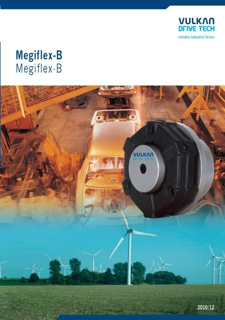
Megiflex-BMegiflex-B2010/12
GültigkeitsklauselDie vorliegende Broschüre ersetzt alle vorherigen Ausgaben, ältereDrucke verlieren ihre Gültigkeit. VULKAN ist berechtigt, aufgrundneuerer Entwicklungen die in dieser Broschüre enthaltenen Datenentsprechend anzupassen und zu verändern.Die neuen Daten gelten nur fürnach der Änderung bestellte Kupplungen.Es liegt im Verantwortungsbereichdes Anwenders dafür zu sorgen,dass ausschließlich die aktuelle Katalogversionverwendet wird. Der jeweils aktuelle Stand ist auf der Webseite vonVULKAN unter www.<strong>vulkan</strong>.com jederzeit abrufbar.Die Angaben in dieser Broschüre beziehen sich auf den technischenStandard gültig im Hause VULKAN und stehen unter den in den Erläuterungendefinierten Bedingungen. Es liegt allein im Entscheidungs- undVerantwortungsrahmen des Systemverantwort-lichen für die Antriebslinie,entsprechende Rückschlüsse auf das Systemverhalten zu ziehen.VULKAN Drehschwingungsanalysen berücksichtigen in der Regelnur das rein mechanische Schwingungsersatzsystem. Als reinerKomponentenhersteller übernimmt VULKAN mit der Analysedes Drehschwingungssystems (stationär, transient) nicht dieSystemverantwortung! Die Genauigkeit der Analyse hängt von derGenauigkeit der verwendeten bzw. der VULKAN zur Verfügunggestellten Daten ab.Änderungen aufgrund des technischen Fortschritts sind vorbehalten.Bei Unklarheiten bzw. Rückfragen kontaktieren Sie bitte VULKAN.Stand 12/2010Das Recht auf Vervielfältigung, Nachdruck und Übersetzungenbehalten wir uns vor.Maß- und Konstruktionsänderungen vorbehalten.Validity ClauseThe present catalogue shall replace all previous editions, any previousprintings shall no longer be valid. Based on new developments,VULKANreserves the right to amend and change any details contained in this cataloguerespectively. The new data shall only apply with respect to couplings thatwere ordered after said amendment or change. It shall be the responsibilityof the user to ensure that only the latest catalogue issue will beused. The respective latest issue can be seen on the website of VULKANon www.<strong>vulkan</strong>.com.The data contained in this catalogue refer to the technical standard aspresently used by VULKAN with defined conditions according to theexplanations. It shall be the sole responsibility and decision of the systemadministrator for the drive line to draw conclusions about the systembehaviour.VULKAN torsional vibration analysis usually only consider the puremechanical mass-elastic system. Being a component manufacturerexclusively, VULKAN assumes no system responsibility with the analysisof the torsional vibration system (stationary, transiently)! The accuracyof the analysis depends on the exactness of the used data and the dataVULKAN is provided with, respectively.Any changes due to the technological progress are reserved. For questionsor queries please contact VULKAN.Status: 12/2010All duplication, reprinting and translation rights are reserved.We reserve the right to modify dimensions and constructions withoutprior notice.Megiflex-B 2010/1202
InhaltIndexDie hochelastischen MEGIFLEX-B-KupplungenThe Highly Flexible MEGIFLEX-B Couplings .................................................................................................... 4Liste der Technischen Daten für MEGIFLEX-B-KupplungenList of Technical Data for MEGIFLEX-B Couplings .............................................................................................. 5 . 6KupplungsauswahlSelection of Couplings .............................................................................................................................................. 7BaureihenübersichtSummary of Series .................................................................................................................................................. 8Maßtabelle für die Baureihen 1700,1701,1710,1711,1720,1721,1740 u.1750Dimension Table for Series 1700,1701,1710,1711,1720,1721,1740 and 1750 ............................................ 9 , 10Maßtabelle für die Baureihe 1730,1731 für Dieselmotoren mit SAE-AnschlussDimension Table for Series 1730,1731 for Diesel Engines with SAE Flywheel ....................................................... 11Auslegung der MEGIFLEX-B-Kupplung in GelenkwellenausführungSelection of MEGIFLEX-B Coupling in Cardan Shaft Design ...................................................................... 12Massenträgheitsmomente/MassenMass-Moments of Inertia/Masses ....................................................................................................................13 , 14Montageanleitung für MEGIFLEX-B-KupplungenInstallation for MEGIFLEX-B Couplings .......................................................................................................... 15Hochelastische VULKAN KupplungenHighly Flexible VULKAN Couplings ...........................................................................................................16 , 17NotizenNotice .............................................................................................................................................................18 , 1903
Die Hochelastischen MEGIFLEX-B-KupplungenThe Highly Flexible MEGIFLEX-B CouplingsHochelastische VULKAN-MEGIFLEX-B-Kupplungen sind drehweiche,stoßdämpfende, allseits nachgiebige, geräuschdämpfende und elektrischisolierende Verbindungselemente,die durch ihre Baureihenvielfaltden unterschiedlichsten Anforderungen gerecht werden.Das elastische Element bietet mit seiner radialen und axialen Befestigungsmöglichkeiteine große Anzahl an Anwendungsmög-lichkeiten, vonFlanschanschlüssen über Welle-Welle-Verbindungen bis zu drehelastischenGelenkwellen.MEGIFLEX-B-Kupplungen stehen in einem Nennmomentbe-reichvon 10 Nm bis 3.125 Nm zur Verfügung. Zwei unterschiedlicheDrehfedersteifigkeiten je Baugröße ermöglichen eine Anpassungder Kupplung an die entsprechenden drehschwingungstechnischenErfordernisse.Die gegebenen technischen Daten stellen Maximalwerte dar, die nichtzeitgleich auf-treten dürfen. Die wechselseitige Beeinflussung vonBetriebszuständen führt zu einer Reduktion dieser Werte und muß beider Kupplungsauslegung berücksichtigt werden.The Highly Flexible VULKAN-MEGIFLEX-B Couplings are torsionallyflexible with an excellent multi-directional misalignment compensationcapacity. They are shock-absorbing and have good electrical isolationand noise attenuation properties. The designs available permit theinstallation of the MEGIFLEX-B in various applications.The flexible element with its axial and radial clamping feature offersa number of designs, e. g. flange/flange, shaft/shaft, cardanic shafts.MEGIFLEX-B Couplings are available in the torque range 10– 3.125Nm. With its two torsional stiffnesses/sizes, an effective tuning of theinstallation’s torsional vibra-tion behaviour may be achieved.The given technical data represent the maximum values, which maynot arise at the same time. The mutual influence of operating conditionsleads to a reduction of these values and must be considered during thecoupling selection.Megiflex-B 2010/1204Maß- und Konstruktionsänderungen vorbehalten.VULKAN reserves the right to change shapes, values and construction dimensions without prior notice.
05Megiflex-B 2010/12GrößeSizeBaugruppeDimensionGroupNenndrehmomentNorminalTorque1)TKNNm2) 4)PKV 30W3) 5) 6)C T dynNm/rad7)∆K rW7)∆KWGrad∆K ammC r dynN/mmC axialN/mmC W dynNm/GradnK max.1/min.TKmax.NmTKWNmMaximaldrehmomentMax.TorqueZul.WechseldrehmomentPerm.VibratoryTorqueZul.VerlustleistungPerm.PowerLossZul.DrehzahlPerm.RotationalSpeedZul.radialerWellenversatzPerm.Radial ShaftDisplacementRadialeFedersteifeRadialStiffnessZul.axialerWellenversatzPerm.Axial ShaftDisplacementAxialeFedersteifeAxialStiffnessZul.winkligerWellenversatzPerm. AngularShaftDisplacementWinkligeFedersteifeAngularStiffnessDynamischeDrehfedersteifeDynamicTorsional StiffnessVerhältnismäßigeDämpfungRelativeDamping0421042206210622083108321031103210411042123112321241124214311432144114421631163216411642174117422131213221412142284128421012,52025405080100120150160200220275250312,534042540050060075080010009001125140017502500312525354560757090809590110100120135170203040608012016024024036032048044066050075068010208001200120018001600240018002700280042005000750056,21012,5202540506075801001101381251561702122002503003754005004505637008751250156310000800070006500650060006000500050004000450045003600360030001,51,01,51,01,51,02,01,32,01,32,01,32,01,32,01,32,01,32,01,32,01,31,51,02,01,32,01,32,01,3130195130195435650435650870130043565011351700520780122018206509751900285025003750850130020003000356053502,01,33,02,03,02,04,02,74,02,75,03,35,03,35,03,35,03,35,03,35,03,33,02,05,03,35,03,35,03,32538152250755075170250671003405009514037055013019043065057085015022043065080011503,0°2,1°3,0°2,1°3,0°2,1°3,0°2,1°2,0°1,4°3,0°2,1°2,0°1,4°3,0°2,1°2,0°1,4°3,0°2,1°2,0°1,4°2,0°1,4°3,0°2,1°2,0°1,4°2,0°1,4°0,270,400,270,402,103,103,104,208,2011,704,306,5010,9015,606,109,1015,5022,108,2011,7022,5033,8030,9044,2014,7022,1034,6049,4061,9088,40801101602204606508201150255035501850260058508000265037006850950041005750109001530013700195001050014700244003450048750785000,750,750,750,750,750,750,750,750,750,750,750,750,750,750,75042006200830103010401230124014301440163016401740213021402840Liste der Technischen Daten für MEGIFLEX-B-KupplungenList of Technical Data for MEGIFLEX-B CouplingsMaß- und Konstruktionsänderungen vorbehalten.VULKAN reserves the right to change shapes, values and construction dimensions without prior notice.MB-LTD-2
KupplungsauswahlSelection of CouplingsDa eine Kupplungsauslegung nach DIN 740 nicht alle Betriebs-zuständeberücksichtigt, muß eine Bestätigung der Kupplungsauswahl beiVULKAN eingeholt werden.Für industrielle Anwendung sind in Anlehnung an DIN 740 folgendeAuslegungskriterien zu beachten:Due to the fact that a coupling selection according DIN 740 will notcover all application influences, any selection must be confirmed byVULKAN.The following criteria of selection for industrial application have to beconsidered with reference to DIN 740:Beanspruchung durch das NenndrehmomentDie überschlägige Auswahl der Kupplung erfolgt nach dem Nenndrehmomentder Lastseite unter Berücksichtigung der Temperatur.T KNT NST KN ≥ T N. S= zulässiges Nenndrehmoment der Kupplung= Anlagendrehmoment= Temperaturfaktor, der die Umgebungstemperatur derKupplung beim Betrieb berücksichtigtBeanspruchung durch DrehmomentstößeDas zulässige Maximaldrehmoment der Kupplung muss bei jederBetriebstemperatur mindestens so groß sein wie die im Betrieb auftretendenDrehmomentstöße unter Berücksichtigung der Stoßhäufigkeit.T K max. ≥ T S. S Z. ST K max. = Drehmoment, das als schwellende oder wechselndeBeanspruchung kurze Zeit ertragen werden kannT S = Spitzendrehmoment an der KupplungS Z = Anlauffaktor, der die Anfahrhäufigkeit Z berücksichtigtS = TemperaturfaktorSpitzendrehmoment T S:Antriebseitiger Stoß: T S = T AS · · S AJ A + J LLastseitiger Stoß: T S = T AS · · S AJ A + J LT AS = Spitzendrehmoment der AntriebsseiteT LS = Spitzendrehmoment der LastseiteJ A = Massenträgheitsmoment der AntriebsseiteJ L = Massenträgheitsmoment der LastseiteS A /S L = StoßfaktorStoßfaktor S A /S L :[Cº]–20 ≥
AbmessungenDimensionsBaureihe / Series 1700Baureihe / Series 1710Baureihe / Series 1701Baureihe / Series 1711Maße in mm / Dimensions in mmBaugruppeDimension Group042006200830103010401230124014301440163016401740213021402840Nenndreh momentNorminal TorqueTKNNm10/12,520/2540/5080/100120/150160/200220/275250/312,5340/425400/500600/750800/1000900/11251400/17502500/3125vorg.pilotbored81012121215151515202020303040max.vorg.pilotboredmax.Maß- und Konstruktionsänderungen vorbehalten.VULKAN reserves the right to change shapes, values and construction dimensions without prior notice.D 1 D 2 D 3 D 4 D 5 D 6 H 3 L 1 L 2 L 4 L 5 L 6 L 71926303838484855556565658585115812151818202020202525253030402538455555707085851001001001101101303040456060707085851001001001251251603655658080100100115115140140140160160195568510012012215015017017020020020526026034052809511511514514516516519519519525025033078810101212141416161619191926323446465656616174747088881085060648888106106116116140140136168168208111012141418182020252530,5313122,5222024282836364040505061626277242428323242424646585865707085MB-A-1700-118121720,520,523,523,5262634,534,534,545,545,56009Megiflex-B 2010/12
AbmessungenDimensionsBaureihe / Series 1720Baureihe / Series 1740Baureihe / Series 1721Baureihe / Series 1750Megiflex-B 2010/12Maße in mm / Dimensions in mm10L 8L 9L 10L 11L 12L 13L KR2N 1N 2S 2S 3S 4S 5S 6T Z T514,218,520,520,525,225,2272734,534,534,54747592444466668848887889,59,511,511,5141415,515,515,519,519,52081011161619192020252525303040788101012121414161616202020auf Anfrage unter Berücksichtigung des Diagramm auf Seite 13on request under consideration of the diagram on page 13446880100100125125140140165165165215215280242830424250505555666666808010024283042425050555566666680801006,58,58,510,510,512,512,514,514,516,516,516,520,520,520,510,213,513,516,516,518,518,521,521,524,524,524,530,530,562,5M 6M 8M 8M 10M 10M 12M 12M 14M 14M 16M 16M 16M 20M 20M 20Maß- und Konstruktionsänderungen vorbehalten.VULKAN reserves the right to change shapes, values and construction dimensions without prior notice.101414171719192222252525323232M 6M 8M 8M 10M 10M 12M 12M 14M 14M 16M 16M 16M 16M 16M 162233434343443441,51,51,51,51,51,51,51,51,51,51,51,51,51,51,5Nenndreh momentNorminal TorqueTKNNm10/12,520/2540/5080/100120/150160/200220/275250/312,5340/425400/500600/750800/1000900/11251400/17502500/3125BaugruppeDimension Group042006200830103010401230124014301440163016401740213021402840MB-A-1720-1
AbmessungenMEGIFLEX-B-Kupplungen für Dieselmotoren mit SAE-SchwungradDimensionsMEGIFLEX-B Couplings for Diesel Engines with SAE-FlywheelBaureihe / Series 1730Baureihe / Series 1731Maße in mm / Dimensions in mmBaugruppe Nenndreh momentDimension Group Norminal Torque10301230143016301640213021402840TKNNm80/100160/200250/312,5400/500600/750900/11251400/17302500/3125SchwungradFlywheelSAE6 1/ 27 1/ 26 1/ 27 1/ 288101011 1/ 2vorg.pilotboredmax.Maß- und Konstruktionsänderungen vorbehalten.VULKAN reserves the right to change shapes, values and construction dimensions without prior notice.1011 1/ 211 1/ 21411 1/ 21411 1/ 2141215152020303040D 1 D 3 D 5 D 6 H 1 H 2 L 3 L 4 L 5 L 6 L 9 L KR1 N 1 S 1 T Z384855656585851156070851001001251251601201501702002002602603401802001802002202202702703102703103104053104053104056 10 52 14 28 32 4200942222,3 96 12 62 18 36 42 6200222,3244,55099116 67244 1114 20 40 46 65510 71295,3 111010101016161919848498982525313150506262585870708888295,3 1166333,4 11295,3 1166333,4 11333,4 1180438,2 13333,4 1180438,2 1310 19 118 22,5 77 85 8333,4438,2100 11686866888888MB-A-1730-1215,9241,3215,9241,3263,5263,5314,3314,3352,4314,3352,4352,4466,7352,4466,7352,4466,711Megiflex-B 2010/12
GelenkwellenausführungCardan Shaft DesignAuslegung der Baureihe 1740Die Gelenkwellenausführung gemäß Baureihe 1740 ist geeignet für kleineund mittlere Baulängen bei einer maximalen Drehzahl von n = 1.800 min -1 .Die maximal zulässige Länge des Mittelteils ist abhängig von der Drehzahlund der Baugröße der Kupplung, eine entsprechende Kupplungsauswahlnehmen Sie bitte anhand des unten stehenden Diagramms vor.Selection of series 1740The cardan shaft design according to series 1740 is suitable for smalland medium overall lengths at a max. speed of n = 1,800 rpm. Themax. permissible length of the centre section piece depends on the speedand the size of the coupling, a corresponding coupling selection can bemade, using the below mentioned diagram.Hinsichtlich der technischen Daten ergeben sich für die hier vorliegendeReihenschaltung zweier MEGIFLEX-B-Elemente folgende Veränderungen:– der Wert CTdyn wird halbiert– die axiale Steifigkeit Caxial wird halbiertAuslegung der Baureihe 1750, Gelenkwellenausführung mitInnenlagerung.Oberhalb einer Drehzahl von n = 1.800 min -1 muß die MEGIFLEX-B-Gelenkwelle innen gelagert werden.Für eine sichere Auslegung im konkreten Einsatzfall bitten wirum Rücksprache mit dem Stammhaus.Regarding the technical data, following changes result from the presentseries connection of two MEGIFLEX-B elements:– the value CTdyn will be halved– the axial stiffness Caxial will be halvedSelection of series 1750, cardan shaft design with internal bearing.At speeds above n = 1,800 rpm the MEGIFLEX-B cardan shafthas to be internally supported.For a safe selection in a defined installation please contact VULKAN.Megiflex-B 2010/1212Maß- und Konstruktionsänderungen vorbehalten.VULKAN reserves the right to change shapes, values and construction dimensions without prior notice.
Massenträgheitsmomente/MassenMass-Moments of Inertia/Masses2 12 12121Baureihe / Series 1720Baureihe / Series 1721Baureihe / Series 1730Baureihe / Series 1731Megiflex-B 2010/12BaugruppeDimension Group14042006200830103010401230124014301440163016401740213021402840TKNNm10/12,520/2540/5080/100120/150160/200220/275250/312,5340/425400/500600/750800/1000900/11251400/17502500/3125J = Massenträgheitsmoment / Mass moment of inertia kgm 2 x 10 -4Baureihe /Series 1720Baureihe /Series 1721Maß- und Konstruktionsänderungen vorbehalten.VULKAN reserves the right to change shapes, values and construction dimensions without prior notice.m = Masse / Mass kgJ 1 J 2 m 1 m 2 m ges. J 1 J 2 m 1 m 2 m ges. SAE J 1 J 2 SAE m 1 m 2 m ges.1,05,611,631,8534,293,196,2179,6185,7419,9427,5457,31275136339310,371,503,329,9911,326,329,456,462,5125,4133,1144,3448,653617680,310,811,182,332,404,364,436,326,4010,7811,0111,5219,4219,7836,10,160,370,501,151,201,921,982,993,114,955,185,509,589,9020,30,471,181,683,483,606,286,419,319,5115,7316,1917,0229,029,6856,41,096,012,6634,3737,7100,2105,8193203,5448,5466,45071375148641850,371,53,329,9911,326,329,456,462,5125,5133,1144,3448,653617680,320,851,252,432,544,554,676,596,8011,2111,5812,2420,2820,937,50,160,370,501,151,201,921,982,993,114,955,185,509,589,9020,350,181,641,753,583,746,476,659,589,9116,1616,7617,7329,8630,8057,9---6 1/ 27 1/ 2-6 1/ 27 1/ 28-810---137,6208,8-165,01244,23263,61---9,99-26,2622---6 1/ 27 1/ 2-6 1/ 27 1/ 28---2,633,24-3,1453,8464,062---1,15-1,919---3,784,395,065,775,9810 1067,6711 1/ 2 1674,47 125,54 10 9,154 14,104,94911 1/ 2 11,561 16,5110 108510 9,528133,111 1/ 2 169211 1/ 2 11,935 5,18 14,7117,12- - - - - - -11 1/ 2 212011 1/ 2 14,023,6448,69,6014 572414 23,433,011 1/ 2 223211 1/ 2 14,624,55369,9014 583614 24,033,911 1/ 214-308,9948,429896593-56,361768-81011 1/ 214-4,538,1015,625,0-2,9920,35-7,5211,09- - - - - - --36,045,4MB-M-1720-1
Montageanleitung für MEGIFLEX-B-KupplungenInstallation for MEGIFLEX-B CouplingsBei Einbau bitte beachten!Montage der MEGIFLEX-B mit Schraubverbindung:Die Kupplungsnabe auf die Welle ziehen und den Anschlußflansch an dasSchwungrad montieren. Das elastische Element zunächst mit den axialenBefestigungsschrauben an die Flanschnabe oder das Schwungrad befestigen. Imnächsten Arbeitsgang die Kupplungsnabe im elastischen Element platzieren.Durch Anziehen der radialen Befestigungsschrauben wird die Nabe befestigtund gleichzeitig eine Druckvorspannung im Element erzeugt.Montage der MEGIFLEX-B mit Steckverbindung:Die Kupplungsnabe auf die Welle ziehen und den Anschlußflansch an dasSchwungrad montieren. Die axialen Steckbolzen für das elastische Elementmüssen zunächst an die Flanschnabe oder das Schwungrad montiert werden.Die gummifreie Fläche des axialen Aluteils zum Schwungrad bzw. zurFlanschnabe hin anordnen und mit den radialen Befestigungsschrauben aufdie zylindrische Nabe montieren.Für problemloses Gleiten der Steckbolzen müssen die axialen Bohrungen imelastischen Element vor dem Zusammenschieben der Aggregate gut eingefettetwerden. Es ist darauf zu achten, daß keine Fettrückstände auf den gummiertenFlächen zurückbleiben. Die Kupplung kann dann durch leichten axialen Druckauf die Steckbolzen aufgeschoben werden.Beim Anziehen der Schrauben unbedingtdarauf achten, daß die ein<strong>vulkan</strong>isierten Aluminiumteile nicht im elastischenMEGIFLEX-B-Element verdreht werden.Ein besonderes Augenmerk ist hierbei auf denrichtigen Kontakt der zylindrischen Flächen zwischen Aluteil und Nabe zu richten.Gegebenenfalls wird ein Verdrehen des Gummikörpers mittels eines geeignetenWerkzeuges verhindert. In jedem Fall empfehlen wir, eine kleine Menge Fett unterjeden Schraubenkopf zu geben, um die Reibkräfte entsprechend herabzusetzen.MEGIFLEX-B-Kupplungen werden mit selbstsichernden Schrauben geliefert, diedurch einen farbigen 2-Komponenten-Kleber auf dem Gewinde gekennzeichnetsind. Die Besonderheit besteht darin, daß der Klebstoff in winzigen kleinenKügelchen – sogenannte Mikrokapseln – eingeschlossen ist. Während desEinschraubens platzen die Kapseln auf, der Klebstoff benetzt SchraubenundMuttergewinde und härtet aus.Die Verbindung ist nach dem Aushärten des Klebstoffesdauerhaft mit einer Temperaturbeständigkeit bis +120°C gesichert. Die Aushärtezeitbis zur vollen Funktionsfähigkeit der Schraubensicherung beträgt 24 Stundenbei +20°C oder 15 Minuten bei +70°C (Erwärmung durch Warmluftgebläse).In jedemFall soll bei Raumtemperatur eine Aushärtezeit von 5 Stunden bis zur Inbetriebnahmeder Kupplung nicht unterschritten werden. Die selbstsichernden Schraubenkönnen maximal 3mal verwendet werden.Grundsätzliche Montagehinweise:Der Anzug der radialen und je nach Ausführung axialen Schrauben sollte in ca.3 Umläufen erfolgen. Erste Voraussetzung für einen fehlerfreien späteren Betrieb derKupplung ist das Anziehen sämtlicher Schrauben mit einem Drehmomentschlüsselauf das erforderliche Drehmoment (siehe Tabelle der Anzugsmomente). BeiNichtbeachtung dieser Vorschrift geht die Vorspannung der Schrauben unterdynamischer Beanspruchung der Kupplung bereits nach wenigen Lastwechselnverloren. Die Folge ist: Die Schrauben lösen sich und die Kupplung wird zerstört.Please note the following during the installation!Assembly of the MEGIFLEX-B coupling with screw connection:Push the coupling hub onto the shaft and install the connection flange at the flywheel.The flexible element is fixed using the axial fastening screws at the flangedhub or flywheel. The next procedure is to place the coupling hub into the flexibleelement. Tightening the radial fastening screws, fixes the hub, and simultaneouslya prestress in the element is produced.Assembly of the MEGIFLEX-B coupling with plug connection:Push the coupling hub onto the shaft and install the connection flange at the flywheel.Now install the axial socket pins for the flexible element at the flanged hubor flywheel. Arrange the rubber-free surface of the axial aluminium part to theflywheel and to the flanged hub resp. and install it with the radial fastening screwson the cylindrical hub.The axial bores in the flexible element have to be well greased before the aggregatesare pushed together to ensure that the socket pins can slide without problems.So it is to see to it that no fat residues will be left on the rubber coated surfaces.The coupling can then be pushed onto the socket pins through a slight axialpressure. During the tightening of the screws please take absolutely care that thealuminium parts, that are vulcanized in the rubber element, are not twisted in theflexible MEGIFLEX-B element.In this case please pay special attention to the proper contact of the cylindricalsurfaces between the aluminium part and the hub. If necessary, twisting of therubber part has to be prevented by means of an appropriate tool.In any case we recommend to give a little bit grease under each screwhead toreduce the frictional forces accordingly.MEGIFLEX-B couplings are supplied with self-locking screws that are marked witha coloured 2-component-adhesive on the thread.The special feature is that the adhesive is enclosed in small capsules, so-calledmicro-capsules. When the screws are screwed in, the capsules burst, thereby theadhesive wets the screws and the internal screw thread and then hardens. Theconnection is permanently secured with a temperature stability up to +120°Cafter the adhesive has hardened. The hardening time – until the full operativenessof the screw locking has been achieved – is 24 hours at +20°C or 15 minutesat +70°C (heating through a hot-air blower). Before putting into operation, ahardening time, at ambient temperature, of at least 5 hours, is recommended. Theself-locking screws can be used for a maximum of 3 times.Basic assembly instructions:The taper of the radial bolts – and according to the execution axial bolts – shouldhappen in approximately 3 (three) circulations. The first condition for a troublefreefuture operation of the coupling is that all screws have to be tightened with atorque spanner to the necessary torque (see table of the tightening torques).If this instruction is not carried out, the prestress of the screws under dynamicstress of the coupling, is, already after few load cycles, no more available.The result is: The screws loosen and the coupling is destroyed.MEGIFLEX-BSchraube / ScrewAnzugsmoment / Tightening torqueGröße / SizeDIN 912NmTabelle der Anzugsmomente / Table of Tightening Torques0420M 61006200830M 825Maß- und Konstruktionsänderungen vorbehalten.VULKAN reserves the right to change shapes, values and construction dimensions without prior notice.10301040M 105012301240M 128614301440M 14135163016401740M 1621521302140M 204102840M 2041015Megiflex-B 2010/12
Hochelastische VULKAN KupplungenHighly Flexible VULKAN CouplingsVULKARDAN-EVULKARDAN-EVULASTIK-L für GlockeneinbautenfreistehendTORFLEX TORFLEX-HTbell-housingfree-standingDie hochelastische VULASTIK-L-Kupplung ist aufgrund ihrerSteckbarkeit überwiegend bei Glockeneinbauten im Einsatz. DieAnschlußabmessungen sind entsprechend der DIN 6281 und derSAE-Norm.Drehmomentbereich: 0,4 - 40 kNmLieferbar in Gummi- oder Silikonausführung.Die hochelastische VULKARDAN-E Kupplung wird verwendet, um dasDrehschwingungsverhalten von Antriebsanlagen optimal abzustimmen.Durch ihre steckbare Ausführung fi ndet sie vornehmlich Anwendungin sogenannten Glockeneinbauten.Drehmomentbereich: 0,16 - 5 kNmLieferbar in Gummi- oder Silikonausführung.Die hochelastische VUKARDAN-E Kupplung (freistehend) fi ndetVerwendung bei der Verbindung von elastisch/starr aufgestelltenMotoren mit Getrieben oder anderen Arbeitsmaschinen. Sie ergänztdie Kupplungen der RATO-Serie im unteren Drehmomentbereich.Drehmomentbereich: 1,6 - 20 kNmLieferbar in Gummi- oder Silikonausführung.Die elastische TORFLEX-Kupplung mit progressiver Drehsteifi gkeitwurde speziell zur Geräuschverhinderung in Bootsantrieben konstruiert.Drehmomentbereich: 0,25 - 1,6 kNmLieferbar in Silikon.Für größere Leistungsbereiche bzw. härtere Einsatzfälle ist dieTORFLEX-HT geeignet.Drehmomentbereich: 2,0 - 15 kNmLieferbar in Gummi.The highly fl exible VULASTIK-L couplings are with „slip-on“ featuresand therefore they are provided mainly for installation inflanged belltypeconnections. The installation dimensions correspond to DIN6281 and SAE standards.Torque range: 0.4 - 40.0 kNmAvailable in both rubber and silicone.The highly flexible VULKARDAN-E coupling is used to tune the torsionalresponse of the system. It is a coupling with „slip-on“ feature and thereforeis mainly used in bell-housing installations.Torque range: 0.16 - 5.0 kNmAvailable in both rubber and silicone.The highly fl exible VULKARDAN-E free-standing coupling is used to connectflexibly/rigidly mounted engines with gearboxes or another machinery. Itcompletes the RATO Family in the lower torque range.Torque range: 1.6 - 20.0 kNmAvailable in both rubber and silicone.The flexible TORFLEX coupling with a progressive torsional stiffnessspecially designed to combat gearnoise in boat reverse/reduction gearboxes.Torque range: 0.25 - 1.6 kNmAvailable in silicone.For higher torques and heavy duty applications our TORFLEX-HTis suitable.Torque range: 2,0 - 15 kNmAvailable in rubber.Megiflex-B 2010/1216Maß- und Konstruktionsänderungen vorbehalten.VULKAN reserves the right to change shapes, values and construction dimensions without prior notice.
Hochelastische VULKAN KupplungenHighly Flexible VULKAN CouplingsMEGIFLEX-B VULKARDAN-L VULKARDAN-PAnfl anschaußenlager/Integral Shaft SupportDie hochelastische MEGIFLEX-B-Kupplung ist in alle Richtungennachgiebig. Sie wird als Flansch-Welle- oder Welle-Welle-Verbindungeingesetzt.Drehmomentbereich: 0,01 - 3,15 kNmLieferbar in Gummi- oder Silikonausführung.VULKARDAN-LVorschaltkupplung mit linearer Drehsteifi gkeit.Drehmomentbereich: 0.16-12.5 kNmVULKARDAN-PVorschaltkupplung mit progressiver Drehsteifi gkeit.Drehmomentbereich: 0.32-31.5 kNmAnfl anschaußenlagermit hochelastischer KupplungDiese Ausführung wird bei Antriebsanlagen mit hohem Beugewinkelder Gelenkwelle verwendet. Die durch die Gelenkwelle entstehendenReaktionskräfte werden durch das Anfl anschaußenlager aufgenommenund reduzieren somit die Kurbelwellenbeanspruchung.Drehmomentbereich: 0,63 - 25 kNmThe highly flexible MEGIFLEX-B couplings are flexible in all directions.They are used to connect flywheel to shaft as well as shaft to shaft.Torque range: 0.01 - 3.15 kNmAvailable in both rubber and silicone.VULKARDAN-LIntermediate coupling with linear torsional stiffness.Torque range: 0.16 - 12.5 kNmVULKARDAN-PIntermediate coupling with progressive torsional stiffness.Torque range: 0.32 - 31.5 kNmIntegral Shaft Supportwith highly flexible couplingThis design will be fitted in installations where the cardan shaft hasa large angle of inclination. The resulting lateral and axial reactionforces from the cardan shaft are supported by the bell-housing soreducing the engine crankshaft loading.Torque range: 0.63 - 25.0 kNmMaß- und Konstruktionsänderungen vorbehalten.VULKAN reserves the right to change shapes, values and construction dimensions without prior notice.17Megiflex-B 2010/12
NotizenNoticeMegiflex-B 2010/1218
NotizenNotice19Megiflex-B 2010/12
BrazilVULKAN do Brasil Ltda.Rod. Engº Constancio Cintra, km 91Bairro da Ponte – Cx Postal 141CEP 13252-200 Itatiba, São Paulo/BrasilTel. +55 11 4894-7300 · Fax +55 11 4894-7329E-Mail: <strong>vulkan</strong>@<strong>vulkan</strong>.com.brGermanyVULKAN Kupplungs- undGetriebebau GmbH & Co. KGHeerstr. 6644653 Herne/GermanyTel. +49 2325 922-0 · Fax +49 2325 71110E-Mail: info.vkg@<strong>vulkan</strong>.comKoreaVULKAN Korea Co.4th floor, Samsung Haeundae Bldg.1153-8, Jung 1-Dong, Haundae-GuBusan 612-847,KoreaTel. +82 51 2562473 ˆ Fax +82 51 2562474E-Mail: kim-namseol@<strong>vulkan</strong>-korea.co.krSpainVULKAN Española S.A.Polig. Ind. MoscatelaresAvda. Montes de Oca, 19, Nave 728709 S.S. Reyes, Madrid/SpainTel. +34 91 3590971/72 · Fax +34 91 3453182E-Mail: <strong>vulkan</strong>@<strong>vulkan</strong>.esChinaWuxi VULKAN Technologies Co. Ltd.Xinzhou Road, Lot 93D-3 in Wuxi Science & TechnologyIndustrial Park, 214028 Jiangsu Prov. P.R. ChinaTel. +86 510 8534 2222 ˆ Fax +86 510 8534 2345E-Mail: service@<strong>vulkan</strong>china.comIndiaVulkan Technologies Pvt LtdS.No.539-B ,Kasar Amboli ,Tal.MulshiPirangut Industrial Area .GhotawadeDist Pune -412111 - IndiaTel. -[91-20 ] 66765526 - Fax -[91-20] 66765551E-mail: info@<strong>vulkan</strong>india.comNetherlands, Belgium, LuxembourgVULKAN BeneluxVan Coulsterweg 32952 CB Alblasserdam / NetherlandsTel. + 31 (0) 78 68 107 80 – Fax +31 (0) 78 68 107 99E-Mail: info@<strong>vulkan</strong>-benelux.comUnited KingdomVULKAN Industries LTDArcher RoadArmytage Road Industrial Estate,Brighouse, W.-Yorkshire, HD6 1XF/GBTel. +44 1484 712273 - Fax +44 1484 711376E-Mail: info@<strong>vulkan</strong>.co.ukFranceVULKAN France SA12, avenue Émile ZolaZA de l'Agavon13170 Les Pennes Mirabeau/FranceTel. +33 04 42 02 21 01 . Fax +33 04 42 02 21 09E-Mail: krabba@<strong>vulkan</strong>.frItalyVULKAN Italia S.R.L.Via dell´ Agricoltura 2P. O. Box 315067 Novi Ligure (AL)/ItalyTel. +39 0143 310211 · Fax +39 0143 329740E-Mail: info@<strong>vulkan</strong>-italia.itSouth AfricaVULKAN South AfricaUnit H6 Pinelands Office ParkArdeer RoadModderfontein,EdenvaleJohannesburg, South AfricaTel: +27 11-6084044 - Fax: +27 11-6081877E-Mail: infro@<strong>vulkan</strong>sa.co.zaU.S.A.American VULKAN Corporation2525 Dundee RoadWinter Haven,Florida 33884/USATel. +1 863 3242424 · Fax +1 863 3244008E-Mail: <strong>vulkan</strong>usa@<strong>vulkan</strong>usa.comwww.<strong>vulkan</strong>drivetech.com


