Create successful ePaper yourself
Turn your PDF publications into a flip-book with our unique Google optimized e-Paper software.
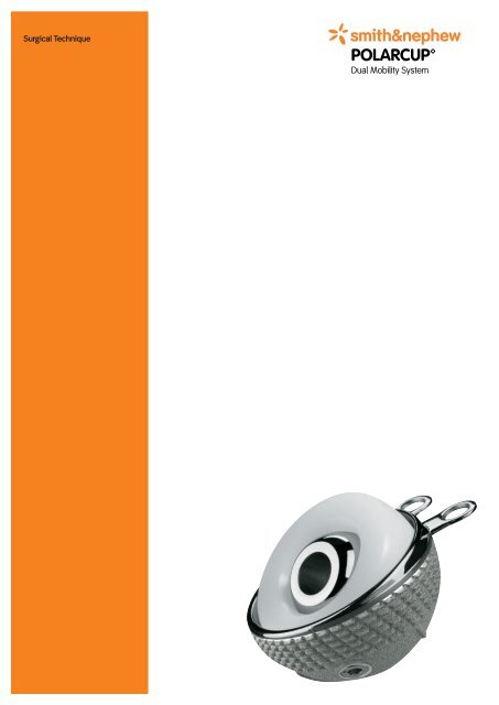
POLARCUPTable of ContentsIntroduction ........................................................................... 3Indications ............................................................................ 5Contraindications .................................................................. 5Case Studies ......................................................................... 6Preoperative Planning ............................................................7<strong>Surgical</strong> <strong>Technique</strong> ................................................................ 8Postoperative Treatment ......................................................18References ...........................................................................18Sterilization ..........................................................................19Implants .............................................................................. 20Instrumentation ................................................................... 22Nota BeneThe technique description herein is made available to the healthcare professionalto illustrate the authors’ suggested treatment for the uncomplicated procedure.In the final analysis, the preferred treatment is that which addresses the needs ofthe patient.1
IntroductionWith the introduction of the low-friction arthroplasty, Sir JohnCharnley opened a new era in total hip replacement.Its success was however balanced by long-term looseningdue to polyethylene wear and also by a high rate of dislocationassociated with the use of 22mm heads.Prof. Bousquet together with the medical school of SaintEtienne, France, offered an answer to dislocation with a constraintinlay moving freely in a thin, inside polished metallicshell. This “dual mobility” principle consists in joining theadvantages of low friction with those of extended ball-headsizes.Compared to other cup systems, the concept offers an extremelylow dislocation rate for primary hip replacement aswell as for revision situations (e.g. repetitive dislocations.)Small becomes bigThe diameter of the joint becomes the inlay’s diameter (example:Ø 37 mm for a 43 mm cup and Ø 61 mm for 67 mmcup) – resulting in a high head-neck-ratio and significantlyincreased R.O.M. compared to standard cup systems. Thisalso explains the low rate of dislocations: 0.1% (Leclercq,Aubriot, 1995); 0.7% (Fiquet, Noyer, 2006).The two articulations are never moving at the same time.The large articulation takes over from the small only whenthe stem’s neck comes into contact with the inlay. Thisoccurs when a large range of motion is required – e.g. whileclimbing stairs (cf. Adam, Fessy 2000, 2005).3
Mechanism avoids inlays overstress and preservesbone anchorageThe POLARCUP components issued from the original Bousquetconcept, completed with the POLARSTEM product portfolioresult in a complementary system designed to face the“three components articulation”, in order to reduce polyethylenewear, and, due to its versatility, preoperatively allowa variety of anchoring options avoiding migration of polyethylenewear.1. Cup on inlay2. Inlay on head3. Stem neck on inlay edgeFirst considered as a curiosity, the principle has demonstratedits proved advantages with a follow-up of more than 30 years.Both, POLARCUP and POLARSTEM represent the third gene r-ation of implants, and with their well adapted instrumentssummarise the know-how and the wishes of the backing upsurgeons GROUPE GILES.4
Indications• All forms of osteoarthritis• Dislocation risks• Progressive loss of function of the hip joint as a result of a degenerativepost-traumatic or inflammatory/rheumatic destruction of the joint• Femoral head necrosis• Proximal femoral fractures (especially femoral neck)• Status following earlier operations such as osteosynthesis,intertrochanteric osteotomies, arthrodesis or failed joint replacement• Neurological diseasesContraindications• Acute or chronic infections, local or systemic• Severe damage to muscles, nerves or vessels that are a risk to the affected extremity• Associated disorders that could interfere with the functioning of the implant5
Case StudiesPreoperativePostoperative70 years, female patient withdysplastic hip.POLARCUP with two pegs and onescrew.Postoperative71 years, POLARCUP with flangesremoved in a male patient withcoxarthrosis.6
Preoperative PlanningX-ray templates (scale 1.15, Lit. No. 1571) are available for preoperative planning and allow to plan• the intended size of the implant• the cup’s best position regarding acetabular geometryNoteExact determination of the shell size preoperatively using radiographic templates is onlypossible to a certain extend.The correct shell size is finally judged on the basis of the definitive reamer size and dimensionallyaccurate trial shell.7
<strong>Surgical</strong> <strong>Technique</strong>Position of patient and approachSurgery is performed with the patient in anextended supine or lateral position.<strong>Surgical</strong> approach – lateral or dorso lateral –is determined on the basis of the patientdata established in advance and preferenceof the surgeon.Removal of the femoral headAn osteotomy of the femoral neck is performedin accordance with the preoperativeplanning for the corresponding stem system.NoteIt is highly recommended to use stems withpolished necks, and avoid use of skirtedheads (XL or XXL size only to be used inexceptional cases) and stem tapers with extractionholes so that there is no impingementwith PE Inlay.Preparation of the acetabulumThe joint capsule is opened and sufficientlyresected, fully if necessary.The acetabulum is exposed to allow a goodview and sufficient room for reaming instruments.Osteophytes must be removed from the acetabularrim and fossa.Acetabular cavity is cleaned and hemostasiaachieved.8
Assembly of the reamer andorientation guideThe reamer is placed on the drive shaft usingpressure and turned clockwise until the lockingmechanism snaps in.The orientation guide may be used for purposesrelative to the cup position, whichideally is 10–20° anteversion and 40–50°inclination.Rod should be perpendicular to the coronalplane and rod is perpendicular to thesagittal plane of the patient. If the patient islying in supine position (see illustration,showing a left hip) the long edge of the tablecan be used for orientation.Reaming of the acetabulumThe acetabulum is reamed horizontally comparedto the patient’s positioning using aspherical original Plus reamer. Start with thesmallest size to reach the true acetabularfloor.Reaming is continued using increased diameters(2 mm increments) and respecting finalanteversion and inclination until the cartilagelayer is fully removed and the subchondralbone bleeds uniformly.NoteFor head fractures a reamer size equal to – or2 mm smaller than – the head size could beused to start. Then reaming is continued downto the base of fovea actebuli (teardrop figure).Excessive reaming of the periphery should atall times be avoided as this would result ina level of bone loss, especially at the anteriorand posterior columns of the acetabulum,that is too high.Bone slurry remaining in the last reamer canbe used to fill in the acetabulum.9
Trial cup testAfter the preparation of the acetabular cavity,a trial cup of the same size as the lastreamer used, is screwed on the trial shellhandle. Over the whole POLARCUP range,the corresponding implant is oversized by0.7 mm: a POLARCUP Ø 53 mm truly measures53.7 mm.The trial cup is impacted in the reamedace tabulum, the 6° skirt positioned superiorposterior respecting 10–20° anteversionand 40–50° inclination. The orientation guidecan be clipped on the handle.When using the POLARCUP with flanges, these can also be used as guides for positioning.For example for a right hip, the right flange should be positioned at 12 o’clock.This trial cup must:• have a good primary stability• be tight fitted into the cavity on its complete circumferenceIf the trial handle does not keep initial position, depending on cup version used (with or withoutflanges and pegs), either intra and/or peripherical anchorages can be added (screwswith or without pegs) or a bigger diameter can be chosen. If millimetre reamers are available,the following reamer can be used which will allow 1.7 mm press-fit, or 2.7 mm if no furtherreaming is done.10
Trial with inlayAfter removing trial cup handle, a trial inlay isinserted so that length stability and leg lengthtests can be performed using trial headseither on femoral rasp or on implant if femoralpreparation was done first.NoteIf the trial handle once impacted does notmove, the press-fit of the same size of thedefinitive implant will be perfect. If a versionwith pegs and flanges is being used, flangescan be broken off and no additional screwswill be needed.If a POLARCUP version with pegs and flanges is being used, the 2 marks on trial cupindicate the flanges’ position.Depending on primary stability of the trial cup, bone quality of the acetabular cavity andsurgical practice, different versions of the POLARCUP can be implanted:• without additional fixation (version with no pegs and flanges, or flanges broken off)• with peri-acetabular fixation (use of screws through flanges)• with peri- and intra-acetabular stabilisation (use of pegs and screws)The preparation of the acetabular cavity, cup positioning and impaction is exactly the samein all cases.11
Implantation of a POLARCUP withoutflanges and pegsImplant is impacted using handle mountedwith shell holder corresponding to implantsize. The shell holder is composed of severalseparate parts to allow good cleaning aftersurgery and each one can be used for severalsizes. To easily screw the base plate on thehandle, the handle is screwed directly on theshell holder in the sterilisation tray. The implantis then mounted on the shell holderand handle screwed until cup is solidly maintained.An alignment guide may be used for orientationpurposes relative to the cup position.The assembled alignment guide can beclipped on the handle to assure good orientation.The cup is introduced with the 6° skirt positionedsuperior posterior and seating outsidethe acetabular cavity to avoid dislocations inhigh risk cases, and impacted using ahammer.The shell holder is then unscrewed andremoved.Implantation of a POLARCUP with flangesand pegsThis cup type can be used in several ways:• As a standard press-fit cup: Break off flanges(pre- or peroperatively) or bend them aroundthe upper acetabular rim• When peri-acetabular fixation is needed:Use 1 or 2 screws through flanges• When peri- and intra-acetabular stability isequired: Use 2 pegs and 1 or 2 screwsthrough flanges12
Cutting or bending flangesFlanges can be easily broken off using theflange cutter. Flange is inserted inside thecutter’s extremity and then bended up anddown 3–4 times. The flange will automaticallybreak. Flange breaking can be decidedpreoperatively if good primary stability isverified using the trial cup.It can also be decided to break off flanges after cup impaction or bend them around theupper acetabular rim, which also allows their use as positioning guides. For example for aright hip, the right flange should be positioned at 12 o’clock.When the flanges contact the upper rim, the cup is well positioned and the 6° skirt iscorrectly positioned outside the acetabular cavity.Abschneiden oder Biegen der FlanscheFlanges are then broken in situ using theflange cutter or bended around the upper acetabularrim using a small metallic impactor.In both cases, the impactor is placed insidethe cup to solidly maintain it, avoid tilting andall micromovements that could reduce primarypress-fit stability.13
Peri-acetabular fixation using screws(through flanges)The implant will be introduced and impactedusing the shell holder in the prepared acetabulumas described, and flanges are curvedaround the acetabular rim using a smallmetallic impactor.Holes are drilled through flanges using theØ 3.5 mm drill. Screw length can be determinedusing the depth gauge. Stability isstrengthened with the use of Ø 4.5 mm corticalscrews introduced divergently throughthe flange holes, in the acetabular rim.Important noteScrews can be used solely through flanges excluding the use of pegs. Pegs cannot be replacedby screws.The contrary is not possible: Pegs are impacted and not screwed and must always be usedwith at least 1 screw.Peri- and intra-acetabular stabilisationusing 2 pegs and 1 or 2 screwsIn the case of insufficient stability of the trialcup, it is also possible to use screws andpegs to assure primary stability of the implant.Pegs: Following the unscrewing directionindicated on the plug unscrew the obturatingplugs using the special T-Handle. Theimplant will then be introduced and impactedusing handle and shell holder in the preparedacetabular cavity as already described.NoteIt is very important to unscrew plugs in directionindicated by the engraved arrow. Turnedthe wrong way, the plugs could jam. Onceplugs unscrewed, pegs have to be used. It isnot possible to replace the plugs once theyhave been taken off.14
Periacetabulare Fixierung mit Schrauben(durch Flansche)The first hole is drilled using the Ø 6 mmflexible drill and drill guide. The first pegis mounted on the self-holding peg impactorand impacted in the ischium or pubis archusing a hammer and the straight or curved pegimpactor.Periacetabulare Fixierung mit SchraubenThe peg impactors’ extremities are speciallydesigned to fit in the peg hole and tobe stopped once the peg is fully seated.The second hole is then prepared and theprocedure replicated.Fixation is completed by bending flangesand using screws with the impactor insidethe cup as described in the peri-acetabularfixation paragraph.NotePegs must be used by 2 and also with at least1 screw through a flange allowing a 3-pointfixation and avoiding tilting.However, if fixation is not optimally achieved,it may be necessary to choose another cupsize than initially planned. In presence of poorquality or if the surface presents some peripheralor superior pole bone loss, impact ingthe following size could improve primary stability.This has to be decided during surgery.15
It is recommended to always finish impaction of the first peg before starting to drill thehole for the second one, though the cup’s positioning can slightly change after impaction.It is also recommended to start with the impaction of the 2 pegs before screwing throughflanges. Pegs are delivered per 2 in one box.Placement of the PE inlayThe PE inlay, corresponding to the impactedcup size is seized with the femoral headusing the head-inlay inserter.Therefore the inlay is placed on the supportingplastic as well as the ball head (metal orceramic) is put on the inlay’s opening. Theupper plastic bit is pushed down to seizethem.T-Handle is then turned until the head is fullylocked inside the inlay and moves freely.It is recommended to position the upperthreaded part of the instrument as low aspossible (metallic part laying on handle)and no threads apparent under metallic partand plastic extremity.If inlay and ball head have to be seized in situ(e.g. revision of a monobloc stem) the sameinstrument is used after changing plastic spareparts. The inserter is than fitted on themonobloc stem’s neck, the inlay being placedon the femoral ball head and the T-Handleturned until the head is fully locked insidethe inlay and moves freely.16
Femoral ball head is impacted on stem’staper neck. The “head and inlay” assembly isthen reduced into the cup.NoteWhile introducing the inlay make sure that nosoft tissues bother the contact between theinlay and the cup.An airless noise will be heard when the headis fully impacted in the inlay.Sometimes locking of the inlay on a monoblocstem in situ can be difficult.It could be helpful to leave the inlay in sterilewarm water for a few minutes.It is highly recommended to use stems withpolished necks, and avoid use of skirtedfemoral ball heads.17
Postoperative TreatmentPost-op follow-up is conducted according to the femoral component type – cemented ornon-cemented.In a general manner leg discharge should be short. Early total weight bearing – respectivelypartial with two crouches during the first six weeks – is permitted in case of satisfying followup.According to the patient’s status, postoperative treatment and duration are selected undersurgeon’s responsibility.ReferencesLeclercq S, El Blidi S, Aubriot JH (Caen)“Bousquet’s prosthesis for recurrent total hip dislocation”Revue de Chirurgie Orthopédique (RCO) 1005, 81, 389–394Beguin L, Adam PH, Farizon F, Fessy MH (St Etienne)“Total Hip Arthroplasty: Treatment of Chronic Instability using a double-mobility cup”JBJS (BR) 2002; 84-B SUPPFiquet A, Noyer D“Polarsystem” dual mobility hip prostheses and “minimally invasive surgery” (MIS)Springer 2006 Interactive surgery (2006) 22: 1–5Adam P, Farizon F, Fessy MH CHU Bellevue (St Etienne)“Dual articulation retentive acetabular Inlays and wear: surface analysis of 40 retrievedpolyethylene implants”Revue de Chirurgie Orthopédique 2005, 91, 627–636Philippot R (St Etienne)“Survival of Dual mobility socket after 10 years follow up”Poster EFFORT, LISBON June 2005Aubriot JH, Lesimple P, Leclercq SEtude du cotyle non scellé de Bousquet dans cent prothèses totales de hanche hybrides(composant fémoral type Charnley scellé). Recul moyen 5 ans.Acta Orthopaedica Belgica, Vol 59 Suppl.I.–1993Farizon F, De Lavison R, Auzoulai JJ, Bousquet GResults with a cementless alumina coated cup with a dual mobility, a twelve yearsfollow-up study.International Orthopaedics (SICOT) (1998), 22: 219–22418
SterilizationImplantsAll the implants described in this <strong>Surgical</strong> <strong>Technique</strong> are sterile when they are delivered bythe manufacturer. Re-sterilization is not allowed.InstrumentsSystem components and instruments are not sterile when they are delivered. Before use theymust be cleaned by the usual methods in accordance with internal hospital regulations andsterilized in an autoclave in accordance with the legal regulations and guidelines applicablein the relevant country. (For detailed information please refer to leaflet Lit. No. 1363.)The correct settings are given in the instructions for use issued by the autoclave manufacturer.Instrument manufacturers and dealers accept no responsibility for sterilization of products bythe customer.19
ImplantsShellsTi-Plasma coatedwith Pegs and FlangesoldArt. No. Art.No. Size / Ø11000476 ORPCTI43 4311000477 ORPCTI45 4511000478 ORPCTI47 4711000479 ORPCTI49 4911000480 ORPCTI51 5111000481 ORPCTI53 5311000482 ORPCTI55 5511000483 ORPCTI57 5711000484 ORPCTI59 5911000485 ORPCTI61 6111000486 ORPCTI63 6311000487 ORPCTI65 6511000488 ORPCTI67 67HA coatedwith Pegs and FlangesoldArt. No. Art.No. Size / ØORPC43 43ORPC45 45ORPC47 47ORPC49 49ORPC51 51ORPC53 53ORPC55 55ORPC57 57ORPC59 59ORPC61 61ORPC63 63ORPC65 65ORPC67 67Ti-Plasma coatedoldArt. No. Art.No. Size / Ø11000489 ORSPC43 4311000490 ORSPC45 4511000491 ORSPC47 4711000492 ORSPC49 4911000493 ORSPC51 5111000494 ORSPC53 5311000495 ORSPC55 5511000496 ORSPC57 5711000497 ORSPC59 5911000498 ORSPC61 6111000499 ORSPC63 6311000500 ORSPC65 6511000501 ORSPC67 67Uncoatet polished StainlessSteel (for use with Cement)oldArt. No. Art.No. Size / Ø11000502 CSPC43 4311000503 CSPC45 4511000504 CSPC47 4711000505 CSPC49 4911000506 CSPC51 5111000507 CSPC53 5311000508 CSPC55 5511000509 CSPC57 5711000510 CSPC59 5911000511 CSPC61 6111000512 CSPC63 6320
PE InsertsoldArt. No. Art. No. Ø Size11000515 ML4322 22 mm 4311000516 ML4522 22 mm 4511000517 ML4722 22 mm 4711000518 ML4922 22 mm 4911000519 ML5122 22 mm 5111000520 ML5322 22 mm 5311000521 ML5522 22 mm 5511000522 ML5722 22 mm 5711000523 ML5922 22 mm 5911000524 ML6122 22 mm 6111000525 ML6322 22 mm 6311000526 ML6522 22 mm 6511000527 ML6722 22 mm 67oldArt. No. Art. No. Ø SizeML 4328 28 mmML 4528 28 mm11000528 ML4728 28 mm 4711000529 ML4928 28 mm 4911000530 ML5128 28 mm 5111000531 ML5328 28 mm 5311000532 ML5528 28 mm 5511000533 ML5728 28 mm 5711000534 ML5928 28 mm 5911000535 ML6128 28 mm 6111000536 ML6328 28 mm 6311000537 ML6528 28 mm 6511000538 ML6728 28 mm 67PegsArt. No. old Art. No. Length11000539 02CPAMX2 (2 per box) 43Cortical ScrewsArt. No. old Art. No. Ø Length11000540 CT45040YT 4.5 mm 40 mm11000541 CT45044YT 4.5 mm 44 mm11000542 CT45048YT 4.5 mm 48 mm11000543 CT45052YT 4.5 mm 52 mm11000544 CT45055YT 4.5 mm 55 mm11000545 CT45060YT 4.5 mm 60 mmDemo ImplantsArt. No. old Art. No. Description Size / Ø91000493 DORSPC51 Shell Ti 5191000480 DORPCTI51 Shell Ti with flanges 5191000319 DORPC51 Shell Ti/HA 5191000506 DCSPC51 Shell cemented 5191000530 DML5128 PE-Insert 51/2891000539 DO2CPAMX2 Pegs (2 pieces)91000542 DORCT45048YT Cortical screws 4.5 x 4821
InstrumentationBasis Case for Ø 28Set No. 940300Art. No. old Art. No. Description Size21000463 OR02FPLBAS Basic Case 21000465 OR02FPLCVL Cover to Case 130870 PF001 Drive Shaft Reamer AO 130874 FR43 Reamer 43130876 FR45 Reamer 45130878 FR47 Reamer 47130880 FR49 Reamer 49130882 FR51 Reamer 51130884 FR53 Reamer 53130886 FR55 Reamer 55130888 FR57 Reamer 57130890 FR59 Reamer 59130892 FR61 Reamer 61130894 FR63 Reamer 63 21000466 O2FMANIMP Trial Shell Handle21000376 21000376 Impactor Handle 21000506 O2PCCE43 Trial Shell 4321000507 O2PCCE45 Trial Shell 4521000508 O2PCCE47 Trial Shell 4721000509 O2PCCE49 Trial Shell 4921000510 O2PCCE51 Trial Shell 5121000511 O2PCCE53 Trial Shell 5321000512 O2PCCE55 Trial Shell 5521000513 O2PCCE57 Trial Shell 5721000514 O2PCCE59 Trial Shell 5921000515 O2PCCE61 Trial Shell 6121000516 O2PCCE63 Trial Shell 63 21000519 RDAO RDAO Large AO/JACOB Chuck 21000520 OR02TS2243 Trial Mobile Liner 43/2221000521 OR02TS2245 Trial Mobile Liner 45/2221000533 OR02TS2847 Trial Mobile Liner 47/2821000534 OR02TS2849 Trial Mobile Liner 49/2821000535 OR02TS2851 Trial Mobile Liner 51/2821000536 OR02TS2853 Trial Mobile Liner 53/2821000537 OR02TS2855 Trial Mobile Liner 55/2821000538 OR02TS2857 Trial Mobile Liner 57/2821000539 OR02TS2859 Trial Mobile Liner 59/2821000540 OR02TS2861 Trial Mobile Liner 61/2821000541 OR02TS2863 Trial Mobile Liner 63/2822
OPTIONAL23
Tray for Ø 28Art. No. old Art. No. Description Size21000464 OR02FPLTAM Tray to Basic Case O2FIMPAC Shell Holder Handle 21000467 O2GB4345 Shell Holder 43/4521000468 O2GB4345/1 Metallic Ring 43/4521000469 O2GB4345/2 Upper Ring 43/4521000470 O2GB4345/3 Lower Ring 43/4521000472 O2COMPR Titanium Compressor21000471 ORSILI4345 Silicon Ring 43/4521000473 O2GB4751 Shell Holder 47/5121000474 O2GB4751/1 Metallic Ring 47/5121000475 O2GB4751/2 Upper Ring 47/5121000476 O2GB4751/3 Lower Ring 47/5121000472 O2COMPR Titanium Compressor21000477 ORSILI4751 Silicon Ring 47/5121000479 O2GB5357 Shell Holder 53/5721000480 O2GB5357/1 Metallic Ring 53/5721000481 O2GB5357/2 Upper Ring 53/5721000482 O2GB5357/3 Lower Ring 53/5721000472 O2COMPR Titanium Compressor21000483 ORSILI5357 Silicon Ring 53/5721000485 O2GB5963 Shell Holder 59/6321000486 O2GB5963/1 Metallic Ring 59/6321000487 O2GB5963/2 Upper Ring 59/6321000488 O2GB5963/3 Lower Ring 59/6321000472 O2COMPR Titanium Compressor21000489 ORSILI5963 Silicon Ring 59/63 21000501 O2FIMCHBO Handle for Impactor/Reducer 21000502 O2FIMPBOU Impactor Part for Handle 21000500 O2FIMPCHI Reducer Part for Handle 21000497 O2FCLERU Flange Cutter 21000498 O2FVISR2 Orientation Guide 21000499 O2GDNYR1 Liner Extractor 21000503 O2HEMBTIG Neck Adaptor for Monobloc Stem 21000504 O2HEMBTET Liner Adaptor for Monobloc Stem 21000505 O2HNYTR1 Head/Liner Inserter24
Basic Case for Ø 22Set No. 940301Art. No. old Art. No. Description Size21000463 OR02FPLBAS Case 21000465 OR02FPLCVL Cover to Case 130870 PF001 Drive Shaft Reamer AO 130874 FR43 Reamer 43130876 FR45 Reamer 45130878 FR47 Reamer 47130880 FR49 Reamer 49130882 FR51 Reamer 51130884 FR53 Reamer 53130886 FR55 Reamer 55130888 FR57 Reamer 57130890 FR59 Reamer 59130892 FR61 Reamer 61130894 FR63 Reamer 63 21000466 O2FMANIMP Trial Shell Handle21000376 21000376 Impactor Handle 21000506 O2PCCE43 Trial Shell 4321000507 O2PCCE45 Trial Shell 4521000508 O2PCCE47 Trial Shell 4721000509 O2PCCE49 Trial Shell 4921000510 O2PCCE51 Trial Shell 5121000511 O2PCCE53 Trial Shell 5321000512 O2PCCE55 Trial Shell 5521000513 O2PCCE57 Trial Shell 5721000514 O2PCCE59 Trial Shell 5921000515 O2PCCE61 Trial Shell 6121000516 O2PCCE63 Trial Shell 63 21000519 RDAO RDAO Large AO/JACOB Chuck 21000520 OR02TS2243 Trial Mobile Liner 43/2221000521 OR02TS2245 Trial Mobile Liner 45/2221000533 OR02TS2847 Trial Mobile Liner 47/2221000534 OR02TS2849 Trial Mobile Liner 49/2221000535 OR02TS2851 Trial Mobile Liner 51/2221000536 OR02TS2853 Trial Mobile Liner 53/2221000537 OR02TS2855 Trial Mobile Liner 55/2221000538 OR02TS2857 Trial Mobile Liner 57/2221000539 OR02TS2859 Trial Mobile Liner 59/2221000540 OR02TS2861 Trial Mobile Liner 61/2221000541 OR02TS2863 Trial Mobile Liner 63/2226
OPTIONAL27
Tray for Ø 22Art. No. old Art. No. Description Size21000464 OR02FPLTAM Tray to Basic Case O2FIMPAC Shell Holder Handle 21000467 O2GB4345 Shell Holder 43/4521000468 O2GB4345/1 Metallic Ring 43/4521000469 O2GB4345/2 Upper Ring 43/4521000470 O2GB4345/3 Lower Ring 43/4521000472 O2COMPR Titanium Compressor21000471 ORSILI4345 Silicon Ring 43/4521000473 O2GB4751 Shell Holder 47/5121000474 O2GB4751/1 Metallic Ring 47/5121000475 O2GB4751/2 Upper Ring 47/5121000476 O2GB4751/3 Lower Ring 47/5121000472 O2COMPR Titanium Compressor21000477 ORSILI4751 Silicon Ring 47/5121000479 O2GB5357 Shell Holder 53/5721000480 O2GB5357/1 Metallic Ring 53/5721000481 O2GB5357/2 Upper Ring 53/5721000482 O2GB5357/3 Unterer Ring 53/5721000472 O2COMPR Titanium Compressor21000483 ORSILI5357 Silicon Ring 53/5721000485 O2GB5963 Shell Holder 59/6321000486 O2GB5963/1 Metallic Ring 59/6321000487 O2GB5963/2 Upper Ring 59/6321000488 O2GB5963/3 Lower Ring 59/6321000472 O2COMPR Titanium Compressor21000489 ORSILI5963 Silicon Ring 59/63 21000501 O2FIMCHBO Handle for Impactor/Reducer 21000502 O2FIMPBOU Impactor Part for Handle 21000500 O2FIMPCHI Reducer Part for Handle 21000497 O2FCLERU Flange Cutter 21000498 O2FVISR2 Orientation Guide 21000499 O2GDNYR1 Liner Extractor 21000503 O2HEMBTIG Neck Adaptor for Monobloc Stem 21000504 O2HEMBTET Liner Adaptor for Monobloc Stem 21000505 O2HNYTR1 Head/Liner Inserter28
Accessories for ScrewsSet No. 0940302Art. No. old Art. No. Description Size21000544 OR02VISBOX Case for Accessories for Screws empty21000545 OR02VISCVL Cover 21000553 ORTO635 Screwdriver with Handle 3.5 mm 21000551 ORMCHR32 Drill 3.2 mm 21000552 ORMCHF60 Flexible Drill 6.0 mm 21000546 ORGPE03 Drill Guide 6.0 mm 21000547 OR02FIMPLO2 Straight Pegs Impactor 21000548 OR02FIPCOU2 Curved Pegs Impactor 21000550 ORTD1018/A Screwdriver Hexagonal 3.5 mm 21000554 ORJPF4565 Depth Gauge for Screws 21000549 O2FLEN35 T-Handle 130896 FR65 Reamer 65130898 FR67 Reamer 67 21000491 O2GB6567 Shell Holder 65/6721000492 O2GB6567/1 Metallic Ring 65/6721000493 O2GB6567/2 Upper Ring 65/6721000494 O2GB6567/3 Lower Ring 65/6721000496 O2COMPR Titanium Compressor21000495 ORSILI6567 Silicon Ring 65/67 21000542 OR02TS2865 Trial Mobile Liner 65/2821000543 OR02TS2867 Trial Mobile Liner 67/28 21000517 O2PCCE65 Trial Shell 6521000518 O2PCCE67 Trial Shell 6730
Accessories for Trial Inserts Ø 22Set No. 0940304Art. No. old Art. No. Description SizeO2FBTACCCase for Accessories empty21000520 OR02TS2243 Trial Mobile Liner 43/2221000521 OR02TS2245 Trial Mobile Liner 45/2221000522 OR02TS2247 Trial Mobile Liner 47/2221000523 OR02TS2249 Trial Mobile Liner 49/2221000524 OR02TS2251 Trial Mobile Liner 51/2221000525 OR02TS2253 Trial Mobile Liner 53/2221000526 OR02TS2255 Trial Mobile Liner 55/2221000527 OR02TS2257 Trial Mobile Liner 57/2221000528 OR02TS2259 Trial Mobile Liner 59/2221000529 OR02TS2261 Trial Mobile Liner 61/2221000530 OR02TS2263 Trial Mobile Liner 63/2221000531 OR02TS2265 Trial Mobile Liner 65/2221000532 OR02TS2267 Trial Mobile Liner 67/22Accessories for Trial Shells 65/67Set No. 0940303Art. No. old Art. No. Description SizeO2FBTACCCase for Accessories empty 21000517 O2PCCE65 Trial Shell 6521000518 O2PCCE67 Trial Shell 67 21000542 OR02TS2865 Trial Mobile Liner 65/2821000543 OR02TS2867 Trial Mobile Liner 67/28 130896 FR65 Reamer 65130898 FR67 Reamer 67 21000491 O2GB6567 Shell Holder 65/6732
34Notes
Notes35
36Notes
ManufacturerSmith & Nephew Orthopaedics AG For further information please contactErlenstrasse 4aour local sales office.6343 Rotkreuz www.smith-nephew.comSwitzerlandTrademark of Smith & Nephew. Lit. No. 1582-e Ed. 12/06 300 Ex. 11/07 0123


