Installation - Winegard
Installation - Winegard
Installation - Winegard

You also want an ePaper? Increase the reach of your titles
YUMPU automatically turns print PDFs into web optimized ePapers that Google loves.
WINEGARD ®TMMovin’ ViewDigital Satellite Mobile Antenna for Single Receiverfor Use While Stationary or In-MotionModel MV-4005Made in the U.S.A. U.S. Patent Nos. 6,023,247; 6,188,300<strong>Winegard</strong> Company • 3000 Kirkwood St. • Burlington, IA 52601-2000319/754-0600 • FAX 319/754-0787 • www.winegard.comPrinted in U.S.A. © <strong>Winegard</strong> Company 2005 2451010 5/051
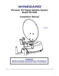
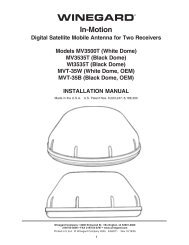
Introduction/How Does Digital Satellite TV Work?About this manual —We hope this manual will provide clear instructions to install andoperate MV-4005. Two symbols have been used —Indicates caution should be taken!Indicates suggestions to makeprocesses easier for you.!IntroductionCongratulations! You have purchased one of<strong>Winegard</strong>’s latest developments in the mobile satellitereception product line —the Movin’ View TM . Thissystem, used with your digital satellite receiver, willdeliver the best reception possible using GPS (GlobalPositioning System) and precision gyroscopes.How Does Digital SatelliteTV Work?Satellite programming originates from an “uplink”facility on Earth — the facility receives many signalsfrom different sources, combines the signals digitallyand transmits to the satellites. The satellites (22,300miles above Earth) receive the uplink signal, amplifyit and then transmit it back to earth inthe Ku frequency band. This signalis concentrated and reflected tothe LNBF* located at the “focalpoint” of the dish. The LNBF amplifiesand converts the signal to the 950to 1450 MHz range. The signal is thenpassed through a coaxial cable to the receiverwhere individual channel selectionand processing take place.* Low Noise Block Converter FeedFor Programming information call:DISH NETWORK ® - 1-800-333-DISH (1-800-333-3474)DIRECTV ® - 1-800-DIRECTV (1-800-347-3288)EXPRESSVU ® - 1-888-SKYDISH (1-888-759-3474)Your new <strong>Winegard</strong> RV Digital Satellite System is aneasy-to-use satellite TV reception system. Because itmounts on the top of your recreational vehicle, it goeswhere you go and provides quality reception of digitalsatellite signals. Check with your program provider forexact coverage area.MV-4005 features:• GPS technology• Easy “one-button” operation• Compatible with most digital satellite receivers• Ability to toggle between satellites using remotecontrol, if subscribing to multisatellite programming• <strong>Winegard</strong> warrantyDIGITAL BROADCAST SYSTEMSATELLITE(S)HIGH POWER KU-BANDDOWNLINK SIGNALWINEGARD DIGITAL SATELLITESYSTEM ANTENNAPROGRAMMING UPLINKCONTROL CENTERSUPLINK SIGNALRECEIVERTELEVISIONSETDIRECTV ® is an official trademark of DIRECTV, a unit of GM Hughes Electronics Corporation.DISH Network TM is an official trademark of EchoStar Communications Corporaton.2
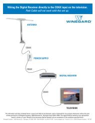
To toggle between satellites when subscribing to multi-satellite programming—While in Sleep Mode, the MV-4005 will toggle betweenthe primary and seconday satellites for eitherDISH Network or DIRECTV. Both have programmingon more than one satelite.When a channel isselected on the remote control and is not on thesatellite currently selected, the unit will automaticallymove to the correct satellite.DIRECTV programming1. DIRECTV receivers must be set for oval dish 2sat selection to enable toggling between primary101°W satellite and alternate 119°W satelliteonly. (Consult receiver manual for procedure.)After receiver is set for the correct dish selection,when you request a channel located on a differentsatellite, the unit will automatically move tothat satellite.DISH Network programming (DISH 500)DISH Network receivers must have the “SW42”switch installed in order to toggle between the primary119 satellite and the alternate 110 satellite.(Consult your receiver manual for the procedure toreach the “check switch” menu.)If a switch other than SW42 appears, or youhave an X in one of the boxes below the satellites,repeat Check Switch Steps.5. Your system is now set up to toggle between satellites.It will automatically move to the correctsatellite when a channel is selected with your remotecontrol.NOTE: Once these steps are completed, youwon’t have to perform this test again, unlessCheck Switch was performed on another satellitedish, such as a home dish.!Toggle: Your <strong>Winegard</strong> Automaticsatellite dish will move from theprimary to the alternate satellite inorder to receive multi-satelliteprogramming.To install the “SW42” switch:1. Before turning on your MV-4005 system, makesure that your satellite receiver and television areturned on and your receiver is on the “point dish”menu. (Consult your owner’s manual to reach thismenu.)2. While the vehicle is stationary, turn on the MV-4005 system and wait for signal acquisition onsatellite 119.3. After signal is acquired, the system will continuouslytrack the signal for approximately 6minutes. At the end of 6 minutes, the unit will entersleep mode. You now have 6 minutes tocomplete Check Switch test. Consult your receivermanual for instructions on running this test. Be surethat Superdish and Alternate are unchecked if applicable.Onscreen options may vary by receiver.4. During the Check Switch Test, the receiver willbegin checking the switch by toggling betweensatellites. When this is completed, SW42 will appearon the screen. It will be at the top of thescreen, satellite designations will be below, showingodd and even transponders. See illustration.Input: 1 1 1 1Satellite: 119 119 110 110Polarity: Odd Even Odd EvenStatus:Install SummarySatellite reception verifiedSuperdishSW42AlternateCancel Test HelpCheck Switch screen displayNOTE: Be sure the “Superdish” and “Alternate”boxes ARE NOT checked.5
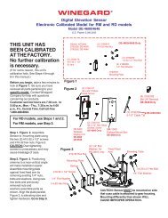
Parts Included • Tools Needed • How to UnpackPARTS INCLUDED:1 Radome1 Power switch2 Wall plates (white & brown)1 Surface mount box1 Cable entry plate2 Cable ties3 Base feet1 Coax connector1 Barrel connector1 large yellow spade connector2 small red spade connectorsAll required screws, washers, bolts, and nylocks1 base with electronics, dish, single LNBFSilicone sealantSurface WipesTOOLS NEEDED FOR UNPACKING & INSTALLATION:LevelDrill w/3/4” bit1-1/4” hole saw (if mounting switch in wall)Phillips screw driver #23/8” Open end wrench7/16” Open end wrenchSealant (consult RV manufacturer for proper typefor your roof material)UNPACKING THE UNIT1. Open box and remove packing material.!If using knife to opencarton, BE CAREFUL.Do not cut the dome onthe unit.LIFT UNIT STRAIGHT UPOUT OF CARTON!!BE CAREFUL whenremoving unit. Dome isattached to base byonly 3 pieces of tape,NOT BY SCREWS.2. Lift dome out of box vertically. Then lift unit out ofbox vertically. Do not turn box and “roll” out, or turnupside down to remove.USE 2 PEOPLEwhen removing the unitfrom the carton.!DO NOT PAINT DOME!Painting dome willcause signaldegradation.6
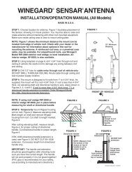
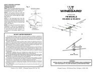
Base DiagramFIGURE 2SWITCH LOCATION(SIDE OF BOX, SEE PAGE 3)COAX CABLE ATCONTROL BOXCONTROLBOX TO LNBFEL MOTORGPS ANTENNACABLE+12VDCPOWER CABLEGPSANTENNA CENTERLINE OF THEVEHICLECONTROLBOX(DETAILBELOW)AZ MOTORFOOTMUST BEPARALLELTO THECENTER LINEOF THEVEHICLELNBFVOLTAGEREFLECTORCONTROL BOX DETAILELECTRONICS INTERIOR VIEWVehicleFrontAMountOption AVehicleFrontB(#1 represents Switch DOWN; #0 represents Switch up)Sat. Rcvr. Mt. Option Switch Set Position........................... 1 2 3 4 5 6 7 8DIRECTV ...................... A ....... 0 .. 0 .. 0 .. 0 .. 0 .. 0 .. 0 .. 1(FACTORY PRESET)DIRECTV ...................... B ....... 1 .. 0 .. 0 .. 0 .. 0 .. 0 .. 0 .. 1DISH NETWORK .................. A ....... 0 .. 0 .. 0 .. 1 .. 0 .. 0 .. 1 .. 1DISH NETWORK .................. B ......... 1 .. 0 .. 0 .. 1 .. 0 .. 0 .. 1 .. 1ExpressVu ..................... A ....... 0 .. 1 .. 0 .. 1 .. 1 .. 0 .. 1 .. 1ExpressVu ..................... B ....... 1 .. 1 .. 0 .. 1 .. 1 .. 0 .. 1 .. 1RECEIVERMountOption BP4ELEVATIONP3AZIMUTHLNBF7
<strong>Installation</strong>Installing unit on roof of vehicle —Install in DRY conditions only!IMPORTANT! Do not install this systemin the rain, or under any wet conditions. Moisturemay affect electronics and void yourwarranty!1. For best performance and to reduce signal acquisitiontime, park vehicle on a level surface;level the RV.2. Select a level spot on your roof for installation.!6. Place the unit on the roof in its permanent locationand mark around the base bracket, Figure 4. (Makesure the rear adjustable base foot is parallel withthe center line of the vehicle. Refer to page 3, Figure1A ).7. Clean roof area where the base feet will be attachedto the roof. Do not erase your marks!FIGURE 4Using the chart,determine theminimum distancesto other equipment.Obstruction Ht. Unit Clearance8” .......................................... 4”10” ................................... 11.5”12” ...................................... 19”15” ...................................... 32”FIGURE 3UNIT BASEOBSTRUCTIONWARNING: Level the base front to back and sideto side. If base is not level the MV-4005 may requiremore time to locate the correct satelliteor may not locate the correct satellite.• Be sure no roof-mounted equipment isblocking the satellite “line of sight”, Fig. 3• You will need to decide where the wires will enterthe vehicle. A coax and a power wire (minimum 16gauge) will need to be run into the vehicle.WARNING: Many +12VDC sources can cause theunit to fail. Select a filtered source, preferably a dedicatedline to the battery.8. Put approved sealant in the areas markedfor the base feet. Place base feet on top of thesealant and screw down with the (4) #10screws (provided) for each foot.9. After all base feet are secured to roof, putsealant around edge of feet and over screws.Replace base on screws and reinstall nut.FIGURE 5BASE EXTERIOR3. Remove dome. Place dome in safe spot to avoiddamage. Place base on vehicle roof in the locationselected.4. Attach each mounting foot to base by securingwith two 7/16” nylocks. See page 7 for foot locations.5. After selecting location for unit (see number 2),put the unit on the centerline of the vehicle.REAR MOUNTING FOOT MUST BE PARALLELWITH THE CENTER LINE OF VEHICLE. See pg. 7.8
<strong>Installation</strong>GPS installation —10. The GPS antenna is pre-wired and has a 1 metercable running through one of the connectors.Determine location for GPS antenna. It is recommendedyou place the GPS antenna 3 feet fromdome.The recommended location for the GPS antenna isbased on having a level location and a clear view ofthe sky for the best satellite signal acquisition. Do notsecure GPS antenna to roof at this time.IMPORTANT! The GPS must be located minimum of3 feet away from obstructions on roof of vehicle. Antennamust have a clear view of the sky for properoperation.Cable entry installation —1. Decide the best location for the cables to enterthe vehicle, and the location of the switch and receiver(see “Installing the switch and receiver”onpage 10). Drill a 1/2” hole in the roof, push wires inside.Make proper connections.You must have filtered +12 VDC power source.2. Place cable-entry plate over hole and cables.Screw in place. Seal plate and screw holes with approvedsealant (not included).3. Depending on the length of the cable on the roof,you may need to use cable clamps or wire ties (notprovided) between the unit and your cable-entry plate.Clamping the cable every 12”-16” should eliminateany unnecessary cable movement, Figure 6.INSTALLING THE POWER SWITCH1. Choose a location to install the MV-4005 powerON/OFF switch. Remember when selecting a locationthat you will need to run the +12VDC power cablefrom the MV-4005 to the switch. Be sure theswitch is in the OFF position before continuing.See Figure 9 page 10.Wall or panel mount: Drill 1-1/4” hole, pull wiresthrough wall or panel.Surface mount: Determine location and direction ofbox. Mount box and feed wire into one of the box openings. Select plate cover (brown or white provided) andsnap the rocker switch into the switch plate. Be sureswitch is off!2. Connect the ground wire from the vehicle and theBLACK ground wire from the MV-4005 together,using large yellow spade connector.3. Connect the YELLOW spade connector tothe silver spade on the switch.4. Connect the RED wire from the MV unit to thesmall RED spade connector.5. Connect small RED spade connector to centerspade on switch.6. Connect the +12 V power wire from the vehicle toa small RED spade connector.7. Connect small RED spade connect to isolatedspade on switch.INSTALLING THE POWER SWITCH DIAGRAMFIGURE 5ON/OFF ROCKER SWITCHWITH LIGHT(Shown in OFF position.)FIGURE 4CABLE-ENTRYCABLECLAMPSINSTALLING THE DOMEInsert screw in holes on domerim. Be sure bolt is vertical;not tilted to side. Tighten to20 in.-lb., or approximatelyuntil washer is visiblearound screw head.CAUTION:DO NOTOVERTIGHTEN!!QUADREXSCREW WITHRUBBERWASHER(USE #2PHILLIPS)STEPS 2 & 3TWO GROUND WIRES1 FROM VEHICLE1 BLACK WIRE FROMSATELLITE DISHSTEPS 4 & 5RED POWERWIRE FROMDISHSTEPS 6 &7+12 V FROM VEHICLETerminals on switch have to be bent to fit in surfacemount box.9
<strong>Installation</strong> • WiringCONNECTING THE RECEIVER —Connect the coax cable from the roof to the“Satellite In” connection on the receiver.(A dual receiver upgrade kit is available. Contact<strong>Winegard</strong> Company for more information.)INITIALIZING ---1. Be sure vehicle is in a location free of all obstructionsand with a clear view of the southern sky.2. DO NOT MOVE VEHICLE during the firstinitialization. Power up unit, turn on receiver. FORTHE FIRST TIME ONLY, the unit may take up to10 minutes to initially find the satellite signal. TheGPS is also initializing at this time. After the GPSinitializes, the unit will begin searching for thecorrect satellite. See page 4 for detail of operation.3. If the GPS does not initialize at this time, turnoff the unit. You may need to move the GPSantenna to a different location on your roof. Afteryou move the GPS, DO NOT SECURE TO ROOF.4. TEST YOUR SYSTEM BEFORE SECURINGTHE GPS ANTENNA. Verify that the dish hasfound the correct satellite by checking thereceiver’s signal meter screen.5. After the correct satellite has been found, secureGPS antenna by removing adhesive backingand securing to roof.10
PROBLEMSOLUTIONTroubleshootingThe MV-4005 does not attempt to find a satellite orit never moves.1. Check your Power switch to verify that it is in the ON position.2. Check +12 V wires at unit to verify power. Check fuse on electronics.3. Verify that the MV-4005 has had it’s shipping straps removed.These straps are located inside the dome and keep the dish frommoving until it is installed.The MV-4005 turns on and moves for a few secondsthen stops and never moves again.The dish never stops on any of the signals thatit sees.With DIRECTV, the dish will find the alternateSatellite but it never finds the primary satellite.The dish stopped searching and is making littlecircles in the same area but I don’t have a signal.1. Wait 10 minutes. The unit can take up to 10 minutes to acquireGPS. If it normally takes 10 minutes to acquire GPS, contact<strong>Winegard</strong>.2. If you feel comfortable doing so, look on the roof of the vehicle toverify that the GPS antenna is at least 3 feet from the dome andother objects on roof. Failure to have the GPS antenna at least 3feet away can cause the dome to interfere with GPS aquisition. Ifantenna is too close, move it.3. Check the GPS antenna cable for damage. If there is apinched or damaged section, contact <strong>Winegard</strong>.1. Make sure that your receiver is set up correctly.For DISH Network, the check switch should read either “Unknown”or “SW42”.For DirecTV the receiver should be set for a Two Satellite OvalDish.2. Make sure the receiver has power and the satellite dish is connectedto the “Sat In”.Make sure that the Switches on the Electronics Control Box areset for DirecTV. See page 3. These switches are found underthe dome, inside the Electronics Control Box.1. Most likely the dish has locked on the satellite. Sometimes thereceiver refuses to show it until its ready. To help it get ready,turn the receiver, not the dish, OFF. Wait a few minutes andturn it back on.2. For Dish Network users, the Dish might be set to find DirecTV.See page 3 for instructions on setting it for Dish Network.I am not getting all the DISH Network channelsI subscribed to.The MV-4005 never sees any signals, it just keepssearching.The MV-4005 works when it is stationary but failswhen the vehicle is in motion.1. Go to the check switch menu in receiver. Make sure that it’sset for SW42 and lists both even and odd transponders on satellites110 and 119.1. Rain, Snow or excessive Dew on the dome can interrupt thesignal. Snow and Dew can be brushed off the dome. If Heavy rainor Snow fall is blocking the signal, it may be necessary to wait untilthe weather clears.2. Check to see if the Southern sky is clear. Trees, Buildings, Largesigns or an Overpass can block the signal. Find an area where youcan be sure that this is not the problem and try again.3. Make sure the receiver has power and the satellite dish is connectedto the “Sat In”.4. Verify electronics board inside dome is installed in proper location.Board should be placed so that magnets on unit’s gears passthrough electronics board slot without hitting interior boards.Verify that the switches are set for the install option used for yourvehicle. Option A has the rear mounting foot facing off the backof the vehicle. Option B has the rear mounting foot facing off thefront of vehicle. See page 3 for switch settings.11
Specifications & WarrantyFeatures and specifications• One button operation.• GPS satellite signal acquisition.• Depending on receiver type, you can accesssatellites 119°, 110°, 101° or 92°.• No user input required.• No data port required for DISH Network ® ,DIRECTV ® or ExpressVu.• Tracking greater than 30°/sec.• Elevation range 18° to 74.5°;azimuth unlimited.• 35’ power cable and 35’ coaxial cable included.• Dome UV protected.• Black color compatible with all vehicles.• Compact size —32” diameter, 15-3/4” heightWeight of unit - 32 lbs.Shipping weight - 44 lbs.• Operating temperature-13°F to +140°FTWO YEAR LIMITED WARRANTY<strong>Winegard</strong> Company warrants this <strong>Winegard</strong> product (excluding receiver) against any defects in materials orworkmanship within two (2) years from date of purchase. No warranty claim will be honored unless at the time the claimis made, you present proof of purchase to an authorized <strong>Winegard</strong> dealer (if unknown, please contact <strong>Winegard</strong>Company, 3000 Kirkwood Street, Burlington, Iowa 52601-2000, telephone 319-754-0600).<strong>Winegard</strong> Company (at its option) will either repair or replace the defective product at no charge to you. This warrantycovers parts, but does not cover any costs incurred in removal, shipping or reinstallation of the product. This limitedwarranty does not apply if the product is damaged, deteriorates, malfunctions or fails from: misuse, improperinstallation, abuse, neglect, accident, tampering, modification of the product as originally manufactured by <strong>Winegard</strong>,usage not in accordance with product instructions or acts of nature such as damage caused by wind, lightning, ice orcorrosive environments such as salt spray and acid rain.The Two Year Warranty is provided on the condition that the equipment is properly delivered with all handling andfreight charges prepaid to your <strong>Winegard</strong> dealer for repair or return to our factory at the above address. <strong>Winegard</strong>dealers will arrange for the replacement or repair and return to you, without charge, the product which failed due todefective material or workmanship.WINEGARD COMPANY WILL NOT ASSUME ANY LIABILITIES FOR ANY OTHER WARRANTIES, EXPRESS ORIMPLIED, MADE BY ANY OTHER PERSON.ALL OTHER WARRANTIES WHETHER EXPRESS, IMPLIED OR STATUTORY INCLUDING WARRANTIES OFFITNESS FOR A PARTICULAR PURPOSE AND MERCHANTABILITY ARE LIMITED TO THE TWO YEAR PERIODOF THIS WRITTEN WARRANTY.The foregoing shall be the sole and exclusive remedy of any person whether in contract, tort or otherwise, and<strong>Winegard</strong> shall not be liable for incidental or consequential damage or commercial loss, or from any other loss ordamage except as set forth above.Some states do not allow limitations on how long an implied warranty lasts, or the exclusion of limitation of incidentalor consequential damages, so the above limitations or exclusions may not apply to you.This warranty gives you specific legal rights and you may also have other rights which vary from state to state.<strong>Winegard</strong> Company • 3000 Kirkwood Street • Burlington, IA 52601 • 319/754-0600 Fax 319/754-0787 • www.winegard.comPrinted in U.S.A. © 2005 <strong>Winegard</strong> Company 2451010 5/0512