Download the Catalog Data-Sheet PDF - LiveWire Electrical Supply
Download the Catalog Data-Sheet PDF - LiveWire Electrical Supply
Download the Catalog Data-Sheet PDF - LiveWire Electrical Supply

Create successful ePaper yourself
Turn your PDF publications into a flip-book with our unique Google optimized e-Paper software.
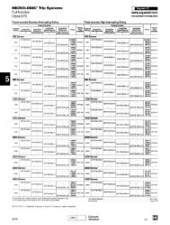
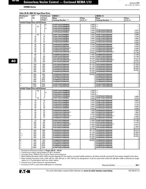
January 2001 Sensorless Vector Control — Enclosed NEMA 1/12Vol. 2, Ref. No. [0453]SV9000 Series40-Technical <strong>Data</strong>Table 40-69. SpecificationsFeature Description SV9000 Enclosed Products —NEMA 1 or NEMA 12Primary Design Features45 – 66 Hz Input Frequency StandardOutput: AC Volts Maximum Input Voltage BaseOutput Frequency Range: Hz .0 – 500Initial Output Current (CT)250% for 2 secondsOverload: 1 Minute (CT/VT) 150%/110%Enclosure Space HeaterOptionalOversize EnclosureStandardOutput ContactorOptionalBypass Motor StarterOptionalListingsULProtection FeaturesIncoming Line FusesOptionalAC Input Circuit Disconnect OptionalLine ReactorsStandardPhase Rotation InsensitiveStandardInput Phase Loss Protection StandardInput Overvoltage Protection StandardLine Surge ProtectionStandardOutput Short Circuit Protection StandardOutput Ground Fault Protection StandardOutput Phase ProtectionStandardOvertemperature Protection StandardDC Overvoltage ProtectionStandardDrive Overload ProtectionStandardMotor Overload Protection StandardProgrammer SoftwareOptionalKeypad LockoutStandardFault Alarm OutputStandardBuilt-In DiagnosticsStandardInput/Output Interface FeaturesSetup Adjustment Provisions:Remote Keypad/DisplayPersonal ComputerOperator Control Provisions:Drive Mounted Keypad/DisplayRemote Keypad/DisplayConventional Control ElementsSerial Communications115V AC Control CircuitSpeed Setting Inputs:KeypadPotentiometer/Voltage Signal4 – 20 mA Isolated4 – 20 mA Differential3 – 15 psigAnalog Outputs:Speed/FrequencyTorque/Load/CurrentMotor VoltageKilowatts0 – 10V DC Signals4 – 20 mA DC SignalsIsolated SignalsStandardStandardStandardStandardStandardStandardOptionalStandardStandardOptionalStandardOptionalStandardProgrammableProgrammableProgrammableOptionalStandardOptionalFeature Description SV9000 Enclosed Products —NEMA 1 or NEMA 12Input/Output Interface Features (Continued)Discrete Outputs:Fault AlarmDrive RunningDrive at Set SpeedOptional ParametersDry ContactsOpen Collector OutputsAdditional Discrete OutputsCommunications:RS-232RS-422/485DeviceNetModbus RTUInterbus-SProfibus-DPLonworks ®Performance FeaturesSensorless Vector ControlClosed Loop Vector ControlVolts/Hertz ControlIR and Slip CompensationElectronic ReversingDynamic BrakingDC BrakingPI Setpoint ControllerCritical Speed LockoutCurrent (Torque) LimitAdjustable Acceleration/DecelerationLinear or S Curve Accel/DecelJog at Preset SpeedStandardStandardProgrammable1411OptionalStandardOptionalOptionalOptionalOptionalOptionalOptionalStandardOptionalStandardStandardStandardOptional StandardProgrammableStandardStandardStandardStandardStandardThread/Preset Speeds 7Automatic RestartSelectableCoasting Motor StartStandardCoast or Ramp Stop Selection StandardElapsed Time MeterStandardCarrier Frequency Adjustment 1 – 16 kHzStandard Conditions for Application and ServiceOperating Ambient Temperature 0 – 40°CStorage Temperature -40 – 60°CHumidity (Maximum),95%Non-condensingAltitude (Maximum without Derate) 3300 ft. (1000m)Line Voltage Variation +10/-15%Line Frequency Variation45 – 66 HzEfficiency >96%Power Factor (Displacement) .96 Some horsepowers include dynamic braking chopper circuit asstandard — refer to individual drive sections.Table 40-70. Standard I/O Specifications6 – Digital Input Programmable 24V: “0” ≤ 10V, “1” ≥ 18V,R i > 5 k1 – Analog Input Voltage: 0 – ±10V, R i > 200 kCurrent: 0 (4) – 20 mA, R i = 250 k2 – Digital Output Programmable Form C Relays250V AC 2 Amp or30V DC2 Amp resistive1 – Digital Output Programmable Open collector 48V DC 50 mA1 – Analog Output Programmable 0 – 20 mA, impedance 500 ohms,resolution 106 ±3%CAT.201.01.T.EFor more information contact Cutler-Hammer at: www.ch.cutler-hammer.com/catalog
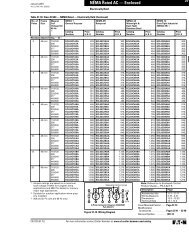
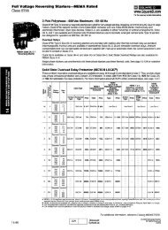
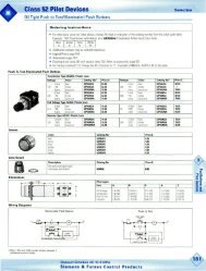
40-48Sensorless Vector Control — Enclosed NEMA 1/12SV9000 SeriesJanuary 2001Vol. 2, Ref. No. [0456]Control/Communications Options — SV9000 EnclosedTable 40-75. Available Control/Communications OptionsOption Description OptionType40CC1DI3I4LL7L8L9L10MM5M6M8M9Input Disconnect 65 kAIC — High Interrupting Motor Circuit Protector (HMCP) that provides a means of short circuit protection for <strong>the</strong>power cables between it and <strong>the</strong> SV9000, and protection from high-level ground faults on <strong>the</strong> power cable. Allows a convenient means ofdisconnecting <strong>the</strong> SV9000 from <strong>the</strong> line and <strong>the</strong> operating mechanism can be padlocked in <strong>the</strong> OFF position. This is factory mounted in <strong>the</strong>enclosure.Input Line Fuses (200 kAIC) — Provides high-level fault protection of <strong>the</strong> SV9000 input power circuit from <strong>the</strong> load side of <strong>the</strong> fuses to <strong>the</strong>input side of <strong>the</strong> power transistors. This option consists of three 200 kA fuses, which are factory mounted in <strong>the</strong> enclosure.Output Contactor — Provides a means for positive disconnection of <strong>the</strong> drive output from <strong>the</strong> motor terminals. The contactor coil iscontrolled by <strong>the</strong> drive’s run or permissive logic. NC and NO auxiliary contacts rated at 10A, 600V AC are provided for customer use.Bypass Options I3, I4, X3 and X4 include an Output Contactor as standard. This option includes a low VA 115V AC fused Control PowerTransformer and is factory mounted in <strong>the</strong> enclosure.Manual IOB Bypass Controller — The Manual INVERTER/OFF/BYPASS (IOB) — 3-contactor — bypass option provides a means ofbypassing <strong>the</strong> SV9000, allowing <strong>the</strong> AC motor to be operated at full speed directly from <strong>the</strong> AC supply line. This option consists of aninput disconnect, a fused control power transformer, and a full voltage bypass starter with a door mounted IOB selector switch. Forapplications up to 100 hp, a Freedom Series IEC input contactor, a Freedom Series IEC output contactor, and a Freedom Series IEC starterwith a bimetallic overload relay is included. For applications above 100 hp, an Advantage input contactor, an Advantage output contactorand an Advantage starter with electronic overload protection is included. The contactors are mechanically and electrically interlocked (seepower diagram on Page 40-44).Manual HOA Bypass Controller — The Manual HAND/OFF/AUTO (HOA) — 3-contactor — bypass option provides a means of bypassing<strong>the</strong> SV9000, allowing <strong>the</strong> AC motor to be operated at full speed directly from <strong>the</strong> AC supply line. This option consists of an inputdisconnect, a fused control power transformer, and a full voltage bypass starter with a door mounted HOA selector switch and anINVERTER/BYPASS switch. The HOA switch provides <strong>the</strong> ability to start and stop <strong>the</strong> drive in <strong>the</strong> inverter mode. For applications up to 100hp, a Freedom Series IEC input contactor, a Freedom Series IEC output contactor, and a Freedom Series IEC starter with a bimetallicoverload relay is included. For applications above 100 hp, an Advantage input contactor, an Advantage output contactor and anAdvantage starter with electronic overload protection is included. The contactors are mechanically and electrically interlocked (see powerdiagram on Page 40-44).3% Input Line Reactor — Minimizes <strong>the</strong> risk of damage to <strong>the</strong> SV9000 as a result of line transients and excessive loading on <strong>the</strong> input filtercapacitors arising from connecting <strong>the</strong> SV9000 to a power distribution system with low impedance. The reactor adds impedance to <strong>the</strong>line, which reduces <strong>the</strong> internal power capacitor’s voltage peaks (ripple). The Line Reactor is also an effective way to attenuate harmonicsgenerated by <strong>the</strong> drive. All enclosed drives include this option, base catalog numbers with L suffix include separate 3% line reactormounted inside enclosure, all o<strong>the</strong>rs include nominal 3% line reactor integral to <strong>the</strong> drive.MotoRx (300 – 600 Ft.) 1000 V/us DV/DT Filter — Used to reduce transient voltage (DV/DT) and peak voltages at <strong>the</strong> motor terminals. Thisoption is comprised of a .5% line reactor, followed by capacitive filtering and an energy recovery/clamping circuit. Unlike <strong>the</strong> Output Filter(See option L10), <strong>the</strong> MotoRx recovers most of <strong>the</strong> energy from <strong>the</strong> voltage peaks, resulting in a lower voltage drop to <strong>the</strong> motor, and<strong>the</strong>refore conserving power. This option is used when <strong>the</strong> distance between a single motor and <strong>the</strong> drive is 300 – 600 feet (91 – 183m).This option can not be used with <strong>the</strong> Brake Chopper Circuit. The Output Filter (option L10) should be investigated as an alternative.MotoRx (100 – 300 Ft.) 1500 V/us DV/DT Filter — Used to reduce transient voltage (DV/DT) and peak voltages at <strong>the</strong> motor terminals.This option is comprised of a .5% line reactor, followed by capacitive filtering and an energy recovery/clamping circuit. Unlike <strong>the</strong> OutputFilter (See option L10), <strong>the</strong> MotoRx recovers most of <strong>the</strong> energy from <strong>the</strong> voltage peaks, resulting in a lower voltage drop to <strong>the</strong> motor,and <strong>the</strong>refore conserving power. This option can be used with up to 300 feet (91m) of cable between <strong>the</strong> drive and a single motor. TheMotoRx is recommended for cable lengths exceeding 100 ft. (30m) with a drive of 3 hp and above, and for cable lengths of 33 ft. (10m) with adrive of 2 hp and below. This option cannot be used with <strong>the</strong> Brake Chopper Circuit. The Output Filter (option L10) should be investigated asan alternative.EMI/RFI Filter — Intended for use as conducted noise filters when AF drives are used around or near sensitive equipment such as computers,medical instruments, or communication or navigation radios. Helps to comply with FCC requirements by filtering unwanted noise in<strong>the</strong> range of 10 kHz to 30 MHz. This option is factory mounted in <strong>the</strong> enclosure. This is not intended to meet <strong>the</strong> EMC requirements of CE.Output Filter — Used to reduce <strong>the</strong> transient voltage (DV/DT) at <strong>the</strong> motor terminals. The Output Filter is recommended for cable lengthsexceeding 100 ft. (30m) with a drive of 3 hp and above, for cable lengths of 33 ft. (10m) with a drive of 2 hp and below, or for a drive ratedat 525 – 690V. This option is mounted in <strong>the</strong> enclosure, and may be used in conjunction with a Brake Chopper Circuit.3 – 15 psig Follower — Provides a pneumatic transducer which converts a 3 – 15 psig pneumatic signal to ei<strong>the</strong>r 0 – 8V DC or a1 – 9V DC signal interface with <strong>the</strong> SV9000. The circuit board is mounted on <strong>the</strong> inside of <strong>the</strong> front enclosure panel and connects to <strong>the</strong>user’s pneumatic control system via 6 ft. (1.8m) of flexible tubing and a 1/4 inch (6.4 mm) brass tube union.4 Channel – 120V AC Control Interface — Allows <strong>the</strong> SV9000 to be interfaced with remote 120V AC controls. This option uses four interposingrelays to convert up to four 120V AC input signals into dry contact inputs. In addition, each relay coil has arc suppression circuitryto reduce <strong>the</strong> effects of EMI on o<strong>the</strong>r components. The interface is a printed circuit board that is mounted on <strong>the</strong> inside of <strong>the</strong> enclosuredoor.Isolated Process Follower — Provides signal isolation in order to avoid common mode currents (ground loops) between <strong>the</strong> AF drive andremote instrumentation and control equipment. This option provides one isolated analog (0 – 10V DC/4 – 20 mA) input, and two isolatedanalog (0 – 10V DC/4 – 20 mA) outputs. The follower is a printed circuit board that is mounted on <strong>the</strong> inside of <strong>the</strong> enclosure door.Door-Mounted Speed Potentiometer — Provides <strong>the</strong> SV9000 with <strong>the</strong> ability to adjust <strong>the</strong> frequency reference using a door-mountedpotentiometer. This option uses <strong>the</strong> 10 VDC reference to generate a 0 – 10V signal at <strong>the</strong> analog voltage input signal terminal. When <strong>the</strong>HOA bypass option is added, <strong>the</strong> speed is controlled when <strong>the</strong> HOA switch is in <strong>the</strong> hand position. Without <strong>the</strong> HOA bypass option, a 2-position switch (labeled local/remote) is provided to select speed reference from <strong>the</strong> Speed Potentiometer or a remote speed signal.Door-Mounted Speed Potentiometer with HOA Selector Switch — Provides <strong>the</strong> SV9000 with <strong>the</strong> ability to start/stop and adjust <strong>the</strong> speedreference from door-mounted control devices or remotely from customer supplied inputs. In HAND position, <strong>the</strong> drive will start and <strong>the</strong>speed is controlled by <strong>the</strong> door-mounted speed potentiometer. The drive will be disabled in <strong>the</strong> OFF position. When AUTO is selected, <strong>the</strong>run enable and speed reference are controlled from remote inputs. Speed reference can be ei<strong>the</strong>r 0 – 10V DC or 4 – 20 mA. The drive defaultis 4 – 20 mA, parameter is field programmable. Run enable is controlled by a dry contact closure. This option requires a customer supplied115V power source. If not available, add T1 option.InputInputOutputBypassBypassInputOutputOutputInputOutputControlControlControlControlControlFor more information contact Cutler-Hammer at: www.ch.cutler-hammer.com/catalogCAT.201.01.T.E
January 2001 Sensorless Vector Control — Enclosed NEMA 1/12Vol. 2, Ref. No. [0457]SV9000 Series40-Table 40-75. Available Control/Communications Options (Continued)Option Description Option TypeM158 Channel – 120V AC Control Interface — Allows <strong>the</strong> SV9000 to be interfaced with remote 115V AC controls. This option uses eightinterposing relays to convert up to eight 120V AC input signals into dry contact inputs. In addition, each relay coil has arc suppressioncircuitry to reduce <strong>the</strong> effects of EMI on o<strong>the</strong>r components. The interface is a printed circuit board that is mounted on <strong>the</strong> inside of <strong>the</strong>enclosure door.N1 Custom Plastic Nameplate — A 3 x 5 inch laminated plastic sheet, which can include up to two lines of 15 characters each. EnclosureN2 Custom Metal Nameplate — A 3 x 5 inch stainless steel sheet, which can include up to two lines of 15 characters each. EnclosureT1 115V Control Transformer – 105 VA — Provides a fused control power transformer with additional 105 VA at 115V for customer use. ControlT2 115V Control Transformer – 300 VA — Provides a fused control power transformer with additional 300 VA at 115V for customer use. ControlT3 115V Control Transformer – 550 VA — Provides a fused control power transformer with additional 550 VA at 115V for customer use. ControlV1 Floor Stand 22" — Converts a Size 1 or 2, normally wall mounted enclosure to a floor standing enclosure with a height of 22" Enclosure(558.8 mm).V2 Space Heater — Prevents condensation from forming in <strong>the</strong> enclosure when <strong>the</strong> drive is inactive or in storage. Includes a <strong>the</strong>rmostatfor variable temperature control. A 200W heater is installed in enclosures 0 and 1, and a 400W heater is installed in enclosures 2 – 6.Requires a customer supplied 115V remote supply source.EnclosureV4 Floor Stand 12" — Converts a Size 2, normally wall mounted enclosure to a floor standing enclosure with a height of 12" (304.8 mm). EnclosureV5 10" Expansion — In a Size 5 enclosure, <strong>the</strong> extension allows for bottom cable entry and additional space for customer mountedcomponents.NOTE: Enclosure expansion rated NEMA 1 only.EnclosureV6X3X4X5X6X7Y4Y520" Expansion — In a Size 5 enclosure, <strong>the</strong> extension allows for bottom cable entry and additional space for customer mountedcomponents. When <strong>the</strong> Output Filter (option L10) is selected for a drive using a Size 5 enclosure, this expansion box is required andincluded in <strong>the</strong> option pricing.NOTE: Enclosure expansion rated NEMA 1 only.Auto Transfer IOB Bypass Controller — The Auto INVERTER/OFF/BYPASS (IOB) — 3-contactor — bypass option provides a means ofbypassing <strong>the</strong> SV9000, allowing <strong>the</strong> AC motor to be operated at full speed directly from <strong>the</strong> AC supply line. The circuitry provides anautomatic transfer of <strong>the</strong> load to “across <strong>the</strong> line” operation after a drive trip. This option consists of an input disconnect, a fusedcontrol power transformer, and a full voltage bypass starter with a door mounted IOB selector switch. For applications up to 100 hp,a Freedom Series IEC input contactor, a Freedom Series IEC output contactor, and a Freedom Series IEC starter with a bimetallic overloadrelay is included. For applications above 100 hp, an Advantage input contactor, an Advantage output contactor and an Advantagestarter with electronic overload protection is included. The contactors are mechanically and electrically interlocked (see power diagramon Page 40-44). Door mounted pilot lights are provided which indicate bypass or inverter operation. A green light indicateswhen <strong>the</strong> motor is running in inverter mode and an amber light indicates when <strong>the</strong> motor is running in bypass mode.WARNING: The motor may restart when <strong>the</strong> overcurrent relay is reset when operating in bypass, unless <strong>the</strong> IOB selector switch isturned to <strong>the</strong> OFF position.Auto Transfer HOA Bypass Controller – The Manual HAND/OFF/AUTO (HOA) — 3-contactor — bypass option provides a means ofbypassing <strong>the</strong> SV9000, allowing <strong>the</strong> AC motor to be operated at full speed directly from <strong>the</strong> AC supply line. The circuitry provides anautomatic transfer of <strong>the</strong> load to “across <strong>the</strong> line” operation after a drive trip. This option consists of an input disconnect, a fusedcontrol power transformer, and a full voltage bypass starter with a door mounted HOA selector switch and an INVERTER/BYPASSswitch. The HOA switch provides <strong>the</strong> ability to start and stop <strong>the</strong> drive in ei<strong>the</strong>r mode. For applications up to 100 hp, a Freedom SeriesIEC input contactor, a Freedom Series IEC output contactor, and a Freedom Series IEC starter with a bimetallic overload relay is included.For applications above 100 hp, an Advantage input contactor, an Advantage output contactor and an Advantage starter with electronicoverload protection is included. The contactors are mechanically and electrically interlocked (see power diagram on Page 40-44). Doormounted pilot lights are provided which indicate bypass or inverter operation. A green light indicates when <strong>the</strong> motor is running ininverter mode and an amber light indicates when <strong>the</strong> motor is running in bypass mode.WARNING: The motor may restart when <strong>the</strong> overcurrent relay is reset when operating in bypass, unless <strong>the</strong> IOB selector switch isturned to <strong>the</strong> OFF position.Bypass Pilot Lights for I3, I4 Bypass Options — A green light indicates when <strong>the</strong> motor is running in inverter mode and an amber lightindicates when <strong>the</strong> motor is running in bypass mode. The lights are mounted on <strong>the</strong> enclosure door, above <strong>the</strong> switches.Dual Overloads for Bypass — This option is recommended when a single drive is operating 2 motors in <strong>the</strong> bypass mode and overloadcurrent protection is needed for each of <strong>the</strong> motors. The standard configuration includes two bimetallic overload relays, eachsized to protect a motor with 50% of <strong>the</strong> drive hp rating. For example, a 100 hp drive would include two overload relays sized to protecttwo 50 hp motors. The relays are mounted within <strong>the</strong> enclosure, and are manually resettable.Bypass Test Switch for I3, X3, I4 and X4 — Allows <strong>the</strong> user to energize <strong>the</strong> AF drive for testing while operating <strong>the</strong> motor on <strong>the</strong> bypasscontroller. The Test Switch is mounted on <strong>the</strong> inside of <strong>the</strong> enclosure door.Single Overload Relay — Uses a bimetallic overload relay to provide additional overload current protection to <strong>the</strong> motor on configurationswithout bypass options. It is included with <strong>the</strong> Bypass Configurations for overload current protection in <strong>the</strong> bypass mode. TheOverload Relay is mounted within <strong>the</strong> enclosure, and is manually resettable.Dual Overload Relays — This option is recommended when a single drive is operating 2 motors and overload current protection isneeded for each of <strong>the</strong> motors. The standard configuration includes two bimetallic overload relays, each sized to protect a motor with50% of <strong>the</strong> drive hp rating. For example, a 100 hp drive would include two overload relays sized to protect two 50 hp motors. Therelays are mounted within <strong>the</strong> enclosure, and are manually resettable.Note: For pricing and availability, see Product Selection for base drive voltage required, Pages 40-60 – 40-73.AccessoriesFor Base Drive Spare Parts Kits, see Page 40-32.ControlEnclosureBypassBypassAddl.BypassAddl.BypassAddl.BypassOutputOutputCAT.201.01.T.EFor more information contact Cutler-Hammer at: www.ch.cutler-hammer.com/catalog
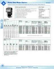
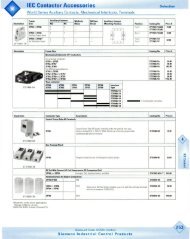
40-54Sensorless Vector Control — Enclosed NEMA 1/12SV9000 SeriesJanuary 2001Vol. 2, Ref. No. [0462]Table 40-80. Approximate Dimensions and Shipping Weight — Enclosed ProductsEnclosureSizeDimensions in Inches (mm)WideAHighBDeepCMounting H Min. Air SpaceD D1 E E1 F G G1 J K4 26.40(670.6)92.46(2348.5)19.39(492.5)19.50(495.3)3.25(82.6)23.00(584.2)1.50(38.1)11.74(298.2)5.51(140.0).93(23.6)89.35(2269.5)4.00(101.6)3.00(76.2)Table 40-80. Approximate Dimensions and Shipping Weight — Enclosed Products (Continued)EnclosureSizeDimensions in Inches (mm)Cable EntryL M N P RDoor ClearanceST U V W RR SS TT UU VVMax.Approx.Ship. Wt.Lbs. (kg)4 5.25(133.4)23.38(593.9)13.82(351.0)1.00(25.4)11.24(285.5)26.35(669.3)1.50(38.1)8.01(203.5)4.75(120.7)— 90.00(2286.0).75(19.1)1.26(32.0)— — 825 (375)40.50 (12.7)Lifting Eyes2 PlacesJKMPFor CableEntryVULRRHBSTTop View.44 (11.2)Mounting Holes6 PlacesRFor CableEntryFNCSSTTAG1GD1E1DENEMA 1, NEMA 12 , Size 4Bottom ViewFor Reference Only,Dimensions Subjectto Change.Figure 40-16. Approximate Dimensions NEMA 12 includes cover plates over louvers.For more information contact Cutler-Hammer at: www.ch.cutler-hammer.com/catalogCAT.201.01.T.E
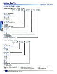
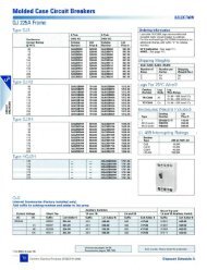
January 2001 Sensorless Vector Control — Enclosed NEMA 1/12Vol. 2, Ref. No. [0467]SV9000 Series40-<strong>Catalog</strong> Number SelectionTable 40-85. SV9000 Enclosed NEMA 1/12 Drive <strong>Catalog</strong> Numbering SystemBuild Alphabetically and Numerically.If 208V, "8" Must BeAdded as <strong>the</strong> First Suffix.Example:S V 9 0 1 5 A G V 5 M 0 A 0 0 C 1 X 3 X 7 8 C 1 X 3 X 7hphp Designations 3/4 to 7-1/2 10 to 400F07 -3/4 010 -10F10 -1 015 -15F15 - 1-1/2 020 -20F20 -2 025 -25F30 -3 030 -30F40 -4 040 -40F50 -5 04X - 40F75 - 7-1/2 050 -5005X - 50060 -60075 -75100 - 10010X - 100125 - 125150 - 150200 - 200250 - 250300 - 300400 - 400500 - 500600 - 600700 - 700800 - 800900 - 900H10 - 1000H11 - 1100Model SV9000Enclosed Options C - Input Disconnect (HMCP) 65 kAICC1 - Input Line Fuses 200 kAICD - Output ContactorDB2 - Dynamic Braking Resistors 2%SeriesDB5 - Dynamic Braking Resistors 5%(Only A at this time)I3 - Manual IOB Bypass ControllerI4 - Manual HOA Bypass ControllerL - 3% Input Line ReactorEnclosure RatingL7 - MotoRx — 300 – 600 Ft. (91 – 183m)1000 V/us DV/DT FilterG - NEMA 1L8 - MotoRx — 100 – 300 Ft. (30 – 91m)D - NEMA 121500 V/us DV/DT FilterL9 - EMI/RFI FilterL10 - Output FilterTorqueMM5- 3 – 15 psig Follower- 4 Channel — 120V AC Control InterfaceC - ConstantM6 - Isolated Process FollowerV - VariableM8 - Speed Potentiometer M9 - Speed Potentiometer with HOAM15 - 8 Channel — 120V AC Control InterfaceVoltageN1N2- Custom Plastic Nameplate- Custom Metal Nameplate2 - 208V , 230VT1 - 115 Volt Control Transformer — 105 VA5 - 480VT2 - 115 Volt Control Transformer — 300 VA6 - 575VT3 - 115 Volt Control Transformer — 550 VAV1 - Floor Stand 22 inch (558.8 mm)V2 - Space HeaterControl Panel V4V5- Floor Stand 12 inch (304.8 mm)- 10 inch (254 mm) ExpansionM - SVMulti-line AlphanumericV6 - 20 inch (508 mm) ExpansionG - SVGraphicX3 - Auto Transfer IOB Bypass ControllerX4 - Auto Transfer HOA Bypass ControllerX5 - Bypass Pilot Lights for I3, I4 OptionsSoftware (O<strong>the</strong>r than 0 denotes Special)X6X7- Dual Overloads for Bypass- Bypass Test Switch for I3, X3, I4, X4Y4 - Single Overload RelayY5 - Dual Overload RelaysDynamic Braking Chopper Circuit A - No Chopper CircuitTypeInputInputOutputOutputOutputBypassBypassInputOutputOutputInputOutputControlControlControlControlControlControlEnclosureEnclosureControlControlControlEnclosureEnclosureEnclosureEnclosureEnclosureBypassBypassAddl. BypassAddl. BypassAddl. BypassOutputOutputControl/Communication Options 00 - No Modifications01 - 5 Digital Inputs, 2 Analog Inputs (1 Voltage,1 Current), 3 Relay Outputs, Analog (Current)Output, Thermistor Input, Encoder Input02 - 5 Digital Inputs, Relay Output, Thermistor Input03 - 5 Digital Inputs, 2 Analog (Voltage) Inputs,3 Relay Outputs, Analog (Voltage) Output,Thermistor Input, Encoder Input04 - 5 Digital Inputs, 3 Relay Outputs, Analog Output,Thermistor Input05 - Encoder Board30 - DeviceNet Network Communications31 - Profibus Network Communications32 - ModBus RTU Network Communications33 - InterBus S Network Communications34 - LonWorks Network Communications 208V requires 8 as first character in suffix. SVMulti-line is included as <strong>the</strong> standard Control Panel. Brake Chopper is a factory installed option only, see Adder tables on Pages 40-60 – 40-73. Note: External dynamic braking resistors not included. Referto Dynamic Braking Resistors section on Pages 40-80 – 40-93. Included as standard on some sizes, see individual voltage sections for base catalog numbers containing “B”. Base <strong>Catalog</strong> Numbers with L suffix include separate 3% line reactor mounted inside enclosure, all o<strong>the</strong>rs include nominal 3% line reactor integral to <strong>the</strong> drive. 04X (40 hp), 05X (50 hp) or 10X (100 hp) designations used when ei<strong>the</strong>r L7, L8, L9 or L10 is selected as single option or in combination with any o<strong>the</strong>r option. Includes local/remote speed reference switch. Some options are voltage and/or horsepower specific. Consult your Cutler-Hammer representative for details. See Pages 40-48 – 40-49 for descriptions. See Pages 40-46 – 40-47 for complete descriptions and prices. See Dynamic Braking Resistors section on Pages 40-80 – 40-93 for pricing and selection information.CAT.201.01.T.EFor more information contact Cutler-Hammer at: www.ch.cutler-hammer.com/catalog