REF. - ROMDIDAC
REF. - ROMDIDAC
REF. - ROMDIDAC

Create successful ePaper yourself
Turn your PDF publications into a flip-book with our unique Google optimized e-Paper software.
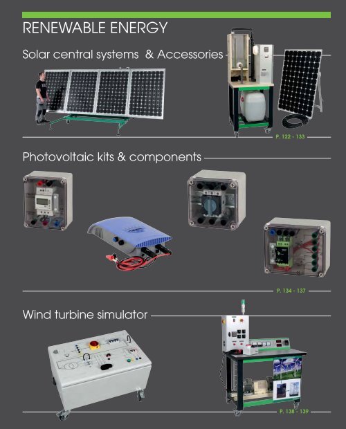
RENEWABLE ENERGYSolar central systems & AccessoriesP. 122 - 133Photovoltaic kits & componentsP. 134 - 137Wind turbine simulatorP. 138 - 139
SolarChoose your solution for studying photovoltaic energySOLAR CENTRAL UNIT WITH NETWORKINJECTION AND ISOLATED SITESOLAR CENTRAL UNITWITH NETWORK INJECTIONSOLAR CENTRAL UNITWITH ISOLATED SITEABx 2 x 2 x 2Complete solution comprising an electrical cabinet, 2portable photovoltaic panels (on frames), and all theaccessories required for studying solar energy on thenetwork and an isolated site.<strong>REF</strong>. SOL-1 SEE PAGE 124LOADING ZONE FOR USE ON SITE WITHELECTRICITY NETWORK OR ISOLATED SITEIn this version, zone A of the cabinet remains blank.Supplied with 2 portable photovoltaic panels (onframes), and all the accessories required for studyingsolar energy on the network.<strong>REF</strong>. SOL-2 SEE PAGE 125LOADING ZONE FOR USE ON SITE WITHELECTRICITY NETWORKIn this version, zone B of the cabinet remains blank.Supplied with 2 portable photovoltaic panels (onframes), and all the accessories required for studyingsolar energy on an isolated site.<strong>REF</strong>. SOL-3 SEE PAGE 126LOADING ZONEFOR ISOLATED SITE USE<strong>REF</strong>. HABITAT-1 SEE PAGE 127<strong>REF</strong>. HABITAT-2 SEE PAGE 127<strong>REF</strong>. HABITAT-3 SEE PAGE 127122PRODUCTS 2 YEARS GUARANTEE
SolarSolar central unit with network injection and isolated siteRECOMMENDED OPTIONARTIFICIAL SOLAR SOURCEQTY 2SEE PAGE 1311. ELECTRICAL CABINETTechnical cabinet of standardized solar central unit onwheeled frame.Dimensions: 810 x 600 x 1890mmCOMPRISES• 2 disconnectors• 1 500mA -30A differential• 1 30mA differential• 1 lightning arrester + fuses• 3 100 Wh resolution meters• 1 Mushroom head emergency stop• 1 source inverter• 1 charging controller 12/24VDC-20A• 2 batteries 12V-12Ah• 1 set of photovoltaic connectors• 1 500W inverter for network synchronisation• 1 Voltage converter 24VDC/230VAC-200Wref. SOL-1electrical cabinet + 2 photovoltaic solar panels + 1 link cableSOL-1 is a standard compliant solar central unit, comprising an electrical cabinet (with its protection and meteringcomponents), 2 photovoltaic solar panels with power 2 x 200Wc on tilting frame and 30-m link cable.2. LINK CABLE30-m cable for connecting the solar panels to anytype of solar system.PARTIAL OR TOTAL RESALE OPERATIONIn the cabinet a DC/AC inverter converts the DC from the photovoltaic panels to AC 220VAC 50Hz, andinjects its power in synchronism into the network through an isolation transformer. This inverter is protectedagainst any polarity reversal and any overload on the DC or AC side. When the panels are not lit, the inverterconsumes no current.Technical characteristic for the inverter coupled to the public network.INVERTER VOLTAGE Max current PowerINPUT 65~125VDC 8AOUTPUT 230VAC-50Hz 2,25A 525VAOPERATION IN ISOLATED SITE WITH NO RESALEThe photovoltaic current charges two 12V sealed batteries cabled in series through a charging controller. ThisDC voltage is used directly by low energy consumption lamps 24VDC, and/or converted to 250VAC 50Hzby a 200W voltage converter.Technical characteristics for the isolated site converterVOLTAGE CONVERTER Voltage Max Current PowerINPUT 20~32 VDC 11A 210WOUTPUT 230VAC 50Hz 1A 200VA3. PHOTOVOLTAIC SOLAR PANEL 200WcON TILTING FRAME• Open circuit voltage: 57V DC• Short-circuit current: 4.8A• Optimum operating voltage: 46V DC• Optimum operating current: 4.3A• Maximum power: 200Wc (variation of ± 10% dependingon the series)• Sealed connections IP65 – 1000V on the rear of thepanel.• Type of cells: Monocrystalline silicon• Robust aluminium frame.• Useful surface area of the cells 1.5m².• Output 47VDC – 4.2A – 200Wc per panel on 2photovoltaic terminals.• Device for measuring the tilt angle• Tilt adjustable from 5° to 70°• Two ball joints with clamping levers for positioningthe panel to the required tilt angle.• Light and easy to move.Dimensions:Folded position: 1620 x 1060 x 100mmUnfolded to 70° position: 2100 x 1060 x 700mm124 PRODUCTS 2 YEARS GUARANTEE
Solar central unit with network injectionRECOMMENDED OPTIONARTIFICIAL SOLAR SOURCEQTY 2SEE PAGE 131A1. ELECTRICAL CABINETTechnical cabinet of standardized solar central unit onwheeled frame.Dimensions: 810 x 600 x 1890mmCOMPRISES• 2 disconnectors• 1 500mA -30A differential• 1 30mA differential• 1 lightning arrester + fuses• 3 100 Wh resolution meters• 1 set of photovoltaic connectors• 1 500W inverter for network synchronisation2. LINK CABLE30-m cable for connecting the solar panels to anytype of solar system.3. PHOTOVOLTAIC SOLAR PANEL 200WcON TILTING FRAME• Open circuit voltage: 57V DC• Short-circuit current: 4.8A• Optimum operating voltage: 46V DC• Optimum operating current: 4.3A• Maximum power: 200Wc (variation of ± 10%depending on the series)• Sealed connections IP65 – 1000V on the rear of thepanel.• Type of cells: Monocrystalline silicon• Robust aluminium frame.• Useful surface area of the cells 1.5m².• Output 47VDC – 4.2A – 200Wc per panel on 2photovoltaic terminals.• Device for measuring the tilt angle• Tilt adjustable from 5° to 70°• Two ball joints with clamping levers for positioningthe panel to the required tilt angle.• Light and easy to move.Dimensions:Folded position: 1620 x 1060 x 100mmUnfolded to 70° position: 2100 x 1060 x 700mmref. SOL-2IN THIS VERSION, ZONEelectrical cabinet + 2 photovoltaic solar panels + 1 link cableAOF THE CABINET REMAINS BLANK.SOL-2 is a standard compliant solar central unit, comprising an electrical cabinet (with its protection and meteringcomponents), 2 photovoltaic solar panels with power 2 x 200Wc on tilting frame and 30-m link cable.PARTIAL OR TOTAL RESALE OPERATIONIn the cabinet a DC/AC inverter converts the DC from the photovoltaic panels to AC 220VAC 50Hz, and injectsits power in synchronism into the network through an isolation transformer. This inverter is protectedagainst any polarity reversal and any overload on the DC or AC side. When the panels are not lit, the inverterconsumes no current.Technical characteristic for the inverter coupled to the public network.INVERTER VOLTAGE Max current PowerINPUT 65~125VDC 8AOUTPUT 230VAC-50Hz 2,25A 525VAPRODUCTS 2 YEARS GUARANTEE125
SolarSolar central unit for isolated siteRECOMMENDED OPTIONARTIFICIAL SOLAR SOURCEQTY 2SEE PAGE 131B1. ELECTRICAL CABINETTechnical cabinet of standardized solar central unit onwheeled frame.Dimensions: 810 x 600 x 1890mmCOMPRISES• 2 disconnectors• 1 lightning arrester + fuses• 1 Mushroom head emergency stop• 1 charging controller 12/24VDC-20A• 2 batteries 12V-12Ah• 1 set of photovoltaic connectors• 1 Voltage converter 24VDC/230VAC-200W2. LINK CABLE30-m cable for connecting the solar panels to anytype of solar system.ref. SOL-3IN THIS VERSION, ZONEelectrical cabinet + 2 photovoltaic solar panels + 1 link cableBOF THE CABINET REMAINS BLANK.SOL-3 is a standard compliant solar central unit, comprising an electrical cabinet (with its protection and meteringcomponents), 2 photovoltaic solar panels with power 2 x 200Wc on tilting frame and 30-m link cable.OPERATION IN ISOLATED SITE WITH NO RESALEThe photovoltaic current charges two 12V sealed batteries cabled in series through a charging controller. ThisDC voltage is used directly by low energy consumption lamps 24VDC, and/or converted to 250VAC 50Hzby a 200W voltage converter.Technical characteristics for the isolated site converterVOLTAGE CONVERTER Voltage Max Current PowerINPUT 20~32 VDC 11A 210WOUTPUT 230VAC 50Hz 1A 200VA3. PHOTOVOLTAIC SOLAR PANEL 200WcON TILTING FRAME• Open circuit voltage: 57V DC• Short-circuit current: 4.8A• Optimum operating voltage: 46V DC• Optimum operating current: 4.3A• Maximum power: 200Wc (variation of ± 10%depending on the series)• Sealed connections IP65 – 1000V on the rear of thepanel.• Type of cells: Monocrystalline silicon• Robust aluminium frame.• Useful surface area of the cells 1.5m².• Output 47VDC – 4.2A – 200Wc per panel on 2photovoltaic terminals.• Device for measuring the tilt angle• Tilt adjustable from 5° to 70°• Two ball joints with clamping levers for positioningthe panel to the required tilt angle.• Light and easy to move.Dimensions:Folded position: 1620 x 1060 x 100mmUnfolded to 70° position: 2100 x 1060 x 700mm126PRODUCTS 2 YEARS GUARANTEE
Loading panels for solar central unitsWheeled frame which reproduces domestic electrical installations on avertical panel and enables the use of the voltage sources (AC + DC)produced by our solar central units SOL-1 to SOL-3. At the back anotherblank panel protects the electrical cables.Dimensions: 1000 x 500 x h 1600mmThe frame is supplied assembled, fully cabled, ready to operate, withsafety leads for the measuring units, and a CD including the technicaldata and cabling diagram.Profile viewof the frameMeasurementwith a clampref. HABITAT-1 ref. HABITAT-2 ref. HABITAT-3LOADING ZONE FOR ISOLATED SITE USEThis part includes a standard unit with standardizedprotection described below, and the different loads.• 1 differential circuit-breaker 16A/30mA• 1 two-pole fuse holder with fuse cartridges gPV10x38 1000V• 2 24V DC low energy consumption light fittingswith switches• 2 light fittings 230VAC with switches• 1 230VAC 50Hz 2P+E socket• 1 mimic unit with safety terminals for I and Umeasurements in different circuits.LOADING ZONE FOR USE ON SITEWITH ELECTRICITY NETWORKThis part includes a standard unit with standardizedprotection described below, and the different loads.• 1 connection circuit-breaker 500mA• 1 differential circuit-breaker 16A/30mA• 3 magnetothermal circuit breakers• 2 light fittings 100W-230VAC with switches• 1 500W convector• 1 230VAC 50Hz 2P+E socket• 1 mimic unit with safety terminals for I and Umeasurements in different circuits.LOADING ZONE FOR ISOLATED SITE USEThis part includes a standard unit with standardizedprotection described below, and the different loads.• 1 differential circuit-breaker 16A/30mA• 1 two-pole fuse holder with fuse cartridges gPV10x38 1000V• 2 24V DC low energy consumption light fittingswith switches• 2 light fittings 230VAC with switches• 1 230VAC 50Hz 2P+E socket• 1 mimic unit with safety terminals for I and Umeasurements in different circuits.LOADING ZONE FOR USE ON SITEWITH ELECTRICITY NETWORKThis part includes a standard unit with standardizedprotection described below, and the different loads.• 1 connection circuit-breaker 500mA• 1 differential circuit-breaker 16A/30mA• 3 magnetothermal circuit breakers• 2 light fittings 100W-230VAC with switches• 1 500W convector• 1 230VAC 50Hz 2P+E socket• 1 mimic unit with safety terminals for I and Umeasurements in different circuits.Synoptic sale of energy productionSynoptic for isolated site usePRODUCTS 2 YEARS GUARANTEE127
SolarSolar central unit with supervisorComplete central unit with synchronization to the public network and touchscreencombined with PLC. For selecting different operating types, electrical measurementsand full supervision of 5 scenarios by touchscreen:• Use of energy supplied by the solar panel.• Recharges the batteries using the charger.• Automatic source inverter. Consumption of solar + battery energy then automaticswitching to public network as soon as the batteries are flat.• Use of solar energy in the day and the public network at night.• Use of the energy supplied by the public electricity network.Box seen from aboveTOUCHSCREENAs well as being a control interface between the operator and the central unit, itdisplays all the electrical quantities needed to understand the operation. It has asimple and complete role of supervision, control and command.SUPERVISORAll the scenarios described above can be modified by means of the programmingsoftware of the PLC and touchscreen. The central unit can be networked.SYNOPTIC ZONESAs well as supervision, SOLHAB enables the taking of conventional measurementson the 2 synoptic zones with the safety terminals.Three indicator lamps provide general system informationTECHNICAL CHARACTERISTICSOn the top surface:• 1 main ON/OFF switch.• 1 24VDC batteries charging switch.• 1 touchscreen 3x4" colour QVGA, 320 x 240 pixels, Ethernet socket.• 1 emergency stop button.• 1 solar load regulator.• 1 set of signalling indicator lamps.• 2 synoptics / complete diagram of the system with terminals and indicatorlamps.• Safety terminals for 230V-AC use output (200W from solar energy or 800Wfrom the public network), 24VDC-10A from solar energy.ref. SOLHABLightningprotectionSOURCEPhotovoltaic panels!48Vpp Max.FuseRECOMMENDED OPTIONARTIFICIAL SOLAR SOURCEQTY 2SEE PAGE 131Solar charge regulator-+-+-+BatterychargerSOURCEsingle-phase electronical network230VACOn the side:• 2 safety terminals for voltage input from the solar panel.• 1 main isolating switch from the public network.• 1 solar panel isolating safety switch• 1 RJ45 Ethernet connector.Fuse24Vcc (approx)FuseFuseKM3Fuse24VDCIn the cabinet• 2 batteries 12VDC-12Ah.• 1 battery charger 24V.• 1 pure sine inverter 24VDC/230VAC-50Hz - 300W.• 1 TWIDO PLC Ethernet.• 1 analogue board 2 Inputs 0-10V/4-20mA and 1 Output 0-10V/4-20mA• 1 4-port Ethernet coupler.• 1 set of protection devices, residual current circuit-breaker 30mA and fusecartridges gPV, lightning arrester.• 1 open door safety device12Vpp-+Battery 112Vpp-+Battery 2Voltage converterThe PLC and the touchscreen arenot shown in this diagram24V-pp200W230V-acKM1using24VDC-10AKM2Photovoltaic solar panel on tilting frame• Useful surface area of the cells 1.5m².• Output 47VDC – 4.2A – 200Wc per panel on 2 photovoltaic terminals.• Device for measuring the tilt angle• Tilt adjustable from 5° to 70°• Two ball joints with clamping levers for positioning the panel to the required tiltangle.• Light and easy to move.Dimensions:Folded position: 1620 x 1060 x 100mmUnfolded to 70° position: 2100 x 1060 x 700mmSystem power by plug. 2P+E. 230VAC 50/60HzSupplied with:• documentation on CD including detailed instructionsfor each component, theoretical work on solar panelpositioning, practical assignments on component dimensioning,cabling, power calculations, PLC programming,touchscreen, creation of supervision, etc.• TWIDO Soft for PLC programming.• VIJEODESIGNER software for touchscreenprogramming.• 2 photovoltaic panels with link cable30mA RCCB16AUSING230VAC128 PRODUCTS 2 YEARS GUARANTEE
Solar pumping stationSOLPUITS is a fully self-contained solar pumping station withelectrical energy. This system lets students understand andanalyse its operation and cable solar electrical components.COMPRISES• 1 photovoltaic solar panel 200Wc mounted on a robust framethat tilts from 5° to 70°. Output 47VDC-4.2A on 2 photovoltaicterminals. 1 30-m link cable.• 1 100-l tank simulates the underground water source.• 1 60-l transparent container acts as water reserve.A tap simulates user consumption and returns water to thetank.• 1 sealed motor pump 140W- 24DVC-6A. 13l/min capableof pumping dry. It takes water from the tank and fills the reservewater container.• 2 12V/6Ah batteries supply the pumping station when sunlightis absent.• 1 24VDC-20A regulator controls battery charging. One 2-button display accessible outside the cabinet enables configurationand viewing of the currents of the solar panel, thebattery charge and the lamp and the battery voltage.• 1 electrical cabinet includes the cabling of all the solar componentson connection terminals. A lightning arrester protectsthe installation and each component is protected by fused circuit-breakertype gPV. The cabling is fully marked and studentscan easily remove the original strand to do their cabling.Students can also take voltage and current readings. A mainswitch isolates the solar panel from the electrical cabinet.• A switched 24VDC lamp lights the area.A wheeled frame for passing under doors.SOLPUITS requires no direct water connection. Once the 80-ltank is filled with water, the system is totally self-contained.Supplied cabled with detailed instructions and complete practicalassignments.Dimensions: 750 x 670 x 1980mmref. SOLPUITSRECOMMENDED OPTIONARTIFICIAL SOLAR SOURCEQTY 1SEE PAGE 131Photovoltaic panelSOLPUITSIndoor artificialsolar sourceSwitch!Lightningprotection48Vpp Max.FuseSolar charge regulator-+ -+ -+SOL-ARTIWater flow24Vpp (approx)DC10Fuse Fuse Fuse FuseSimply removethe strand beforeasking studentsto do the cabling.DC VariablesupplyOPTIONSWaterValve12Vpp+ -Moto-pumpBattery 124VDCMP-DC12Vpp+ -Battery 2SwitchSwitchLighting 24VDCWELLPRODUCTS 2 YEARS GUARANTEE129
SolarPhotovoltaic solar panels and frameFEATURES OF EACH PANEL• Open circuit voltage: 57VDC• Short-circuit current: 4.8A• Optimum operating voltage: 46VDC• Optimum operating current: 4.3A• Maximum power: 200Wc (variation of ± 10% depending on the series)• Sealed connections IP65 – 1000V on the rear of the panel.PHOTOVOLTAIC SOLAR PANELS 200Wc ON TILTING FRAME (1 PANEL)• Robust aluminum frame.• Useful surface area of the cells 1.5m².• Output 47VDC – 4.2A – 200Wc per panel on 2 photovoltaic terminals.• Device for measuring the tilt angle• Tilt adjustable from 5° to 70°• Two ball joints with clamping levers for positioning the panelto the required tilt angle.• More SOL-200 can be coupled electrically to increase power.• Light and easy to move.Dimensions Folded position: 1620 x 1060 x 100mmDimensions Unfolded to 70° position: 2100 x 1060 x 700mmLINK CABLE30-m cable for connecting thesolar panels to any type of solarsystem.ref. SOL-200ref. SOL-CAB30PHOTOVOLTAIC SOLAR PANELS 400Wc ON TILTING WHEELED FRAME (2 PANELS)• Compact wheeled frame.• Sufficiently compact to be rolled through a door-way.• An instantly removable stand is fixed to the wheeled frame• Four actuators raise the SOL-400 to a stable and horizontal position• Unfolded stand wheelbase: 225 x 260cm• Overall folded stand dimensions: 227 x 75cm high 195cm• Effective surface area of cells: 3.1m²• Total power of the panels 400Wc (may vary by 10%)• Tiltable from the vertical to the horizontal position in 5° increments.• A protractor measures the panel tilt.ref. SOL-400PHOTOVOLTAIC SOLAR PANELS 800Wc ON TILTING WHEELED FRAME (4 PANELS)• Compact wheeled frame.• sufficiently compact to be rolled through a door-way.• an instantly removable stand is fixed to the wheeled frame• four actuators raise the SOL-800 to a stable and horizontal position• Unfolded stand wheelbase: 225 x 260cm• Overall folded stand dimensions: 227 x 75cm high 195cm• Effective surface area of cells: 6.3m²• Total power of the panels 800Wc (may vary by 10%)• Tiltable from the vertical to the horizontal position in 5° increments.• A protractor measures the panel tilt.ref. SOL-800130 PRODUCTS 2 YEARS GUARANTEE
Artificial solar sourceIn cloudy conditions photovoltaic panels do not produce significantpower and the related practical assignments cannot be performed.SOL-ARTI is a source for getting around the loss of sunlight by illuminatingthe solar panel with artificial light whose spectrum is close tosunlight. While not having as much luminosity as unclouded sunlight,SOL-ARTI illuminates with sufficient intensity for the panel to generate1/3 of its peak power Wc (corresponding to sunlight at 1kW/m²)4SOL-ARTI is comprised of a solar panel placed facing a set of evenlydistributed spotlights.The panel-to-spotlight distance can be adjusted to find the maximumphotovoltaic power.Two opaque side panels prevent the accidental blinding of a student.With the solar panel and spotlight support they also make a closedduct for evacuating heat by an air current going from bottom to top.Centrifugal fans, located in the bottom part, inject fresh air that runsup the panel.Grids in the bottom and top parts let the air flow pass evacuating theheat, and prevent accidental contact by hand with a burning spotlightor with the fan blades.152The solar panel can be removed easily in order to replace a spotlightquickly if necessary.The unit located on the back of the spotlights panel includes• a key-operated emergency stop button for cutting the electricitysupply to the spotlights• a digital thermometer shows the temperature at the surface of thesolar panel. Accuracy 1°C.• a potentiometer for lighting adjustment, by dimmer built into the unit• a flow control for the forced ventilation• automatic power supply cut-off to the spotlights in the event ofabnormal temperature rise of the solar panelPRACTICAL WORKAdjustment of the light intensity demonstrates the correlation betweenthe light flow and the current delivered by the photovoltaic panel, atconstant voltage.A temperature probe linked to the unit thermometer is located on thesolar panel. This shows its instantaneous temperature. Any reductionof the ventilation flow causes the panel temperature to rise, and lowersthe photovoltaic current in constant lighting.Side protection panel removedfor the photograph.ref. SOL-ARTI31. solar panel2. spotlights3. fan and air inlet4. grid and air outlet5. electrical cabinet.ELECTRICAL FEATURES OF THE SOLAR PANEL AT 25°CLIGHTING SOLAR ARTIFICIALMaximum power 220Wc 70WcOpen circuit voltage 43V 43VShort-circuit current 6.2A 2.3A• Sealed connections IP65 – 1000V• Power supply: 230VAC.• Dimensions/Weight: 1228 x 665mm height 1926mm / 40kg• 4 casters including 2 with brakeVentilation system withprotection grid.Side view with sideprotection panel.230VAC single-phase 50/60Hz PRODUCTS 2 YEARS GUARANTEE131
SolarSolar analyserPyranometerPackage includes:• bag• AC power• accumulators• cables connecting panels• USB cable and software.The PYR1307 pyranometer measures the powerof solar radiation in watts per m2: W/m2• Ratings: 199.9 W/m2 and 1,999 W/m2• Measuring error: < 10W/m2 or 5% of thereading• Display: 2,000 pixel LCD• Captures min. and max. values• "Hold" key allows one to freezethe display• Backlighting• Supplied with a carry case• Dimensions: 162 x 63 x 28mm• Weight: 250gbattery Info : 2 x LR03 (AAA)ref. PYR1307ref. VA200battery Info : 8 x LR6 (AA)Simulation of solar panelSupplied with cable (1m) for connectionto the management system of photovoltaicpanels.ref. DC10• Current/voltage graph drawing (characteristic of the solar panel)• Autoscan search of the solar panel maximum power – Pmax (60V – 6A)• Maximal voltage Vmaxp at Pmax power• Maximal voltage Imaxp at Pmax power• Opened circuit voltage Vopen• Short-circuit opened Ishort• I = f(V) graph with a cursor• Efficiency calculation in %• Power by area unit (in W/m2)• Manual test for a particular point• Range 10V / accuracy 0.001VRange 60V / accuracy 0.01VRange 1A / accuracy 0.1mARange 6A / accuracy 1mAAccuracy 1% + 18dgtGiven that photovoltaic panels do not produce significant power in cloudy conditions,it is not possible to complete the related tutorials. DC10 is a source which,by replacing the solar panels, overcomes unpredictable sunshine.• Mains input230V single-phase• Stop/start switchingPush-button + LED indicator lights• Emergency stopKey operated• DC outputAdjustable from 0 to 230V DC• Maximum current10A• Filtering 5% of residual ripple at 10A.• Adjustment methodButton on the top• Display of outputs1 voltmeter and 1 ammeter• Output terminals in parallel 2 photovoltaic type connectors2 4mm safety terminals• Upstream protectionBy fuse• Output protectionBy circuit breaker• Protection of individuals By safety isolation transformer• Dimensions/Weight330 x 280mm height 510mm/40kg• Castors4 including 2 with brakes132 PRODUCTS 2 YEARS GUARANTEE
Solar kitref. VALSOLVALSOL is a kit for studying the principles of solar energy, its storage and conversion.The kit consists of two solar panels which are connected in parallel and can be seenimmediately the kit is opened. When closed, the panels are protected against impactand scratches. These industrial panels are identical to those found in stand-aloneweather stations.The following can be found underneath the solar panel:• a standard 15V DC 15 Ah Li-ion battery• a 12V DC/220V AC, 50Hz, 150W converter• a safety and monitoring electronics deviceCONTROL PANEL• On/Off button• a circuit breaker to protect against over-currents• 4mm safety terminals for voltage and electric current inputs, with jumpers• the converter’s On/Off button• a 220V AC 50Hz socket with on and defect lamps• a two-line LCD display delivering messages about the battery: temperature, %charge, charging current and voltage, usage current and voltage, underchargedbattery, overcharged battery and overheating, etc., as well as the power output.NB: these are indications, rather than highly accurate measurements.PROTECTION OF COMPONENTS IN THE CASE OF• battery overcharge: when its voltage reaches 16.5V the charging current is automaticallycut, in order to preserve the battery’s service life.• excessive battery discharge: When its voltage reaches 11.5V, an audible alarmwill be triggered. When it falls below 10.5 V the output will be disconnected automatically.• abnormal increase in the battery temperature• overload or short-circuit on the converter’s outputSUGGESTED TUTORIALSOne of the jumpers isolates the photo-voltaic panels from the rest of the electronics.In this way, students can measure• the voltage in the no-load circuit (approximately 21V)• The short-circuit current (approximately 1.9A)• the current and the voltage according to the lighting, by covering one of the twopanels or by varying the tilt of the kit's lid in relation to the sun by an angle α;and check that the power output is a function of the power factor• Using a rheostat (e.g. ECO1/2-330), students can look for the charge whichcorresponds to a maximum power supplied by the panelThe control panel’s second jumper measures the DC level at the converter’sinput. Students can:• measure the no-load voltage and current at the converter’s input, and calculatethe no-load power input• measure currents and voltages upstream and downstream of the converter andcalculate the converter’s efficiency and losses by loading the 220V AC output.• check that the converter can supply up to 150W. Compare this power with thepower supplied instantly by the panels. Draw conclusions about the role of thebattery.MEASURING OF THE SUN RAYS ANGLE OF INCIDENCEThe solar kit VALSOL is supplied with a protractor and a simplified targeting system➂ allowing the measuring (within a few degrees of precision) the angle of incidenceof sun rays on the solar panels. This targeting system which is placed on sidecan be removed and stored in the side compartment ➁ dedicated to accessoriesstorage. A stand ➀ (also removable) allows the stepless adjustment of the inclinationof the solar panels.SPECIFICATIONS OF THE SOLAR PANEL• Total surface area: 420 x 680mm • Total power: 30W• Typical voltage: 17.5V • Typical current: 1.7A• Short-circuit current: 1.9A • No-load circuit: 21.5VOTHERS FEATURES• Dimensions: 570 x 380 x 160mm. Weight 14kg.• Fitted side compartment for the storage of leads, jumpers, the targetingsystem and the inclination stand ➁.PRODUCTS 2 YEARS GUARANTEE133
SolarPhotovoltaic kit for energy injectionPhotovoltaic panelsORORSwitch 1!100Vpp (approx)LightningprotectionFuseArificial solarsourceDC powerRef. SOL-ARTI (x2 advisable)130Vpp-MaxRef. SOL-200 (x2 advisable)Inverter500WOPTIONSDC variablesupplyRef. DC10AC powerVDESwitch 2Fault currentcircuit breaker230VACPower counter(house)W1DB breaker500mARCCB30mA16AHousing use230Vca - Single-phaseorVariant of wiringRef. ACQUI-SOL3 sensors + interface + softwareSolar irradiationWind speed Panel sensorPC °Cnot includedin VISI-SOL4-20mAIn case offault trippingUsing countersW2 W3Link : Sale of SURPLUS not consumedLink : Sale of the entire productionRCCB30mA16ASDisconnectorUSBDataAcquisitionSINGLE-PHASE ELECTRICALNETWORK (230VAC)ref. KX-EDUKit of photovoltaic components for studying a solar installation with total or partial energy injectionto the electricity network 230VAC-50Hz.The kit comprises• 2 photovoltaic switches 0/1 – 32A/500VDC – 3-pole.• 1 lightning arrester 500VDC• 1 photovoltaic fuse holder 1000VMax. 2-pole. 10x38mm• 4 photovoltaic fuse cartridges gPV 1000V. 10x38mm• 1 network inverter 500W. Automatic synchronization on the network 230VAC-50Hz.Input voltage from 65 to 130VDC.Thermal protection integral to the box. 1 residual current circuit-breaker 30mA-10A two-pole.• 3 single-phase modular energy meters 63A.Gauges key kW.h/kW/Partial. Reset key. Resolution 0.1kW• 1 two-pole Photovoltaic circuit-breaker with EMS default current in compliance withStandard VDE0126. Gauge 16A-30mA. Use voltage from 196 to 250VAC• 1 Main switch 25A – 5.5kW/400V.• 2 residual current circuit-breakers 30mA/16A two-pole.• 1 two-pole connection circuit-breaker 500mA, 230 V CA, 15/30/45 A• 1 plug 2P+E male.• 1 set of 10mm² connection terminals• 1 set of photovoltaic connectors 4-6mm²• 1 sheet of 10 photovoltaic labels showing different safety operations• 1 file on CD: detailed instructions for each component, cabling diagramand practical assignments.OPTIONSRef. SOL-200 (2 panels recommended) Photovoltaic panel 200W on tilting foot with device for measuring the tilt angle (description P. 130)Ref. SOL-CAB30 Connection cable for photovoltaic panels 30m 3G6mm 2 (description P. 130)Ref. ACQUI-SOL Interface with 3 sensors and acquisition software to read the installation's electrical characteristics. (description P.123).Ref. DC10 Power supply DC 0 - 220 volts - 10A protected. Simulates the panels. (description P.132).Ref. SOL-ARTI Source of artificial sunlight. (description P.131).Ref. HABITAT-2 Load panel for use on site with electricity network. (description P 127)134 PRODUCTS 2 YEARS GUARANTEE
Photovoltaic kit for isolated sitePhotovoltaic panelsORORSwitch!48Vpp Max.Solar charge regulatorArtifical solarsourceLightningprotectionFuse-+-+-+Ref. SOL-200 (x2 advisable)Ref. SOL-ARTI (x2 advisable)24Vpp (approx)OPTIONSRef. ACQUI-SOL3 sensors + interface + softwareDC variablesupplyRef. DC10Solar irradiationWind speed Panel sensorPC °Cnot included4-20mAin VISI-SOL12Vpp+ -Battery 1Fuse Fuse Fuse Fuse12Vpp+ -Battery 2Voltageconverter24Vpp200W230VAC30mA16ARCCBUSE24VDCUSBDataAcquisitionUSE230VAC(MAINS)Kit of photovoltaic components for studying a solar installation on isolated site.The kit comprises• 2 sealed solar batteries 12VDC -12Ah.• 1 photovoltaic switch 0/1 – 32A/500VDC – 3-pole.• 1 pure sine-wave voltage converter with power 200W.input voltage from 20 to 32VDC and output voltage 230VAC-50Hz.• 1 lightning arrester 500VDC• 5 photovoltaic fuse holder 1000VMax. 2-pole. 10x38mm• 12 photovoltaic fuse cartridges gPV 1000V. 10x38mm• 1 Solar charge regulator with LCD. Max current 20A. Operating voltage 12V or 24Vwith automatic recognition. Input voltage area from 6.9 to 17.2VDC and from 17.3 to 43VDC.Front pushbuttons for displaying the voltage and current of the charge in the battery and in theuse circuit. Solar panels input 48VDC Max. Minimum battery voltage 6.9V.• 1 residual current circuit-breaker 30mA-16A two-pole.• 1 set of 10mm² connection terminals• 1 set of photovoltaic connectors 4-6mm²• 1 sheet of 10 photovoltaic labels showing different safety operations• 1 file on CD: detailed instructions for each component, cabling diagramand practical assignments.ref. KX-TESTOPTIONSRef. SOL-200 (2 panels recommended) Photovoltaic panel 200W on tilting foot with device for measuring the tilt angle (description P. 130)Ref. SOL-CAB30 Connection cable for photovoltaic panels 30m 3G6mm 2 (description P. 130)Ref. ACQUI-SOL Interface with 3 sensors and acquisition software to read the installation's electrical characteristics. (description P.123).Ref. DC10 Power supply DC 0 - 220 volts - 10A protected. Simulates the panels. (description P.132).Ref. SOL-ARTI Source of artificial sunlight. (description P.131).Ref. HABITAT-3 Load panel for use on isolated site. (description P 127)PRODUCTS 2 YEARS GUARANTEE135
SolarBoxed components for studying solar energyThese components are made safe in plastic boxes withtransparent covers. They are perfectly visible and thecabling isfacilitated by the different safety terminals Ø4mm.Each box is supplied with detailed instructions.OPTIONSRef. SOL-200Photovoltaic panel 200W on tiltingfoot with device for measuring thetilt angle (description P. 130)Ref. SOL-CAB30 Connection cable for photovoltaicpanels 30m 3G6mm 2(description P. 130)Ref. ACQUI-SOL Interface with 3 sensors and acquisitionsoftware to read the installation'selectrical characteristics.(description P.123).Ref. DC10 Power supply DC 0 - 220V - 10Aprotected. Simulates the panels.(description P.132).Ref. SOL-ARTI Source of artificial sunlight.(description P.131)ref. CIA-BAT24• Lot of 2 sealed solar batteries 12V-12Ah.• Separate cabling of the two sources for putting the2 batteries in series or parallel.• L x l x h: 280x190x130mmref. CIA-PRF• Lightning arrester protection for 2-pole DC circuit -500VDC.• L x l x h: 180x80x90mmref. CIA-REG ref. CIA-OND05 ref. CIA-CONV• Solar charge regulator with LCD.• Max current 20A.• Operating voltage 12V or 24V with automaticrecognition.• Input voltage area from 6.9 to 17.2VDC for12VDC and from 17.3 to 43VDC for 24VDC.• Front pushbuttons for displaying the voltage andcurrent of the charge in the battery and in the usecircuit.• Solar panel input 48VDC Max• Minimum battery voltage 6.9V.• L x l x h: 200x200x130mm• Network inverter 500W.• Automatic synchronization on the network230VAC-50Hz.• Input voltage from 65 to 130VDC.• Input on safety terminals and output on 2 1-mcables fitted with safety plugs Ø 4mm male.• Thermal protection integral to the box.• L x l x h: 350x150x60mm• Pure sine-wave voltage converter 200W.• Input voltage, on safety terminal, from 20 to32VDC and output 230VAC-50Hz on 2P socket.• Thermal protection integral to the box.• L x l x h: 210x210x70mmFor instance : set of componentsfor the study of the wiring of asolar energy system with energyrelease on the electrical network230 Vac (mains).2 x CIA-COM1 x CIA-PRF1 x CIA-FUS4 x SBT-FUS101 x CIA-OND053 x CIA-CPT1 x CIA-BORN1 x CIA-VDE1 x CHT-V6 (see Page 111)1 x CIA-SE0 (see Page 115)2 x CIA-MT37 (see Page 115)2 x SOL-200 (see Page 130)1 x SOL-CAB30 (see Page 130)6 leads 302S-R (see Page 259)15 leads 302S-N (see Page 259)10 leads 302S-B (see Page 259)2 leads 304S-R (see Page 259)6 leads 304S-N (see Page 259)2 leads 304S-B (see Page 259)4 leads T200 (see Page 259)Tips and wiring diagrams provided136 PRODUCTS 2 YEARS GUARANTEE
ef. CIA-FUS ref. CIA-CPT ref. CIA-COM• Photovoltaic two-pole fuse holder 10x38mm,• 2-pole for DC.• Fuse replacement without opening box• Max: 1000VDC.• L x l x h: 130x80x90mm• Supplied without fuse cartridges gPV.Option Fuse gPV 10x38 1000V:Ref. SBT-FUS10• Single-phase modular energy meter 63A.• Gauges key kW.h/kW/Partial.• Reset key.• Resolution 0.1kW• L x l x h: 170x140x100mm• Photovoltaic switch 500VDC.• 3-pole – 32A.• Front operation control 90°• Position: O/I• L x l x h: 120x120x100mmref. CIA-INV• Photovoltaic inverter switch 500VDC.• 6-pole – 32A.• Front operation control 190°• Position I/O/I• L x l x h: 170x140x100ref. CIA-VDE• 0126 two-pole Photovoltaic circuit-breaker withEMS default current in compliance with StandardVDE0126.• Adjustable without opening box• Gauge 16A-30mA.• Use voltage from 196 to 250VAC• L x l x h: 170x140x100mmref. CIA-BORN• Interface unit for converting 2 photovoltaic typeterminals into safety terminals 4mm.• 32A Max.• L x l x h: 105x80x90mmOption for hanging on railsFor instance : set of componentsfor the study of the wiring of asolar energy system for isolatedsite using batteries.1 x CIA-COM1 x CIA-BAT241 x CIA-PRF5 x CIA-FUS12 x SBT-FUS101 x CIA-REG1 x CIA-CONV1 x CIA-BORN1 x CIA-MT37 (see Page 115)2 x SOL-200 (see Page 130)1 x SOL-CAB30 (see Page 130)15 leads 302S-R (see Page 259)15 leads 302S-N (see Page 259)2 leads 304S-R (see Page 259)2 leads 304S-N (see Page 259)2 leads T200 (see Page 259)Tips and wiring diagrams providedOption for fast attachment onto a universal rail.In this way, you can attach your various industrialcomponents onto a grid in order to makewiring and testing easier. To order this option,simply add –FIX to the end of the referenceEx : CIA-VDE-FIXPRODUCTS 2 YEARS GUARANTEE137
Wind turbineWind turbine simulator – Network injectionEOLYP is a test bench dealing with the study of the hyper synchronous activity of a wind turbine for its electricity production aspects, excluding the mechanical aspects.Due to noise pollution and draughts, which are incompatible with a classroom environment, the propeller has been replaced by a variable speed drive motor.The functional diagram presents the operating principle. The safety components placed in the electrical cabinet are not represented to simplify reading. The propeller, for whichthe operator adjusts the speed, drives the generator from 0 to 1800 rpm. Two sensors placed on the shaft, returns rotation speed and torque information to the console whichdisplays this information. The generator is coupled to the public three-phase network, through an electrical measurement bench indicating the:• active power injected into the network.• voltage between phases• current• power factor.The central-zero wattmeter shows that depending on the drive speed, the generator consumes or produces energy highlighting the hypersynchronous and hyposynchronousoperations. The voltage/current distortion also changes with the rotation speed as indicated by the central-zero power factor meter. The adjustable capacitors battery is usedto adjust the power factor to around 1 depending on the speed and power produced.ref. EOLYPref. EOLYP-ECO without sensor and display unit138 PRODUCTS 2 YEARS GUARANTEE3-phase 400V+N50/60Hz
ϕMainsW V A rpm NmStudying the conversionof renewable energyThis converter operates on the same principle as an industrial model. It treats theelectrical power supplied by a wind turbine equipped with squirrel-cage motor inhypersynchronous operation or ring generator or synchronous machine. The outputcannot be synchronized with the network but can be used in isolated site.CONVERTYS is compatible with the EOLYP wind turbine.GENERATORSensorsBlock diagramCOMPRISES• 1 frame on casters, dim. 1200x750mm height : 1820mm• 1 asynchronous motor 1.5 kVA• 1 generator• 1 DC tachogenerator / 1 torque sensor• 1 command console• 1 electrical cabinet• 1 network coupling unitGENERATOR FEATURES• Generator: 3x400VAC Asynchronous motor.• Active power injected into the network: 0 to 1.2kVA• Generator efficiency: 78%• Speed variation: 0 to 1800 rpmELECTRICAL CABINETInterior:• 30 mA circuit breakers and magnetothermaland thermal circuit breakers.• 2.2kVA speed controller with controlunit on the console.• stepped capacitors batteryOn the front:• 1 emergency stop circuit breaker• 1 switch disconnector• 1 stop/Start button with push button• 4 switches triggering the capacitors torectify the cosϕ• 2 indicator lights show a thermal faulton the motor and generatorSeveral tutorials are delivered with the teacher and student folders:• Plot of the active power curve as a function of the rotation speed.• Demonstration of the reactive power injected into the network at synchronismspeed.• Compensation by the capacitors battery in hypersynchronous operation.• Demonstration of the reactive current at maximum active power and compensation.• Impact of the speed on the cosϕ and solutions to automate the regulation.• Efficiency calculation: Electrical power injected into the network/mechanicaldrive power• Checks before coupling with the network. Limit speed, electricity production peak.ref. CONVERTYSOPERATING PRINCIPLEThe three-phase voltage supplied by the wind turbine is galvanically separated byisolation transformer, then rectified by a Graetz bridge. This DC voltage is convertedusing a DC/AC converter to an AC voltage 230V 50Hz / 500VA. Should this powerbe exceeded, the converter instantly offloads the output, lights an overload indicatorlamp, and re-starts 15 seconds after load reduction.TECHNICAL CHARACTERISTICS• The converter's synoptic, printed on the front, facilitates location of the componentsand measurement points.• The three-phase voltage from the wind turbine is applied to CONVERTYS through4 safety terminals 4mm dia. The wind turbine-to-converter interconnection is madeusing laboratory leads. Inputs between 375 and 460V three-phase.• A main switch located on the top of the box, starts and stops the converter's powersupply.• Safety terminals 4mm dia. located between each component enable the voltagesand currents to be measured at each conversion step.• A thermal-magnetic circuit-breaker protects the transformer primary against anyoverload.• Output converter 500W/230V.• A residual current circuit-breaker 30mA protects the output to the use networkcabled according to neutral system TT.• Unit on casters dimensions: 600x450mm. Height 530mmPRODUCTS 2 YEARS GUARANTEE139