

Installation Manual - Model 5 - Tundra Process Solutions Ltd.
Installation Manual - Model 5 - Tundra Process Solutions Ltd.
Installation Manual - Model 5 - Tundra Process Solutions Ltd.

Create successful ePaper yourself
Turn your PDF publications into a flip-book with our unique Google optimized e-Paper software.
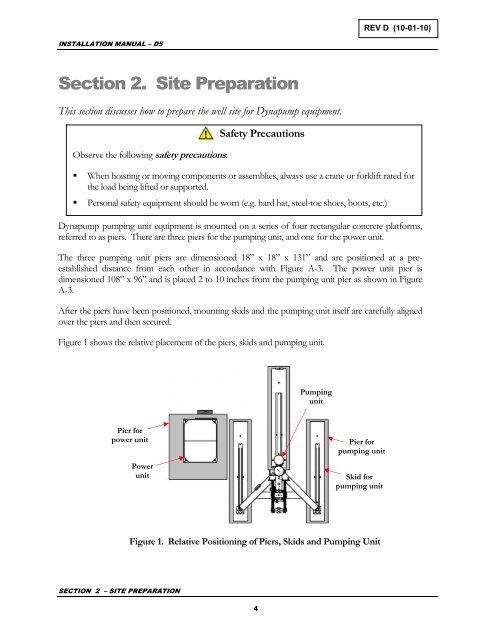
REV D (10-01-10)INSTALLATION MANUAL – D5Section 2. Site PreparationThis section discusses how to prepare the well site for Dynapump equipment.Observe the following safety precautions:Safety Precautions• When hoisting or moving components or assemblies, always use a crane or forklift rated forthe load being lifted or supported.• Personal safety equipment should be worn (e.g. hard hat, steel-toe shoes, boots, etc.)Dynapump pumping unit equipment is mounted on a series of four rectangular concrete platforms,referred to as piers. There are three piers for the pumping unit, and one for the power unit.The three pumping unit piers are dimensioned 18” x 18” x 131” and are positioned at a preestablisheddistance from each other in accordance with Figure A-3. The power unit pier isdimensioned 108” x 96” and is placed 2 to 10 inches from the pumping unit pier as shown in FigureA-3.After the piers have been positioned, mounting skids and the pumping unit itself are carefully alignedover the piers and then secured.Figure 1 shows the relative placement of the piers, skids and pumping unit.PumpingunitPier forpower unitPowerunitPier forpumping unitSkid forpumping unitFigure 1. Relative Positioning of Piers, Skids and Pumping UnitSECTION 2 – SITE PREPARATION4


