

Installation Manual - Model 5 - Tundra Process Solutions Ltd.
Installation Manual - Model 5 - Tundra Process Solutions Ltd.
Installation Manual - Model 5 - Tundra Process Solutions Ltd.

Create successful ePaper yourself
Turn your PDF publications into a flip-book with our unique Google optimized e-Paper software.
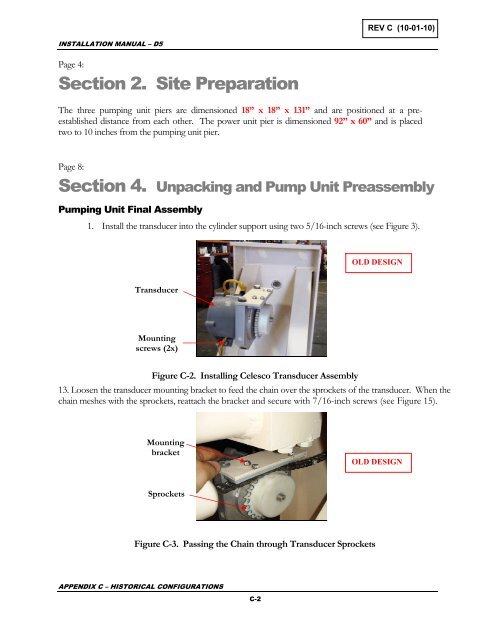
REV C (10-01-10)INSTALLATION MANUAL – D5Page 4:Section 2. Site PreparationThe three pumping unit piers are dimensioned 18” x 18” x 131” and are positioned at a preestablisheddistance from each other. The power unit pier is dimensioned 92” x 60” and is placedtwo to 10 inches from the pumping unit pier.Page 8:Section 4. Unpacking and Pump Unit PreassemblyPumping Unit Final Assembly1. Install the transducer into the cylinder support using two 5/16-inch screws (see Figure 3).OLD DESIGNTransducerMountingscrews (2x)Figure C-2. Installing Celesco Transducer Assembly13. Loosen the transducer mounting bracket to feed the chain over the sprockets of the transducer. When thechain meshes with the sprockets, reattach the bracket and secure with 7/16-inch screws (see Figure 15).MountingbracketOLD DESIGNSprocketsFigure C-3. Passing the Chain through Transducer SprocketsAPPENDIX C – HISTORICAL CONFIGURATIONSC-2


