

Installation Manual - Model 5 - Tundra Process Solutions Ltd.
Installation Manual - Model 5 - Tundra Process Solutions Ltd.
Installation Manual - Model 5 - Tundra Process Solutions Ltd.

You also want an ePaper? Increase the reach of your titles
YUMPU automatically turns print PDFs into web optimized ePapers that Google loves.
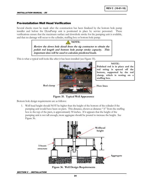
REV C (10-01-10)INSTALLATION MANUAL – D5Pre-installation Well Head VerificationSeveral checks must be made after the construction has been finalized by the bottom hole pumpinstaller and before the DynaPump unit is positioned in place by service personnel. Theseverifications ensure that the maximum surface and downhole stroke for the pumping unit is available,and that no damage will occur to the cylinder, stuffing box or bottom hole pump.NOTE:Review the down hole detail from the rig contractor to obtain thepolish rod length and bottom hole pump stroke capacity. Thisimportant data will be used to calculate predicted loads.This is what a typical well looks like after it has been installed (see Figure 35).NOTE:Polished rod is in place and therod string is spaced off thebottom, supported by the rodclamp, which is resting on astuffing box.Rod clampFlow linesBottom hole design requirements are as follows:Figure 35. Typical Well Appearance1. Well head height should NOT be higher than the height of the bottom of the cylinder if thepumping unit would have been on piers. This distance, shown as distance “A” from the stuffingbox to the top of the piers, is approximately 50 inches. If it appears that the height of thepumping unit is not tall enough, more aggregate should be poured to increase the height. SeeFigure 36.WellheadheightI-beamstructureAggregateSECTION 5 – INSTALLATIONFigure 36. Well Design Requirements24


