138914 Rev. Q 8/28/12Venting RequirementsThere are three types of venting configurations approvedfor use with this appliance:• Vertical Venting / Vertical Termination• Vertical Venting / Horizontal Termination• Horizontal Venting / Snorkel TerminationThis appliance is approved for use with the 4/6direct vent systems manufactured by the companieslisted on page 8. Use parts of one manufacturer only- DO NOT MIX VENT COMPONENTS FROM DIFFERENTMANUFACTURERS WITHIN THE SAME SYSTEM.Installation of any components not manufacturedor approved by Jøtul or failure to meet all clearancerequirements will void all warranties <strong>and</strong> couldresult in property damage or bodily injury.The approved vent configurations describedin this manual are derived from extensive testingunder controlled laboratory conditions. Gas applianceperformance can be negatively affected by variablespresent in the installation environment, i.e.; atmosphericpressure, strong prevailing winds, adjacentstructures <strong>and</strong> trees, snow accumulation, etc. Theseconditions should be taken into consideration by theinstaller <strong>and</strong> stove owner when planning the ventsystem design.Approved Vent ManufacturersThe Jøtul GF 370 DV stove is approved for installationwith direct vent chimney components supplied bythe following manufacturers:Simpson Dura-Vent, Inc.P.O. Box 1510Vacaville, CA 95696-1510 800-835-4429Selkirk Corporation1301 W. President George Bush Hwy, Suite 330Richardson, TX 75080-1139 800-992-8368American Metal Products (Amerivent)8601 Hacks Cross Rd.Olive Branch, MS 38654 800-423-4270Security Chimneys International Limited2125 Monterey, Laval, QuébecCanada, H7L 3T6 450-973-9999Metal-Fab, Inc.P.O. Box 1138Wichita, KS 67201 316-943-2351ICC, Inc.400 J-F Kennedy St. Jerome, QuebecCanada, J7Y 4B7 450-565 6336IMPORTANT• JOINT SEALINGREQUIREMENT:APPLY A 1/8” BEADOF HIGH-TEMPERA-TURE SEALANT ORMIL-PAC® TO THE MALESECTION OF THE INNERVENT PIPE. THE CE-Figure 6.MENT SHOULD FORMA SEAL BETWEEN THEINNER AND OUTER PIPES. SEE FIG. 5. SEE VENT MANUFAC-TURER’S INSTRUCTIONS.SEALANT• NEVER MODIFY ANY VENTING COMPONENT, ORUSE ANY DAMAGED VENTING PRODUCT.• THE GAS APPLIANCE AND VENT SYSTEM MUST BEVENTED DIRECTLY TO THE OUTSIDE OF THE BUILD-ING AND NEVER ATTACHED TO A CHIMNEY SERV-ING A SOLID FUEL OR GAS BURNING APPLIANCE.EACH DIRECT VENT GAS APPLIANCE MUST HAVEITS OWN SEPARATE VENT SYSTEM. COMMON VENTSYSTEMS ARE PROHIBITED.• IF VENTING SYSTEM IS DISASSEMBLED FOR ANYREASON, REINSTALL PER THE MANUFACTURER’SINSTRUCTIONS PROVIDED FOR THE INITIAL INSTAL-LATION.Vertical Venting <strong>and</strong> TerminationThe Jøtul GF 370 DV can be vertically vented througha roof or ceiling. Follow these guidelines• Steep roofs, nearby trees, or predominantly windyconditions, can promote poor draft or downdraft conditions. In such cases, an increase to theheight of the vent may improve performance.• If an offset or elbow is necessary in the verticalrise, the vent pipe must be supported every three feetto avoid excessive stress on the offsets. Use listed WallStraps from any of the approved vent suppliers.• A maximum of two 90° or four 45° elbows may beused in a vertical termination. Whenever possible,use 45° elbows instead of 90° elbows as theyoffer less restriction to the flow of flue gases <strong>and</strong>intake air.• A listed firestop is required at any floor penetration.The opening should be framed in accordingto the manufacturer’s instructions.• Always maintain a minimum 1" clearance from allsides of the vertical vent system to any combustiblematerial.• Minimum vertical termination height: 6 ft. ofvent pipe.8
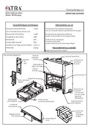
138914 Rev. Q 8/28/1218”.min.Horizontal Overhang18”.min.Cap Adaptor-#991 Vertical Termination CapExhaust GasVertical WallTerminationCap18” min.Lowest DischargeOpeningIntake AirFigure 7. Minimum roof penetrationheight <strong>and</strong> clearancefrom adjacent surfaces - verticaltermination.4” Flex Pipenot includedin kitSupport/WallThimble Cover• IT IS NECESSARY to add restriction to a vertical ventinstallation to compensate for excessive draft. Seepage 13; Exhaust Restriction Adjustment.• GAS VENT HEIGHT: In no case shall any dischargeopening on the cap be less than 18” (457 mm) horizontallyfrom the roof surface. See fig. 7.• Maximum Vent Height: 35 ft. above the appliance.Use St<strong>and</strong>ardSimpson Dura-Vent GS Pipefrom stove tothimbleMasonry or Prefabricated ChimneyConversionThe GF 370 DV is approved for use with direct ventchimney conversion kits in a masonry chimney ora prefabricated solid fuel listed chimney. These areavailable from most of the manufacurer’s listed onpage 8.The following installation requirements must befollowed:1. Use the restrictor zone guidelines in the VentWindow Diagram, fig. 17. In masonry chimney, afireclay liner or listed steel liner, must be containedwithin the entire length of the chimney.3. Overall venting should not exceed 35 ft. (10.67 m).4. The liner must have an inside dimension of 6”round or greater.5. Prefabricated chimneys must be UL 103 or ULCS-629 listed <strong>and</strong> have a minimum INSIDE diameterof 6 inches, (150 mm). Prefabricated chimneysmust be listed for the specific manufacturer’sconversion kit.Figure 8. Vent System through a masonry chimneyusing the Simpson Dura-Vent Chimney ConversionKit 46DVA-KMC <strong>and</strong> 46DVA-KCT components. Othermanufacturers use similar designs. Conversion kitsare also available for use with listed prefabricatedchimneys.IMPORTANT NOTICETHE USE OF AN EXISTING CHIMNEY AS AN AIRINTAKE IS NOT COVERED UNDER THE ANSIZ21.88-1999-CSA 2.33-M99 TEST METHODSAND RESULTING ITS/WHI PRODUCT CERTI-FICATION. THE CODE AUTHORITY HAVINGJURISDICTION MUST BE CONSULTED PRIORTO PROCEEDING WITH THIS INSTALLATIONMETHOD.9