138914 Rev. Q 8/28/123.0 Safety Information• Due to the high operating temperatures this applianceshould be located out of traffic <strong>and</strong> away fromfurniture, draperies, etc. Maintain proper clearance tocombustible mantels <strong>and</strong> fireplace trim.• Children <strong>and</strong> adults should be alerted to the hazardsof high surface temperatures <strong>and</strong> should stay away toavoid burns or clothing ignition.• Enfants et adultes doivent être avertis des dangers destempératures de surface élevées et devraient rester àl’écart pour éviter les brûlures ou l’inflammation desvêtements.• Young children should be supervised while they arein the same room as the appliance. Toddlers, youngchildren <strong>and</strong> others may be susceptible to accidentalcontact burns. A physical barrier, such as a childguard, is recommended to be used if there are at-riskindividuals in the house. To restrict access to a fireplaceor stove, install an adjustable safety gate to keeptoddlers, young children <strong>and</strong> other at-risk individualsout of the room <strong>and</strong> away from hot surfaces.• Les jeunes enfants doivent être surveillés pendantqu’ils sont dans la même pièce que l’appareil. Les toutpetits,les jeunes enfants et d’autres peuvent être sensiblesaux brûlures par contact accidentel. Une barrièrephysique, comme un garde de l’enfant, est recomm<strong>and</strong>épour être utilisé si il ya des personnes à risque dansla maison. Pour restreindre l’accès à une cheminée ouun poêle, installer une barrière de sécurité réglablepour garder les tout-petits, les jeunes enfants et autrespersonnes à risque à se sortir de la salle et à l’écart dessurfaces chaudes.• Any safety screen or guard removed for servicing anappliance must be replaced prior to operating the appliance.• Tout écran ou grille de protection pour l’entretien d’un appareildoit être remplacé avant de faire fonctionner l’appareil.• Clothing or other flammable materials should not beplaced on or near the fireplace.• Surveiller les enfants. Garder les vêtements, lesmeubles, l’essence ou autres liquides à vapeurinflammables lin de l’appareil.• Never allow anyone to use the fireplace if they areunfamiliar with its operation.• NEVER store or use gasoline or any other flammablevapors or liquids in the vicinity of the fireplace.• Never burn any solid materials (wood, cardboard,paper, coal, etc.) in this gas fireplace. Use with naturalgas or propane fuel ONLY.• Do not slam or strike the glass panel.• This appliance is NOT for use with aftermarket glassdoors. This appliance is approved for use only withthe surround panel options listed on page 4 of thismanual.Cet appareil ne sert pas avec des portes en verre demarché des accessoires. Cet appareil est approuvépour l’usage seulement avec les revêtements deporte, entoure les options de panneau et en verrede panneau énumérées à la page 3 de ce manuel.• Wear gloves <strong>and</strong> safety glasses while performingmaintenance procedures.WARNING!Shock Hazard. Can cause severe injury or death.This appliance is powered by line voltage.Do not try to repair the components in thisappliance. In no way are the componentenclosures to be tampered with or opened.Disconnect from line voltage duringinstallation or performing any maintenance.ATTENTION!• Shut off the main gas supply to theappliance during battery replacement to thereceiver or burner control.• Always shut off the main gas supply to theappliance during inspection, maintenance,or cleaning.Electrical Hazards• Be aware of electrical wiring locations when cuttingholes in walls <strong>and</strong> ceilings for termination.• This appliance power supply must be electricallygrounded in accordance with local codesor, in the absence of local codes, with the currentANSI/NFPA 70, National Electrical Codeor CSA C22.1-Canadian Electrical Code.• This appliance power supply incorporates athree-prong (grounding) plug for protectionagainst shock hazard <strong>and</strong> should be pluggeddirectly into a properly grounded three-prongreceptacle. DO NOT CUT OR REMOVE THEGROUNDING PRONG FROM THE PLUG.• Do not disconnect the lamp <strong>and</strong> fan powercords from the appliance power supply (FanControl Module). Use the rocker switch tocontrol power to these parts.• Always disconnect (unplug) the main powersupply from its outlet when performing routineservice on this appliance.6
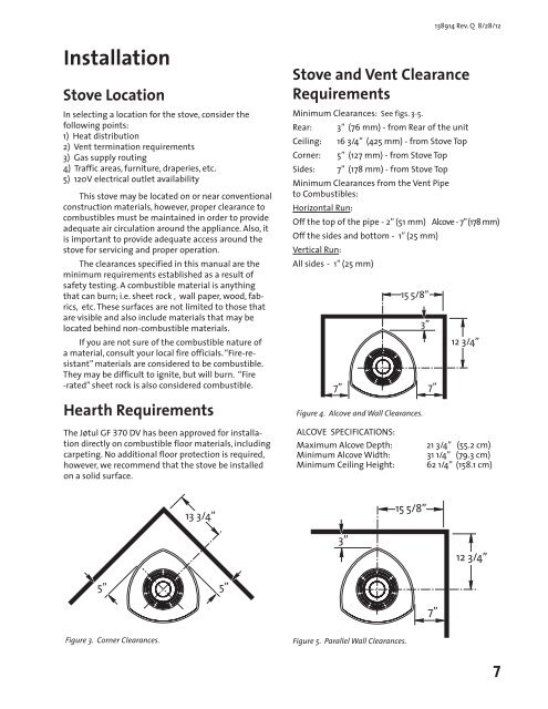
138914 Rev. Q 8/28/12InstallationStove LocationIn selecting a location for the stove, consider thefollowing points:1) Heat distribution2) Vent termination requirements3) Gas supply routing4) Traffic areas, furniture, draperies, etc.5) 120V electrical outlet availabilityThis stove may be located on or near conventionalconstruction materials, however, proper clearance tocombustibles must be maintained in order to provideadequate air circulation around the appliance. Also, itis important to provide adequate access around thestove for servicing <strong>and</strong> proper operation.The clearances specified in this manual are theminimum requirements established as a result ofsafety testing. A combustible material is anythingthat can burn; i.e. sheet rock , wall paper, wood, fabrics,etc. These surfaces are not limited to those thatare visible <strong>and</strong> also include materials that may belocated behind non-combustible materials.If you are not sure of the combustible nature ofa material, consult your local fire officials. “Fire-resistant”materials are considered to be combustible.They may be difficult to ignite, but will burn. “Fire-rated” sheet rock is also considered combustible.Hearth RequirementsThe Jøtul GF 370 DV has been approved for installationdirectly on combustible floor materials, includingcarpeting. No additional floor protection is required,however, we recommend that the stove be installedon a solid surface.Stove <strong>and</strong> Vent ClearanceRequirementsMinimum Clearances: See figs. 3-5.Rear:Ceiling:Corner:Sides:3” (76 mm) - from Rear of the unit16 3/4” (425 mm) - from Stove Top5” (127 mm) - from Stove Top7” (178 mm) - from Stove TopMinimum Clearances from the Vent Pipeto Combustibles:Horizontal Run:Off the top of the pipe - 2” (51 mm) Alcove - 7” (178 mm)Off the sides <strong>and</strong> bottom - 1” (25 mm)Vertical Run:All sides - 1” (25 mm)7”ALCOVE SPECIFICATIONS:Maximum Alcove Depth:Minimum Alcove Width:Minimum Ceiling Height:15 5/8”Figure 4. Alcove <strong>and</strong> Wall Clearances.3”7”12 3/4”21 3/4” (55.2 cm)31 1/4” (79.3 cm)62 1/4” (158.1 cm)13 3/4”15 5/8”3”12 3/4”5”5”7”Figure 3. Corner Clearances. Corner InstallationFigure 5. Parallel Wall Clearances.7