Manual - Jøtul stoves and fireplaces
Manual - Jøtul stoves and fireplaces
Manual - Jøtul stoves and fireplaces

Create successful ePaper yourself
Turn your PDF publications into a flip-book with our unique Google optimized e-Paper software.
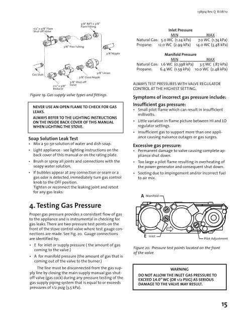
138914 Rev. Q 8/28/121/2” x 3/8” FlareShut-off Valve3/8” Flex Tubing3/8” NPT x 3/8”Flare FittingInlet PressureMINMAXNatural Gas: 5.0 WC (1.24 kPa) 7.0 WC (1.74 kPa)Propane: 12.0 WC (2.99 kPa) 14.0 WC (3.48 kPa)Gas Stub1/2” x 3/8”Reducer3/8” Shut-offValve3/8” Close Nipple3/8” UnionFigure 19. Gas supply valve types <strong>and</strong> fittings.Soap Solution Leak Test• Mix a 50-50 solution of water <strong>and</strong> dish soap.3/8”NippleNEVER USE AN OPEN FLAME TO CHECK FOR GASLEAKS.ALWAYS REFER TO THE LIGHTING INSTRUCTIONSON THE INSIDE BACK COVER OF THIS MANUALWHEN LIGHTING THE STOVE.• Light appliance - see lighting instructions on theback cover of this manual or on the rating plate.• Brush or spray all joints <strong>and</strong> connections with thesoapy water solution.• If bubbles appear at any connection or seam or agas odor is detected, immediately turn gas controlknob to the OFF position.Tighten or reconnect the leaking joint <strong>and</strong> retestfor any gas leaks.4. Testing Gas PressureProper gas pressure provides a consistent flow of gasto the appliance <strong>and</strong> is instrumental in checking forgas leaks. There are two pressure test points on thefront of the stove control valve where test gauge connectionsare made. See Fig. 20. Gauge connectionsare identified by:• E for inlet or supply pressure ( the amount of gascoming to the valve.)• A for manifold pressure (the amount of gas that iscoming out of the valve to the burner.)The line must be disconnected from the gas supplyline by closing the main supply manual gas shutoffvalve (gas cock) during any pressure testing of thegas supply piping system that is equal to or exceedspressures of 1/2 psig (3.5 kPa).Manifold PressureMINMAXNatural Gas: 1.6 WC (0.398 kPa) 3.5 WC (.87 kPa)Propane: 6.4 WC (1.59 kPa) 10.0 WC (2.48 kPa)ALWAYS TEST PRESSURES WITH VALVE REGULATORCONTROL AT THE HIGHEST SETTING.Symptoms of incorrect gas pressure include:Insufficient gas pressure:• Small pilot flame which can result in insufficientmillivolts.• Little variation in flame picture between HI <strong>and</strong> LOregulator settings.• Insufficient gas to support more than one appliancecausing nuisance outages or gas surges.Excessive gas pressure:• Permanent damage to valve causing complete applianceshut down.• Too large a pilot flame resulting in overheating ofthe power generator <strong>and</strong> consequent shut down.• Sooting due to impingement <strong>and</strong>/or incorrect fuelto air mix.AEManifoldInletFigure 20. Pressure test points located on the frontof the valve.WARNINGPilot AdjustmentDO NOT ALLOW THE INLET GAS PRESSURE TOEXCEED 14.0” WC (OR 1/2 PSIG) AS SERIOUSDAMAGE TO THE VALVE MAY RESULT.15