Manual - Jøtul stoves and fireplaces
Manual - Jøtul stoves and fireplaces
Manual - Jøtul stoves and fireplaces

You also want an ePaper? Increase the reach of your titles
YUMPU automatically turns print PDFs into web optimized ePapers that Google loves.
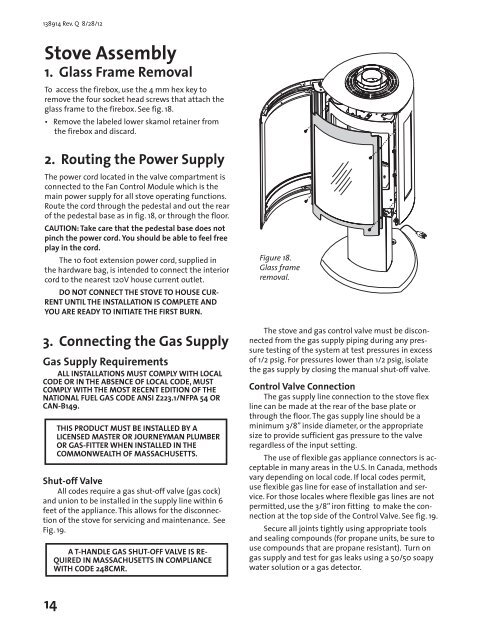
138914 Rev. Q 8/28/12Stove Assembly1. Glass Frame RemovalTo access the firebox, use the 4 mm hex key toremove the four socket head screws that attach theglass frame to the firebox. See fig. 18.• Remove the labeled lower skamol retainer fromthe firebox <strong>and</strong> discard.2. Routing the Power SupplyThe power cord located in the valve compartment isconnected to the Fan Control Module which is themain power supply for all stove operating functions.Route the cord through the pedestal <strong>and</strong> out the rearof the pedestal base as in fig. 18, or through the floor.CAUTION: Take care that the pedestal base does notpinch the power cord. You should be able to feel freeplay in the cord.The 10 foot extension power cord, supplied inthe hardware bag, is intended to connect the interiorcord to the nearest 120V house current outlet.DO NOT CONNECT THE STOVE TO HOUSE CUR-RENT UNTIL THE INSTALLATION IS COMPLETE ANDYOU ARE READY TO INITIATE THE FIRST BURN.3. Connecting the Gas SupplyGas Supply RequirementsALL INSTALLATIONS MUST COMPLY WITH LOCALCODE OR IN THE ABSENCE OF LOCAL CODE, MUSTCOMPLY WITH THE MOST RECENT EDITION OF THENATIONAL FUEL GAS CODE ANSI Z223.1/NFPA 54 ORCAN-B149.THIS PRODUCT MUST BE INSTALLED BY ALICENSED MASTER OR JOURNEYMAN PLUMBEROR GAS-FITTER WHEN INSTALLED IN THECOMMONWEALTH OF MASSACHUSETTS.Shut-off ValveAll codes require a gas shut-off valve (gas cock)<strong>and</strong> union to be installed in the supply line within 6feet of the appliance. This allows for the disconnectionof the stove for servicing <strong>and</strong> maintenance. SeeFig. 19.A T-HANDLE GAS SHUT-OFF VALVE IS RE-QUIRED IN MASSACHUSETTS IN COMPLIANCEWITH CODE 248CMR.Figure 18.Glass frameremoval.The stove <strong>and</strong> gas control valve must be disconnectedfrom the gas supply piping during any pressuretesting of the system at test pressures in excessof 1/2 psig. For pressures lower than 1/2 psig, isolatethe gas supply by closing the manual shut-off valve.Control Valve ConnectionThe gas supply line connection to the stove flexline can be made at the rear of the base plate orthrough the floor. The gas supply line should be aminimum 3/8” inside diameter, or the appropriatesize to provide sufficient gas pressure to the valveregardless of the input setting.The use of flexible gas appliance connectors is acceptablein many areas in the U.S. In Canada, methodsvary depending on local code. If local codes permit,use flexible gas line for ease of installation <strong>and</strong> service.For those locales where flexible gas lines are notpermitted, use the 3/8” iron fitting to make the connectionat the top side of the Control Valve. See fig. 19.Secure all joints tightly using appropriate tools<strong>and</strong> sealing compounds (for propane units, be sure touse compounds that are propane resistant). Turn ongas supply <strong>and</strong> test for gas leaks using a 50/50 soapywater solution or a gas detector.14