Manual - Jøtul stoves and fireplaces
Manual - Jøtul stoves and fireplaces
Manual - Jøtul stoves and fireplaces

You also want an ePaper? Increase the reach of your titles
YUMPU automatically turns print PDFs into web optimized ePapers that Google loves.
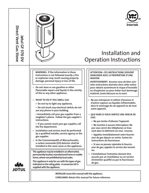
Jøtul GF 370 DVDirect Vent Gas StoveInstallation <strong>and</strong>Operation InstructionsWARNING: If the information in theseinstructions is not followed exactly, a fireor explosion may result causing propertydamage, personal injury or loss of life.– Do not store or use gasoline or otherflammable vapors <strong>and</strong> liquids in the vicinityof this or any other appliance.– WHAT TO DO IF YOU SMELL GAS• Do not try to light any appliance.• Do not touch any electrical switch; do notuse any phone in your building.• Immediately call your gas supplier from aneighbor’s phone. Follow the gas supplier’sinstructions.• If you cannot reach your gas supplier, callthe fire department.– Installation <strong>and</strong> service must be performedby a qualified installer, service agency or thegas supplier.– In the Commonwealth of Massachusetts,a carbon monoxide (CO) detector shall beinstalled in the same room as the appliance.This appliance may be installed in an aftermarket,permanently located, manufactured home or mobilehome, where not prohibited by local codes.This appliance is only for use with the types of gasindicated on the rating plate. A conversion kit issupplied with the appliance.ATTENTION : CES INSTRUCTIONS DOIVENTDEMUERER AVEC LE PROPRIÉTERE D’UNEMAISON.AVERTISSEMENT: Assurez-vous de bien suivrelesinstructions données dans cette noticepour réduire auninimum le risque d’incendieou d’explosion ou pour éviter tout dommagematériel, toute blessure ou la mort.– Ne pas entreposer ni utiliser d’essence nid’autres vapeurs ou liquides inflammablesdans le voisinage de cet appareil ou de toutautre appareil.– QUE FAIRE SI VOUS SENTEZ UNE ODEUR DEGAZ:• Ne pas tenter d’allumer l’appareil.• Ne touchez à aucum interrupteur. Nepas vous servir des téléphones se trouvantdans le bâtiment où vous trouvez.• Appelez immédiatement votre fournisseurde gaz depuis un voisin. Suivez lesinstructions du fournisseur.• Si vou ne pouvez rejoindre le fournisseurde gaz, appelez le service des incendies.– L’installatione l’entretien doivent êtreassurés par un installateur ou un serviced’entretien qualifié ou par le fournisseurde gaz.INSTALLER: Leave this manual with the appliance.CONSUMER: Retain this manual for future reference.
138914 Rev. Q 8/28/122!!Suggested Tools for Installation <strong>and</strong> Service• External regulator (for Propane only)• Piping which complies with local code• <strong>Manual</strong> shut-off valve -T-H<strong>and</strong>le required in Massachusetts• Sediment trap - if required by code• Tee joint• Pipe wrench• Pipe sealant• 10 mm open end wrench• 1/2”, 7/16” open end wrench• Phillips head screwdriver• Flat head screwdriver• 1/4” nut driverWARNINGHOT GLASS WILLCAUSE BURNS.DO NOT TOUCH GLASSUNTIL COOLED.NEVER ALLOW CHILDRENTO TOUCH GLASS.AVERTISSEMENTUne surface vitrée chaudepeut causer des brûlures.Laisser refroidir la surface vitréeavant d’y toucher.Ne perettex jamais à unenfantde toucher la surface vitrée.THIS OWNER’S MANUAL PROVIDES INFORMATION TOENSURE SAFE INSTALLATION AND EFFICIENT, DEPENDABLEOPERATION OF YOUR FIREPLACE INSERT. PLEASE READTHESE INSTRUCTIONS IN THEIR ENTIRETY AND MAKE THEMAVAILABLE TO ANYONE USING OR SERVICING THIS GASINSERT.DO NOT ATTEMPT TO ALTER OR MODIFY THE CONSTRUCTIONOF THIS APPLIANCE OR ITS COMPONENTS. ANYMODIFICATION OR ALTERATION WILL VOID THE WARRANTY,CERTIFICATION AND LISTING OF THIS APPLIANCE.THIS HEATER MUST BE INSTALLED AND MAINTAINED BY AQUALIFIED SERVICE AGENCY.• Work Gloves• Safety glasses• Torx T-20 screwdriver• Tin snipsInstallation Requirements for theCommonwealth of MassachusettsTHIS PRODUCT MUST BE INSTALLED BY ALICENSED MASTER OR JOURNEYMAN PLUMBEROR GAS-FITTER WHEN INSTALLED IN THECOMMONWEALTH OF MASSACHUSETTS.1. If there is not one already present, on eachfloor level where there are bedroom(s), acarbon monoxide detector <strong>and</strong> alarm shallbe placed in the living area outside thebedroom(s). The carbon monoxide detectorshall comply with NFPA 720 (2005 Edition).2. A carbon monoxide detector shall:a) Be located in the room that houses theappliance or equipment;b) Be either hard-wired or battery poweredor both; <strong>and</strong>c) Shall comply with NFPA 720 (2002Edition).3. A Product-approved vent terminal must beused, <strong>and</strong> if applicable, a Product-approvedair intake must be used. Installationshall be in strict compliance with themanufacturer’s instructions. A copy ofthe installation instructions must remainwith the appliance or equipment at thecompletion of the installation.We recommend thatour gas products beinstalled <strong>and</strong> serviced byprofessionals who arecertified in the U.S. bythe National FireplaceInstitute® (NFI) as NFI GasSpecialists.72.41%Jøtul GF 370 DV
138914 Rev. Q 8/28/12Table of ContentsInstallation & Service Tools ..................2Specifications................................................... 4General Information.......................................5Safety Information ........................................ 6InstallationHearth Requirements ..........................7Clearances...............................................7Vent RequirementsApproved Vent Manufacturers.......... 8Vertical Termination............................ 8Masonry Chimney Conversion.......... 9Horizontal Termination......................10Vent Termination Clearances.............11Vent Restriction Adjustments.......... 12Vent Termination Diagram................ 13Stove Assembly1. Glass Frame Removal ...................142. Routing the Power Supply ..........143. Gas Connection..............................144. Gas Pressure................................... 155. Fuel Conversion..............................166. High Altitude Adjustment..........187. Skamol Panel Installation............198. Reflective Panel Installation.......199. River Rock Installation..................1910. StarFire Glass Installation...........1911. Log Set Installation......................2012. Outer Decorative Glass Panels... 2113. System Check ............................... 2214. Flame Picture Adjustment...........23OperationSystem Overview ............................... 24Control Functions................................25Wiring Diagrams................................. 28MaintenanceAnnual Cleaning.................................30.Glass Replacement.............................30Battery Replacement ......................... 31Accent Lamp Replacement ............... 31Illustrated Replacement Parts........... 32 - 35AppendixMobile Home Installation................ 36Correct Optional Flame Pictures .... 36Waranty Statement.......................................37Lighting Instructions .................................. 39Unpacking the Stove1. Before beginning the installation, inspect the stovefor shipping damage <strong>and</strong> immediately report anyevidence of damage to your dealer.2. Confirm stove contents.The Jøtul GF 370 DV includes the following looseitems shipped in the Miscellaneous Hardware bag;• 4 mm hex key - used to remove thefront glass panel for access to the firebox.• Remote Control Transmitter• Remote Control Wall Mount Bracket• Extension Power Cord• M6 x 12 mm hex bolts, 4 - used withOuter Decorative Glass Panels.• Propane Fuel Conversion Kit 1568003. Confirm Firebox Components.The firebox accessories have been packed inseparate boxes, <strong>and</strong> will include one or more of thefollowing items:• Traditional Log Set 156789• StarFire Glass 156815, Clear or 157342, Black• River Rocks 157428• Skamol Panels 156816• Reflective Glass Panels 156817• Tumbled Stones 1572294. Remove Pallet Screw. See fig. 1.Figure 1.Pallet screw location3
138914 Rev. Q 8/28/12General InformationTHIS HEATER MUST BE INSTALLED AND MAIN-TAINED BY A QUALIFIED SERVICE AGENCY.DO NOT ATTEMPT TO ALTER OR MODIFY THECONSTRUCTION OF THIS APPLIANCE OR ITS COM-PONENTS. ANY MODIFICATION OR ALTERATIONWILL VOID THE WARRANTY, CERTIFICATION ANDLISTING OF THIS APPLIANCE.WARNING: FAILURE TO POSITION THE PARTS INACCORDANCE WITH THE DIAGRAMS HEREIN ORFAILURE TO USE ONLY PARTS SPECIFICALLY AP-PROVED WITH THIS APPLIANCE MAY RESULT INPROPERTY DAMAGE OR PERSONAL INJURY.IMPORTANT: SAVE THESE INSTRUCTIONS.1. The installation <strong>and</strong> repair of this appliance mustbe done by a qualified service person. Failure toproperly install <strong>and</strong> maintain this heater could resultin an unsafe or hazardous installation, whichmay result in a fire, explosion, property damage,personal injury or loss of life.2. This appliance should be inspected before use <strong>and</strong>at least annually. More frequent cleaning maybe required due to excessive lint from carpeting,bedding material, etc. It is imperative that controlcompartments, burners <strong>and</strong> circulating air passagewaysof the appliance be kept clean.`S’assurer que le bruleur et le compartiment descomm<strong>and</strong>es sont propres. Voir les instructionsd’installation et d’utilisation qui accompagnentl’appareil.3. This appliance may be installed in an aftermarketpermanently located, manufactured (mobile)home, where not prohibited by local codes.This appliance is only for use with the type(s) ofgas indicated on the rating plate. This appliance isnot convertible for use with other gases, unless acertified kit is used.Cetappareil peut être installé dans un maisonpréfabriquée (mobile) déjà installée à demeure siles règlements locaux le permettent.Cet appareil doit être utilisé uniquement avec lestypes de gas indiqués sur la plaque signalétique.Ne pas l’utiliser avec d’autres gas sauf si un kitdeconversion certifié est installé.4. The installation must conform to local codes. Yourlocal Jøtul authorized dealer can assist you in determiningwhat is required in your area for a safe<strong>and</strong> legal installation. Some areas require a permitto install a gas burning appliance. Always consultyour local building inspector or authority havingjurisdiction to determine what regulations apply inyour area.In the absence of local codes, the installation requirementsmust comply with the current Nationalcodes. In the U.S., these requirements are establishedin the National Fuel Code, ANSI Z223.1.(NFPA54). In Canada, the codes have been established inCAN/CGA B149 Fuel Installation Code.Installer l’appareil selon les codes ou reglementslocaux, ou, en l’absence de tels reglements, selonles Codes d’installation CAN/CGA-B149.5. Do not operate this fireplace if any part of it hasbeen under water..Immediately call a qualified service technician toinspect the heater <strong>and</strong> to replace any part of thecontrol system <strong>and</strong> any gas control which has beenunder water.Ne pas se servir de cet appareil s’il a ete’ plongedans l’eau, completement ou en partie. Appelerun technicien qualifie pour inspecter l’appareil etremplacer toute partie du syste’me de controle ettoute comm<strong>and</strong>e qui ont ete plonges dans l’eau.6. Do not operate the fireplace with the glass frontremoved, cracked or broken. Replacement of theglass should be done by a licensed or qualified serviceperson. Only remove glass for routine service.Always h<strong>and</strong>le glass carefully.Pour utilisation avec les portes en verre cerifiersaved l’appareil seulemend ou. Ne pas utiliser avecdes portes on verre.7. Notify your insurance company before procedingwith installation of this fireplace.5
138914 Rev. Q 8/28/123.0 Safety Information• Due to the high operating temperatures this applianceshould be located out of traffic <strong>and</strong> away fromfurniture, draperies, etc. Maintain proper clearance tocombustible mantels <strong>and</strong> fireplace trim.• Children <strong>and</strong> adults should be alerted to the hazardsof high surface temperatures <strong>and</strong> should stay away toavoid burns or clothing ignition.• Enfants et adultes doivent être avertis des dangers destempératures de surface élevées et devraient rester àl’écart pour éviter les brûlures ou l’inflammation desvêtements.• Young children should be supervised while they arein the same room as the appliance. Toddlers, youngchildren <strong>and</strong> others may be susceptible to accidentalcontact burns. A physical barrier, such as a childguard, is recommended to be used if there are at-riskindividuals in the house. To restrict access to a fireplaceor stove, install an adjustable safety gate to keeptoddlers, young children <strong>and</strong> other at-risk individualsout of the room <strong>and</strong> away from hot surfaces.• Les jeunes enfants doivent être surveillés pendantqu’ils sont dans la même pièce que l’appareil. Les toutpetits,les jeunes enfants et d’autres peuvent être sensiblesaux brûlures par contact accidentel. Une barrièrephysique, comme un garde de l’enfant, est recomm<strong>and</strong>épour être utilisé si il ya des personnes à risque dansla maison. Pour restreindre l’accès à une cheminée ouun poêle, installer une barrière de sécurité réglablepour garder les tout-petits, les jeunes enfants et autrespersonnes à risque à se sortir de la salle et à l’écart dessurfaces chaudes.• Any safety screen or guard removed for servicing anappliance must be replaced prior to operating the appliance.• Tout écran ou grille de protection pour l’entretien d’un appareildoit être remplacé avant de faire fonctionner l’appareil.• Clothing or other flammable materials should not beplaced on or near the fireplace.• Surveiller les enfants. Garder les vêtements, lesmeubles, l’essence ou autres liquides à vapeurinflammables lin de l’appareil.• Never allow anyone to use the fireplace if they areunfamiliar with its operation.• NEVER store or use gasoline or any other flammablevapors or liquids in the vicinity of the fireplace.• Never burn any solid materials (wood, cardboard,paper, coal, etc.) in this gas fireplace. Use with naturalgas or propane fuel ONLY.• Do not slam or strike the glass panel.• This appliance is NOT for use with aftermarket glassdoors. This appliance is approved for use only withthe surround panel options listed on page 4 of thismanual.Cet appareil ne sert pas avec des portes en verre demarché des accessoires. Cet appareil est approuvépour l’usage seulement avec les revêtements deporte, entoure les options de panneau et en verrede panneau énumérées à la page 3 de ce manuel.• Wear gloves <strong>and</strong> safety glasses while performingmaintenance procedures.WARNING!Shock Hazard. Can cause severe injury or death.This appliance is powered by line voltage.Do not try to repair the components in thisappliance. In no way are the componentenclosures to be tampered with or opened.Disconnect from line voltage duringinstallation or performing any maintenance.ATTENTION!• Shut off the main gas supply to theappliance during battery replacement to thereceiver or burner control.• Always shut off the main gas supply to theappliance during inspection, maintenance,or cleaning.Electrical Hazards• Be aware of electrical wiring locations when cuttingholes in walls <strong>and</strong> ceilings for termination.• This appliance power supply must be electricallygrounded in accordance with local codesor, in the absence of local codes, with the currentANSI/NFPA 70, National Electrical Codeor CSA C22.1-Canadian Electrical Code.• This appliance power supply incorporates athree-prong (grounding) plug for protectionagainst shock hazard <strong>and</strong> should be pluggeddirectly into a properly grounded three-prongreceptacle. DO NOT CUT OR REMOVE THEGROUNDING PRONG FROM THE PLUG.• Do not disconnect the lamp <strong>and</strong> fan powercords from the appliance power supply (FanControl Module). Use the rocker switch tocontrol power to these parts.• Always disconnect (unplug) the main powersupply from its outlet when performing routineservice on this appliance.6
138914 Rev. Q 8/28/12InstallationStove LocationIn selecting a location for the stove, consider thefollowing points:1) Heat distribution2) Vent termination requirements3) Gas supply routing4) Traffic areas, furniture, draperies, etc.5) 120V electrical outlet availabilityThis stove may be located on or near conventionalconstruction materials, however, proper clearance tocombustibles must be maintained in order to provideadequate air circulation around the appliance. Also, itis important to provide adequate access around thestove for servicing <strong>and</strong> proper operation.The clearances specified in this manual are theminimum requirements established as a result ofsafety testing. A combustible material is anythingthat can burn; i.e. sheet rock , wall paper, wood, fabrics,etc. These surfaces are not limited to those thatare visible <strong>and</strong> also include materials that may belocated behind non-combustible materials.If you are not sure of the combustible nature ofa material, consult your local fire officials. “Fire-resistant”materials are considered to be combustible.They may be difficult to ignite, but will burn. “Fire-rated” sheet rock is also considered combustible.Hearth RequirementsThe Jøtul GF 370 DV has been approved for installationdirectly on combustible floor materials, includingcarpeting. No additional floor protection is required,however, we recommend that the stove be installedon a solid surface.Stove <strong>and</strong> Vent ClearanceRequirementsMinimum Clearances: See figs. 3-5.Rear:Ceiling:Corner:Sides:3” (76 mm) - from Rear of the unit16 3/4” (425 mm) - from Stove Top5” (127 mm) - from Stove Top7” (178 mm) - from Stove TopMinimum Clearances from the Vent Pipeto Combustibles:Horizontal Run:Off the top of the pipe - 2” (51 mm) Alcove - 7” (178 mm)Off the sides <strong>and</strong> bottom - 1” (25 mm)Vertical Run:All sides - 1” (25 mm)7”ALCOVE SPECIFICATIONS:Maximum Alcove Depth:Minimum Alcove Width:Minimum Ceiling Height:15 5/8”Figure 4. Alcove <strong>and</strong> Wall Clearances.3”7”12 3/4”21 3/4” (55.2 cm)31 1/4” (79.3 cm)62 1/4” (158.1 cm)13 3/4”15 5/8”3”12 3/4”5”5”7”Figure 3. Corner Clearances. Corner InstallationFigure 5. Parallel Wall Clearances.7
138914 Rev. Q 8/28/12Venting RequirementsThere are three types of venting configurations approvedfor use with this appliance:• Vertical Venting / Vertical Termination• Vertical Venting / Horizontal Termination• Horizontal Venting / Snorkel TerminationThis appliance is approved for use with the 4/6direct vent systems manufactured by the companieslisted on page 8. Use parts of one manufacturer only- DO NOT MIX VENT COMPONENTS FROM DIFFERENTMANUFACTURERS WITHIN THE SAME SYSTEM.Installation of any components not manufacturedor approved by Jøtul or failure to meet all clearancerequirements will void all warranties <strong>and</strong> couldresult in property damage or bodily injury.The approved vent configurations describedin this manual are derived from extensive testingunder controlled laboratory conditions. Gas applianceperformance can be negatively affected by variablespresent in the installation environment, i.e.; atmosphericpressure, strong prevailing winds, adjacentstructures <strong>and</strong> trees, snow accumulation, etc. Theseconditions should be taken into consideration by theinstaller <strong>and</strong> stove owner when planning the ventsystem design.Approved Vent ManufacturersThe Jøtul GF 370 DV stove is approved for installationwith direct vent chimney components supplied bythe following manufacturers:Simpson Dura-Vent, Inc.P.O. Box 1510Vacaville, CA 95696-1510 800-835-4429Selkirk Corporation1301 W. President George Bush Hwy, Suite 330Richardson, TX 75080-1139 800-992-8368American Metal Products (Amerivent)8601 Hacks Cross Rd.Olive Branch, MS 38654 800-423-4270Security Chimneys International Limited2125 Monterey, Laval, QuébecCanada, H7L 3T6 450-973-9999Metal-Fab, Inc.P.O. Box 1138Wichita, KS 67201 316-943-2351ICC, Inc.400 J-F Kennedy St. Jerome, QuebecCanada, J7Y 4B7 450-565 6336IMPORTANT• JOINT SEALINGREQUIREMENT:APPLY A 1/8” BEADOF HIGH-TEMPERA-TURE SEALANT ORMIL-PAC® TO THE MALESECTION OF THE INNERVENT PIPE. THE CE-Figure 6.MENT SHOULD FORMA SEAL BETWEEN THEINNER AND OUTER PIPES. SEE FIG. 5. SEE VENT MANUFAC-TURER’S INSTRUCTIONS.SEALANT• NEVER MODIFY ANY VENTING COMPONENT, ORUSE ANY DAMAGED VENTING PRODUCT.• THE GAS APPLIANCE AND VENT SYSTEM MUST BEVENTED DIRECTLY TO THE OUTSIDE OF THE BUILD-ING AND NEVER ATTACHED TO A CHIMNEY SERV-ING A SOLID FUEL OR GAS BURNING APPLIANCE.EACH DIRECT VENT GAS APPLIANCE MUST HAVEITS OWN SEPARATE VENT SYSTEM. COMMON VENTSYSTEMS ARE PROHIBITED.• IF VENTING SYSTEM IS DISASSEMBLED FOR ANYREASON, REINSTALL PER THE MANUFACTURER’SINSTRUCTIONS PROVIDED FOR THE INITIAL INSTAL-LATION.Vertical Venting <strong>and</strong> TerminationThe Jøtul GF 370 DV can be vertically vented througha roof or ceiling. Follow these guidelines• Steep roofs, nearby trees, or predominantly windyconditions, can promote poor draft or downdraft conditions. In such cases, an increase to theheight of the vent may improve performance.• If an offset or elbow is necessary in the verticalrise, the vent pipe must be supported every three feetto avoid excessive stress on the offsets. Use listed WallStraps from any of the approved vent suppliers.• A maximum of two 90° or four 45° elbows may beused in a vertical termination. Whenever possible,use 45° elbows instead of 90° elbows as theyoffer less restriction to the flow of flue gases <strong>and</strong>intake air.• A listed firestop is required at any floor penetration.The opening should be framed in accordingto the manufacturer’s instructions.• Always maintain a minimum 1" clearance from allsides of the vertical vent system to any combustiblematerial.• Minimum vertical termination height: 6 ft. ofvent pipe.8
138914 Rev. Q 8/28/1218”.min.Horizontal Overhang18”.min.Cap Adaptor-#991 Vertical Termination CapExhaust GasVertical WallTerminationCap18” min.Lowest DischargeOpeningIntake AirFigure 7. Minimum roof penetrationheight <strong>and</strong> clearancefrom adjacent surfaces - verticaltermination.4” Flex Pipenot includedin kitSupport/WallThimble Cover• IT IS NECESSARY to add restriction to a vertical ventinstallation to compensate for excessive draft. Seepage 13; Exhaust Restriction Adjustment.• GAS VENT HEIGHT: In no case shall any dischargeopening on the cap be less than 18” (457 mm) horizontallyfrom the roof surface. See fig. 7.• Maximum Vent Height: 35 ft. above the appliance.Use St<strong>and</strong>ardSimpson Dura-Vent GS Pipefrom stove tothimbleMasonry or Prefabricated ChimneyConversionThe GF 370 DV is approved for use with direct ventchimney conversion kits in a masonry chimney ora prefabricated solid fuel listed chimney. These areavailable from most of the manufacurer’s listed onpage 8.The following installation requirements must befollowed:1. Use the restrictor zone guidelines in the VentWindow Diagram, fig. 17. In masonry chimney, afireclay liner or listed steel liner, must be containedwithin the entire length of the chimney.3. Overall venting should not exceed 35 ft. (10.67 m).4. The liner must have an inside dimension of 6”round or greater.5. Prefabricated chimneys must be UL 103 or ULCS-629 listed <strong>and</strong> have a minimum INSIDE diameterof 6 inches, (150 mm). Prefabricated chimneysmust be listed for the specific manufacturer’sconversion kit.Figure 8. Vent System through a masonry chimneyusing the Simpson Dura-Vent Chimney ConversionKit 46DVA-KMC <strong>and</strong> 46DVA-KCT components. Othermanufacturers use similar designs. Conversion kitsare also available for use with listed prefabricatedchimneys.IMPORTANT NOTICETHE USE OF AN EXISTING CHIMNEY AS AN AIRINTAKE IS NOT COVERED UNDER THE ANSIZ21.88-1999-CSA 2.33-M99 TEST METHODSAND RESULTING ITS/WHI PRODUCT CERTI-FICATION. THE CODE AUTHORITY HAVINGJURISDICTION MUST BE CONSULTED PRIORTO PROCEEDING WITH THIS INSTALLATIONMETHOD.9
138914 Rev. Q 8/28/12Horizontal Termination• Minimum vertical rise from the vent collar is a 24”section vent pipe. See fig. 9. Minimum horizontalrun is 12” with natural gas <strong>and</strong> 18” with propane.• A maximum of two 90° or four 45° elbows maybe used in a horizontal termination. Wheneverpossible, use 45° elbows instead a 90° elbow asthey offer less restriction to the flow of flue gases<strong>and</strong> intake air. Reduce the overall horizontal runby 4 feet for each 90° elbow, <strong>and</strong> 2 feet for each 45°elbow.• Snorkel Termination - ( 14” or 36”):NATURAL GAS ONLY. DO NOT USE SNORKELTERMINATION WITH PROPANE FUEL.A horizontal vent run may be made with a 90°elbow directly to the rear of the stove only whenterminated by a 14 or 36 inch snorkel cap. Fig. 10shows the minimum vent pipe requirements.14” Snorkel: The maximum horizontal vent runmust not exceed a 24” section of pipe <strong>and</strong> must bea minimum of 12”.36” Snorkel: The maximum horizontal vent runmust not exceed 5 feet <strong>and</strong> must be a minimumof 12”.• The termination cap must not be recessed intothe wall or siding. Do not fill air space in wall aroundtermination cap with any type of insulation.• Wall Cut-out: A minimum 10” X 10” square holeis adequate for proper pipe clearance through awall, provided the vent is positioned to maintain2” minimum clearance at the top. A 1” minimumclearance must be maintained to combustiblematerial around the other sides. See fig. 11.• Any horizontal run of vent must have a 1/4” rise forevery foot of run toward the termination cap.• All horizontal terminations must comply with theclearance specifications to adjacent structures asindicated in fig. 12.• Installation of a Vinyl Siding St<strong>and</strong>off is requiredto prevent damage to vinyl siding between thevent cap <strong>and</strong> the exterior wall.• A horizontal termination cap must maintain a 3”clearance to any overhead combustible projections thatare 2 1/2” or less. It must also maintain a 12” clearancefrom projections that exceed 2 1/2”. See fig. 13.Vinyl siding projections require a default clearance of18” to the vent terminal.Figure 9. Minimum ventpipe sections required forhorizontal termination:A = 12” with NG18” with LP74 1/2”52”24”Figure 10. Minimum ventpipe sections required for a 14”Snorkel termination - NaturalGas ONLY..NGONLYA12”Minimum Vent into14” Snorkel TerminationFigure 11. Install alisted wall thimbleaccording to manufacturer’sinstructionsto maintain requiredclearance to combustiblematerials.XListed WallThimble14”Listed WallThimbley10
24”74 1/2”A138914 Rev. Q 8/28/12Figure 12. Horizontal termination clearancesNVVent Terminal X Air Supply Terminals Prohibited in this AreaA = Clearance above grade, ver<strong>and</strong>a, porch , deck, or balcony: 12 inches (30 cm) minimum.B = Clearance to window or door that may be opened:**Min. 9 inches, U.S. / *12 inches (30 cm) CAN.We recommend 12 in. minimum to prevent condensationon the window.C = Clearance to permanently closed window:**Min. 9 inches, U.S. / *12 inches (30 cm) CANWe recommend 12 in. minimum to prevent condensationon the window.D = Vertical clearance to ventilated soffit located above theterminal within a horizontal distance of 2 feet (60 cm)from the center line of the terminal: 18 inches(46 cm) minimum.E = Clearance to unventilated soffit: 12 inches (30 cm)minimum.F = Clearance to outside corner: **Min. 9 inches, U.S. / *12inches (30 cm) CAN. We strongly recommend 12 inches,particularly where windy conditions prevail.G = Clearance to inside corner: ** Min. 6 inches, U.S. / *12inches (30 cm) CAN. We strongly recommend 12 inches,particularly where windy conditions prevail.12 ”305mm3”76 mm2 1/2”64 mmH = *Not to be installed within 15 feet (4.5 m) above a meter/regulatorassembly within 3 feet (90 cm) horizontallyfrom the center line of the regulator.I = Clearance to service regulator vent outlet:3 feet (91 cm) minimum.J = Clearance to non-mechanical air supply inlet to buildingor the combustion air inlet to any other appliance:12 inches (30 cm) minimum.K = Clearance to a mechanical air supply inlet:**Min. 3 feet (91 cm) above if within 10 feet horizontally,U.S. / *6 feet (1.83 m) minimum / CANL = 1 Clearance above paved sidewalk or a paved drivewaylocated on public property: 7 feet (2.1 m) min.M = Clearance under ver<strong>and</strong>a, porch, deck, or balcony:12 inches (30 cm) minimum. 2N = Clearance to propane tank relief valve <strong>and</strong> filler connection***:5 feet (1.52 m) minimum to tanks not filled on site10 feet (3.05 m) minimum to tanks filled on site frombulk truck* In accordance with CSA B149 Installation Codes.** In accordance with the current ANSI Z223.1/NFPA 54, NationalFuel Gas Code. Note: Local Codes <strong>and</strong> Regulations may requiredifferent clearances.1A vent shall not terminate directly above a sidewalk or drivewaywhich is located between two single family dwellings <strong>and</strong> servesboth dwellings.2Only permitted if ver<strong>and</strong>a, porch, deck, or balcony, is fully openon a minimum of two sides beneath the floor.*Figure 13.Termination clearance to overhangs.11
138914 Rev. Q 8/28/12Vent Restriction AdjustmentsThe Jøtul GF 370 DV features adjustment controls forboth intake air <strong>and</strong> exhaust to accommodate a varietyof conditions that result from variables inherent in thevent configuration <strong>and</strong> environment. Both controlscan be accessed from outside the firebox to allow theburner to be “dialed-in” under operation. See figures 14<strong>and</strong> 16.Use the Vent Termination Diagram, fig. 17, todetermine which zone your vent termination fallswithin <strong>and</strong> make the appropriate exhaust <strong>and</strong> airintake setting adjustments. Use these settings asgeneral guidelines to start from. The final settingswill ultimately be determined by the individualcharacteristics of your particular installation.There are no hard <strong>and</strong> fast rules.Exhaust Vent RestrictionExhaust restriction prevents overly strong draftthat can interfere with pilot function, cause poorcombustion or a weak flame picture. The shutter isset in the fully open position at the factory. The finalposition of the restriction shutter is determined bywhere the vent termination falls within the ventwindow diagram.For example, if the vent rise is 20 feet <strong>and</strong>includes one elbow in a horizontal run of 5 feet, theappropriate exhaust setting will be Full Restriction.Pivot PlateTop PlateExhaust Restrictor Adjustment1. Remove the Trim Rings from the Top Plate.2. Loosen the locking screw <strong>and</strong> turn the restrictorpivot plate to the appropriate indicator point asspecified in the vent window diagram, figure 17.After the burner has been operating for 15 minutes,make any further adjustment in 1/8” incrementsuntil the desired flame picture is achieved. Do notexceed the fully closed setting as shown in fig. 15.Operate the burner for 10-15 minutes between additionaladjustments.3. Tighten the locking screw <strong>and</strong> replace the TrimRings.Intake Air AdjustmentAn Intake Air shutter plate allows further burneradjustment for taller vent runs. It is located under thefirebox floor <strong>and</strong> is set fully open at the factory. Seefig. 16.The shutter has an adjustment range of 1 inch.To change the setting, loosen the wingnut <strong>and</strong> slidethe gasketed shutter stem backward to the half orfully closed positions, depending on which vent zoneis appropriate. Retighten the wingnut before lightingthe burner to seal the gasket. Allow the flame patternto settle in for 10- 15 minutes between each settingchange.Zone DVent terminations within Zone D are susceptibleto draft conditions that may interfere with theintermittent Pilot Ignition functionality. In suchcases, we recommend that the stove be operatedonly in Continuous Pilot Ignition mode.Figure 14. The Exhaust Restrictor is located within thevent adaptor collar.NoRestrictionHalfRestrictionFullRestrictionIntakeAir ShutterDO NOT EXCEED THIS SETTING.OVER-RESTRICTION MAY CAUSE SOOTING.Figure 15. Exhaust Restrictor settingsFigure 16. Air intake shutter location.12
138914 Rev. Q 8/28/12• A maximum of two90° or four 45° elbowsmay be used. Wheneverpossible, use 45°elbows instead of 90°elbows as they offerless restriction tothe flow of flue gases<strong>and</strong> intake air. Use ofelbows may adverselyaffect IPI functionality.In such cases, CPImode should be used.• Reduce the overallhorizontal run by4 feet for each 90°elbow, <strong>and</strong> 2 feet foreach 45° elbow.• When two or moreelbows are used in ahorizontal run, a lessrestricted setting maybe more effective thanthat indicated by thetermination zone diagram.VERTICAL RUN35 Ft.(10.67 m)30 Ft.(9.14 m)25 Ft.(7.62 m)20 Ft.(6.10 m)15 Ft.(4.57 m)10 Ft.(3.05 m)ZONEBIntake Air - Fully ClosedFull Exhaust RestrictionZONECIntake Air - Half ClosedHalf Exhaust RestrictionZONEDRequiresuse of CPIMode.See text fordetails.6 ft. Min.VerticalTermination5 Ft.(1.52 m)ZONEAIntake Air - Fully OpenNo Exhaust Restriction2 Ft.(61cm)RequiredMin.VerticalRiseANY VENTING WITH A VERTICAL RISE MUSTTERMINATE (END) WITHIN THE SHADED AREAS.5 Ft.(1.52 m)10 Ft.(3.05 m)15 Ft.(4.57 m)HORIZONTAL RUN20 Ft.(6.09 m)Figure 17 . Vent Termination Diagram.13
138914 Rev. Q 8/28/12Stove Assembly1. Glass Frame RemovalTo access the firebox, use the 4 mm hex key toremove the four socket head screws that attach theglass frame to the firebox. See fig. 18.• Remove the labeled lower skamol retainer fromthe firebox <strong>and</strong> discard.2. Routing the Power SupplyThe power cord located in the valve compartment isconnected to the Fan Control Module which is themain power supply for all stove operating functions.Route the cord through the pedestal <strong>and</strong> out the rearof the pedestal base as in fig. 18, or through the floor.CAUTION: Take care that the pedestal base does notpinch the power cord. You should be able to feel freeplay in the cord.The 10 foot extension power cord, supplied inthe hardware bag, is intended to connect the interiorcord to the nearest 120V house current outlet.DO NOT CONNECT THE STOVE TO HOUSE CUR-RENT UNTIL THE INSTALLATION IS COMPLETE ANDYOU ARE READY TO INITIATE THE FIRST BURN.3. Connecting the Gas SupplyGas Supply RequirementsALL INSTALLATIONS MUST COMPLY WITH LOCALCODE OR IN THE ABSENCE OF LOCAL CODE, MUSTCOMPLY WITH THE MOST RECENT EDITION OF THENATIONAL FUEL GAS CODE ANSI Z223.1/NFPA 54 ORCAN-B149.THIS PRODUCT MUST BE INSTALLED BY ALICENSED MASTER OR JOURNEYMAN PLUMBEROR GAS-FITTER WHEN INSTALLED IN THECOMMONWEALTH OF MASSACHUSETTS.Shut-off ValveAll codes require a gas shut-off valve (gas cock)<strong>and</strong> union to be installed in the supply line within 6feet of the appliance. This allows for the disconnectionof the stove for servicing <strong>and</strong> maintenance. SeeFig. 19.A T-HANDLE GAS SHUT-OFF VALVE IS RE-QUIRED IN MASSACHUSETTS IN COMPLIANCEWITH CODE 248CMR.Figure 18.Glass frameremoval.The stove <strong>and</strong> gas control valve must be disconnectedfrom the gas supply piping during any pressuretesting of the system at test pressures in excessof 1/2 psig. For pressures lower than 1/2 psig, isolatethe gas supply by closing the manual shut-off valve.Control Valve ConnectionThe gas supply line connection to the stove flexline can be made at the rear of the base plate orthrough the floor. The gas supply line should be aminimum 3/8” inside diameter, or the appropriatesize to provide sufficient gas pressure to the valveregardless of the input setting.The use of flexible gas appliance connectors is acceptablein many areas in the U.S. In Canada, methodsvary depending on local code. If local codes permit,use flexible gas line for ease of installation <strong>and</strong> service.For those locales where flexible gas lines are notpermitted, use the 3/8” iron fitting to make the connectionat the top side of the Control Valve. See fig. 19.Secure all joints tightly using appropriate tools<strong>and</strong> sealing compounds (for propane units, be sure touse compounds that are propane resistant). Turn ongas supply <strong>and</strong> test for gas leaks using a 50/50 soapywater solution or a gas detector.14
138914 Rev. Q 8/28/121/2” x 3/8” FlareShut-off Valve3/8” Flex Tubing3/8” NPT x 3/8”Flare FittingInlet PressureMINMAXNatural Gas: 5.0 WC (1.24 kPa) 7.0 WC (1.74 kPa)Propane: 12.0 WC (2.99 kPa) 14.0 WC (3.48 kPa)Gas Stub1/2” x 3/8”Reducer3/8” Shut-offValve3/8” Close Nipple3/8” UnionFigure 19. Gas supply valve types <strong>and</strong> fittings.Soap Solution Leak Test• Mix a 50-50 solution of water <strong>and</strong> dish soap.3/8”NippleNEVER USE AN OPEN FLAME TO CHECK FOR GASLEAKS.ALWAYS REFER TO THE LIGHTING INSTRUCTIONSON THE INSIDE BACK COVER OF THIS MANUALWHEN LIGHTING THE STOVE.• Light appliance - see lighting instructions on theback cover of this manual or on the rating plate.• Brush or spray all joints <strong>and</strong> connections with thesoapy water solution.• If bubbles appear at any connection or seam or agas odor is detected, immediately turn gas controlknob to the OFF position.Tighten or reconnect the leaking joint <strong>and</strong> retestfor any gas leaks.4. Testing Gas PressureProper gas pressure provides a consistent flow of gasto the appliance <strong>and</strong> is instrumental in checking forgas leaks. There are two pressure test points on thefront of the stove control valve where test gauge connectionsare made. See Fig. 20. Gauge connectionsare identified by:• E for inlet or supply pressure ( the amount of gascoming to the valve.)• A for manifold pressure (the amount of gas that iscoming out of the valve to the burner.)The line must be disconnected from the gas supplyline by closing the main supply manual gas shutoffvalve (gas cock) during any pressure testing of thegas supply piping system that is equal to or exceedspressures of 1/2 psig (3.5 kPa).Manifold PressureMINMAXNatural Gas: 1.6 WC (0.398 kPa) 3.5 WC (.87 kPa)Propane: 6.4 WC (1.59 kPa) 10.0 WC (2.48 kPa)ALWAYS TEST PRESSURES WITH VALVE REGULATORCONTROL AT THE HIGHEST SETTING.Symptoms of incorrect gas pressure include:Insufficient gas pressure:• Small pilot flame which can result in insufficientmillivolts.• Little variation in flame picture between HI <strong>and</strong> LOregulator settings.• Insufficient gas to support more than one appliancecausing nuisance outages or gas surges.Excessive gas pressure:• Permanent damage to valve causing complete applianceshut down.• Too large a pilot flame resulting in overheating ofthe power generator <strong>and</strong> consequent shut down.• Sooting due to impingement <strong>and</strong>/or incorrect fuelto air mix.AEManifoldInletFigure 20. Pressure test points located on the frontof the valve.WARNINGPilot AdjustmentDO NOT ALLOW THE INLET GAS PRESSURE TOEXCEED 14.0” WC (OR 1/2 PSIG) AS SERIOUSDAMAGE TO THE VALVE MAY RESULT.15
138914 Rev. Q 8/28/125. Fuel ConversionThe GF 370 DV gas stove is shipped from the factoryequipped to burn Natural gas. Propane fuel conversionkit 156800 is included with the stove to enableuse with LP gas if necessary. The kit contains all thecomponents needed to complete the task <strong>and</strong> ensuresafe operation, including labels that must be affixedto the stove.CAUTION: Before proceeding with this conversion,the gas supply must be shut off prior to disconnectingthe electrical power.This conversion kit shall be installed by a qualifiedservice agency in accordance with the manufacturer’sinstructions <strong>and</strong> all applicable codes <strong>and</strong> requirementsof the authority having jurisdiction. If the informationin these instructions is not followed exactly, a fire,explosion, or production of carbon monoxide may resultcausing property damage, personal injury or loss of life.The qualified service agency is responsible for the properinstallation of this kit. The installation is not proper <strong>and</strong>complete until the operation of the converted applianceis checked as specified in the manufacturer’s instructionssupplied with the kit.Cet équipement de conversion sera installé par uneagence qualifiée de service conformément aux instructionsdu fabricant et toutes exigences et codes applicablesde l’autorisés avoir la juridiction. Si l’informationdans cette Instruction n’est pas suivie exactement, unfeu, explosion ou production de protoxyde de carbonepeut résulter le dommages causer de propriété, pert oublessure personnelle de vie. L’agence qualifiée do serviceest esponsable de l’installation propre de cet équipemetn.L’installation n’est pas propre et complète jusqu’àl’operation de l’appareil converi est chéque suivant lescritères établis dans les instruction de propriétaire provisionnées avel l’équipement.Conversion Kit (LP #156800, NG #156801)Tools required:• 1/2” & 13 mm open end wrench or deep-well socket• Torx T20 or slotted screwdriver• 7/16” open end wrench• 3 mm allen wrenchConversion Kit Contents:• 1/4” nut driver• 4 mm allen wrench• 1 regulator tower labeled for the appropriate fuel• 2 regulator tower Torx screws• 1 burner injector (#38 mm for NG, #53 for LP)• 1 pilot orifice (#62 for NG, #35 for LP)• Label A - to be completed <strong>and</strong> applied to the baseof the valve compartment• Label B - apply to the rating plate in the space indicatedon the plate.• Small valve label - apply to valve body• Conversion instructionsFuel Conversion Procedure1. Turn off gas supply to the stove <strong>and</strong> disconnectfrom electrical power source.2. Remove the glass frame. See fig. 18.3. Loosen the primary air shutter wingnut <strong>and</strong> pushthe stem all the way back. Fig. 21.Figure 21.Primary AirShutterFigure 21. Air Shutter location.4. Pull the Burner Plate forward to disengage it fromthe burner orifice <strong>and</strong> lift it out of the firebox.5. Locate the main burner injector. See fig. 23 onpage 17. Slide the Air Shutter out of the way <strong>and</strong>use a 1/2” open end wrench or deep-well socket toremove the burner orifice from the brass orificeholder. Replace with the orifice supplied in thekit. Tighten securely.6. Change the Air Shutter position: Lift the shuttertube up in its hinge pin slots <strong>and</strong> turn the tubeover, so that the appropriate fuel type indicator(LP or NG) is oriented facing you. See fig. 22. Pushthe shutter all the way back over the injector.7. Change the Pilot Orifice. Pull the Pilot Hood off ofits base. It will snap by the retainer clip shown inFig. 23.NGLPFigure 22. Primary air shutter orientation must bechanged for fuel type.16
138914 Rev. Q 8/28/12Pilot HeadIgnitorFlame SensorPilot OrificePrimary AirShutterRetainer ClipInjectorRegulatorDiaphragmTab & ReceptacleTerminalsFigure 23. Fuel conversion components <strong>and</strong> assembliesUsing a 4 mm allen wrench, unscrew the pilotorifice. Replace it with the orifice from the kit.Be sure the new orifice is tightly secured to preventby-pass leakage.Replace the pilot hood by simply pushing itback into place on its base.8. Reinstall the Burner Plate by engaging the venturitube with the Air Shutter. BE CERTAIN THEBURNER IS LEVEL AND SECURELY SEATED ON THESUPPORT LEGS ON THE FIREBOX FLOOR.9. Replace the variable regulator. Using a Torx T-20screwdriver, remove the two specialty screwsfrom the regulator tower on the front of thevalve. Note: To help identify which screws to remove,refer to the new regulator in the kit. See fig. 23.10. Disconnect the Regulator wire lead from thereceptacle housing terminal. Remove the regulatortower <strong>and</strong> the rubber diaphragm.Apply Label“A” HereRegulatorTowerUse new Torxscrews supplied11. Install the new variable regulator tower from thekit. Be sure that the gasket is properly positioned<strong>and</strong> tighten screws securely. Connect the wire lead.12 . Apply the identification labels to the stove so that they canbe seen by any person that may be servicing the stove.• Label “A”: Apply to front lip of the valve compartment.• Label “B”: Apply to the Rating Plate.• Small valve sticker: Apply to valve.13. Install the accessory panels <strong>and</strong> burner media asappropriate. See pages 19-21.14. Apply anti-seize lubricant to the socket head glassframe screws before reinstalling the glass frame.15. Apply gas to the system <strong>and</strong> check for leaks usinga soapy water solution or gas sensor.16. Follow the System Check instructions on pages 22-23for initial start-up <strong>and</strong> flame picture adjustment.17
138914 Rev. Q 8/28/126. High Altitude AdjustmentThe decreased atmospheric pressure of higher altitudesaffects heat value of gaseous fuels. Most gassuppliers derate the gas intended for use at elevationsabove 2000 feet. Check with your gas supplierbefore performing derate adjustment to the burner.This appliance may be adjusted for altitude over2000 ft. (610 - 1371 m) for natural gas.If the gas supplier does not derate fuels, install HighAltitude Adjustment Kit 156822 for Natural gas.DO NOT DERATE FOR PROPANE.U.S & Canada perANSI Z21.88-2005•CSA 2.33-2005, CAN/CGA 2.17For natural gas installations from 610-1370 meters(2000-4500 ft.) the orifice size (DMS) is #39. Seedata plate for additional information. For highaltitude installations consult the local gas distributoror the authority having jurisdiction for proper ratingmethods. If the installer must convert the unit toadjust for varying altitudes, the information stickermust be filled out <strong>and</strong> applied to the appliance at thetime of the conversion.Cet appareil est equippé pour des altitudes compriesentre 0 et 2000 pieds (0-610 m ) seulement.Derating Procedure• Follow Steps 1-6 of the Fuel Conversion procedureon pages 16 to change the burner injector. Use theinjector supplied with the kit. Detailed instructionsare also included in the kit.• Conduct gas leak <strong>and</strong> gas pressure tests as detailedon page 15 of this manual.• Conduct system check <strong>and</strong> flame picture adjustmentsas specified on pages 22-23.INSTALLER: Fill out the appropriate information<strong>and</strong> apply the high altitude conversion label providedto the rating plate on the appliance. See fig. 24.This appliance has been converted for use at analtitude of___________ .Orifice Size: __________ Manifold Press. _______Input Btu/Hr. _________ Fuel Type ___________Date: ___/___/___ Converted by:_____________Cet appreeil a été converti au _____ Injecteur_____Pression à la tubulure d’alimentation ___________Déoit calorifique ___________Figure 24. High Altitude Conversion Label.7. Firebox Panel InstallationSkamol Panels <strong>and</strong> optionalReflective Glass Kit 156817Skamol PanelsThese insulating panels are installed at the factory.If desired, the panels may be painted black using anyhigh-temperature paint. DO NOT OPERATE THIS STOVEWITHOUT THE SKAMOL PANELS INSTALLED.The labeled lower panel retainer bracket shouldbe removed from the firebox - it is intended only toprevent shipping damage.Reflective Glass Panels• 1/4” socket driver requiredCotton gloves are provided with the glass panels. Usethem to h<strong>and</strong>le the panels to prevent fingerprints onthe surfaces. Fingerprints are difficult to remove. Use aclean cloth to remove any dust from the glass panels.1. You will need to remove the pilot hood <strong>and</strong> burnerplate to provide clearance to install the glasspanels. Pull the pilot hood off of the pilot base - itwill slip past its retainer clip. Loosen the Air Shutter<strong>and</strong> push it all the way back to disengage theburner venturi tube from the shutter. Simply liftthe burner up <strong>and</strong> out of the firebox. See figs. 21<strong>and</strong> 23.2. Loosen, but do not remove the three #8 x 12 sheetmetal screws that secure the upper panel retainer.Pull the the retainer forward about 1/4 inch. Seefig. 25.3. Orient the rear panel, shiny side out, textured sidein. Tilt the panel to engage its upper edge behindthe retainer bracket. Seat the panel all the way back<strong>and</strong> centered against the back wall. See fig. 26.4. Orient the side panels, shiny side out, <strong>and</strong> slidingeach behind the retainer wings. See Fig. 26a.5. Push the retainer back against the glass panels <strong>and</strong>tighten the three sheet metal screws.6. Replace the burner plate. When properly located, itwill be level <strong>and</strong> secure.7. Replace the pilot head. It will just snap back intoplace on the base.8. Air Shutter Adjustment: Follow the guidelines onpage 23 to establish the best flame picture for yourparticular installation.18
138914 Rev. Q 8/28/128. Install Burner MediaPanel RetainerBracketFigure 25. Loosen the panel retainer screws.River RocksCAUTION: THE ROCKS ARE FRAGILE! SUPPORT THEASSEMBLY FROM THE BOTTOM AND HANDLE CARE-FULLY!1. Engage the River Rock bed with the two centerburner pins as shown in fig. 27. Either side of therocks may face outward as desired.2. Evenly disperse the Ember Stones supplied overthe burner plate around the log parts. DO NOTALLOW EMBER STONES TO BLOCK THE PILOT AS-SEMBLY AREA. The carry-over ports directly in frontof the pilot must remain clear for proper pilotignition. See figs. 29 <strong>and</strong> 65 for examples.StarFire Glass EmbersDo not use more than the four pounds (in two, 2 lb.bags) of glass media provided. For best results, evenlyspread the contents of the bag over the entire burnerplate <strong>and</strong> rear skirt, mounding a crown toward thecenter. DO NOT COVER THE AREA IMMEDIATELY INFRONT OF THE PILOT ASSEMBLY. The carry-over portsdirectly in front of the pilot assembly must be clear toensure proper pilot ignition. See fig. 66 page 34.Rear Glass PanelFigure 26. Install Rear Glass Panel.Figure 27. Set River Rock assembly on pins.Figure 26a. Install Side Glass Panels.19
138914 Rev. Q 8/28/12Tumbled StonesInstall the stones according to the instructions suppliedwith that kit.Install the Log SetThe three-piece log set includes a bag of emberstones that simulate glowing coals when the burneris operating.Use workgloves <strong>and</strong> h<strong>and</strong>le the individual logscarefully, supporting each with both h<strong>and</strong>s. Installthe Logset <strong>and</strong> Ember Stones as shown in figures28-31.Figure 30. Engage the Left Log with the rear burnerplate pin.PilotAssemblyFigure 28. Engage the Bottom Log with the twocenter pins in the burner plate.Figure 31.Evenly disperse the Ember Stones evenly over theburner plate around the log parts. DO NOT ALLOWEMBER STONES TO BLOCK THE PILOT ASSEMBLY AREA.The carry-over ports directly in front of the pilot mustremain clear for proper pilot ignition.Figure 29. Lean the Right Log up against the upperright corner of the firebox <strong>and</strong> engage its toe with theindentation in the Bottom Log.Replace the Glass Frame.Reinstall the glass frame using the 4 mm hex key<strong>and</strong> socket head screws previously removed.20
138914 Rev. Q 8/28/129. Exterior DecorativeGlass Panel Kit AssemblyKit Contents1. Upper Side Brackets, 22. Lower Side Brackets, 23. Upper Front Bracket4. Lower Front Bracket5. Side Glass Panels, 26. Front Glass Panel7. Top Glass Panel8. Top Plate9. 3 mm hex key10. 4 mm hex key11. M8 x 40mm bolts, 412. M6 x 20 FH screws, 413. Friction Buttons, 8Use the white gloves supplied when h<strong>and</strong>ling glassto minimize fingerprints.3 12 13 106978IMPORTANT!Clean the inside surface of the glass before installation.Before mounting the support brackets to the <strong>stoves</strong>et each on the end of the glass panel <strong>and</strong> bend thebracket tabs to hold the panel securely.See Detail A, fig. 32.1. Remove the top plate from the stove.2. Install the Upper Side brackets using the four M8 x 12 mmhex bolts supplied in the Miscellaneous Kit that camewith the stove.There are two versions of the side brackets. The upperbracket to be mounted on the right side is thesame as the lower bracket to be mounted on the leftside. The upper bracket on the left side is the sameas the lower bracket on the right side.See fig.32.3. Remove the door h<strong>and</strong>le from the door as shown infig. 30. Attach the lower front bracket to the doorusing two M6 x 20 socket screws <strong>and</strong> the 4 mm hexkey. Replace the door h<strong>and</strong>le assembly using the #2<strong>and</strong> #4 hole locations to move the h<strong>and</strong>le forward toalign with the glass panel.4. Place the glass panel in the lower bracket <strong>and</strong> attachthe upper front bracket the top of the door using theremaining M6 x 20 screws.5. Set the new cast iron top plate in place <strong>and</strong> replacethe center grate halves.6. Place a friction button at each corner of the top plate <strong>and</strong>set the glass top plate in position.41Longer section of bracketspoint to rear of stove5M8 x12 hex boltsFigure 33. Upper side bracket bolt locations.112Longer section points torear of stoveLower BracketDoor H<strong>and</strong>leBend tab at endof bracket to holdpanel securely.Figure 32. Exterior Decorative Glass Kit contents.Figure 34.Door h<strong>and</strong>le after lower front bracket is installed.21
138914 Rev. Q 8/28/1210. Initial System CheckThe burner <strong>and</strong> fan control system consists of the followingbuilt-in or supplied components:1) Remote Transmitter - 3, AAA batteries preinstalled2) Remote Receiver - 4, AA backup batteries preinstalled3) Fan Control Module - switchedAll internal connections have been made at thefactory. The remote controls are preprogramed <strong>and</strong>the entire system tested.NOTE: Check the build date on the shippingcrate label. If it has been more than 6 monthssince the build date, be prepared to replacethe Receiver <strong>and</strong> Transmitter batteries.Follow this procedure for the initial system check followinginstallation:1. Connect the power extension cord to the interiorpower cord <strong>and</strong> to a 120V electrical outlet.2. Turn the Fan Control Module rocker switch to theON position, fig. 35a. It is located in the valve compartment,behind the Receiver control box.3. Slide the Remote Receiver switch to the ON position.The ignitor will generate spark in either IPI orCPI pilot modes. See fig. 35b.4. PURGING THE GAS LINE: Open the gas supplyvalve. When lighting the appliance for the firsttime it will take a few moments to clear the gasline of air. Once the purge is complete, the pilotlight will ignite.5. PILOT FLAME: The pilot flame should be steady -not lifting or floating. The flame should be blue incolor around the pilot hood, with traces of yellowtoward the outer edges. It is important that thepilot flame engulf the top 1/8” of the flame sensor.The pilot flame should project out of the pilothood 1” from both ports extending to reach theburner plate ports. See fig. 36. The pilot flame canbe tuned by turning the adjustment screw locatedon the front of the valve. See fig. 20.6. INSTALLER PLEASE NOTE:CHECK FUNCTIONALITY. The burner, remotecontrol <strong>and</strong> fan functions have each been testedat the factory. However, it is important to runthrough each function <strong>and</strong> be sure to familiarizethe homeowner with the operation procedures.See the Operation section on pages 24-27 fordetails regarding Remote Control functions <strong>and</strong>settings.Open outlet- not usedFlame SensortoFan120V OUT FAN AUX OUT COMON REMOTE OFFIgnitorCarry-over PortstoAccent LampFigure 35b. Initial system settings.Figure 36. Correct Pilot flame pattern.POWER= POWER ON= POWER OFFFigure 35a. Fan Control Module power switch.CPI / Continuous Pilot Ignition(St<strong>and</strong>ing Pilot)ORIPI / Intermittent Pilot IgnitionPRGRemote ReceiverSwitch22
138914 Rev. Q 8/28/12Flame Appearance / Air ShutterAdjustmentWARNING:AIR SHUTTER ADJUSTMENTS SHOULD ONLY BEPERFORMED BY A QUALIFIED, PROFESSIONALSERVICE TECHNICIAN.Locate the Primary Air Shutter control under the fireboxfloor above the gas valve. See fig. 37. The shutteris set at the midpoint of its adjustment range at thefactory. This will give good results in the majority ofinstallation configurations, however, you may needfind it necessary to adjust it to get the best flamepicture depending upon the your specific installation.With the burner operating, loosen the wingnuton the shutter stem. Push the stem back toward therear of the stove will decrease combustion air. Pull itforward to increase air.Generally, flame appearance is a matter of individualpreference, however a warm yellowish flame ismost common.• Closing the air shutter - in extreme cases maygenerate very long yellow flames resulting in soot.Sooting produces black deposits on the logs, on theinside walls of the appliance, <strong>and</strong> potentially onthe exterior termination cap.Sooting is caused by incomplete combustion in theflames <strong>and</strong> lack of combustion air entering the airshutter opening.• Opening the air shutter - will generate a flame thatis blue <strong>and</strong> transparent, or “anemic”. This flame isgenerally more efficient, but not as attractive.• Allow the burner to operate at the highest settingfor 20-30 minutes before making any adjustments.Always make adjustments in 1/8” increments <strong>and</strong>allow the burner to settle-in for 10- 15 minutesbetween additional adjustments.Primary AirShutterFigure 37. Primary Air Shutter location.Figure 38. Proper flame picture -Traditional Logs.Alternate flame pictures for Wishing Rock <strong>and</strong> StarfireGlass are illustrated in figs. 67 & 68 in the Appendix onpage 36.Operation Notes1. For the first several hours of operation, it is commonto detect some odor as the metal <strong>and</strong> manufacturingmaterials cure under heat. This conditionis temporary <strong>and</strong> can be alleviated by allowingplenty of fresh air to circulate through the area.2. Condensation may develop on the glass upon eachlighting of the appliance. This “fog” will disappearas the glass heats.3. Keep the controls <strong>and</strong> the area under the appliancefree of dust. Always keep the appliance area clear<strong>and</strong> free from combustible materials, gasoline <strong>and</strong>other flammable liquids.4. This appliance can be operated with a continuouslyburning pilot flame. Exercise caution whenusing household products containing combustiblevapors.5. CAUTION: DO NOT OPERATE THIS APPLIANCEWITH THE GLASS REMOVED, CRACKED OR BROKEN.REPLACEMENT OF THE GLASS SHOULD BE DONE BYA LICENSED OR QUALIFIED SERVICE PERSON. USEONLY REPLACEMENT GLASS PROVIDED BY YOURAUTHORIZED JØTUL DEALER. NEVER USE ANY SUB-STITUTE MATERIALS.23
138914 Rev. Q 8/28/12Jøtul GF 370 DVOperationFeatures OverviewThe Proflame GTMFS system is a modular remotecontrol system that directs the functions of the JøtulGF 370 gas freest<strong>and</strong>ing unit. It is configured to controlthe on/off operation both manually <strong>and</strong>thermostatically, with st<strong>and</strong>ard <strong>and</strong> “Smart” thermostatfeatures. It will also control flame modulation,manual flame control, fan on/off <strong>and</strong> speed <strong>and</strong>on/off of accent lighting features.The system is an IPI system (Intermittent PilotIgnition) <strong>and</strong> also has a built in switch which allowsyou to keep the pilot lit continuously if desired (CPIConstant Pilot Ignition). The power is provided to theFCM (Fan Control Module) using 120v electricity <strong>and</strong>has a 6volt DC battery back-up for operation during apower failure.Remote Control TransmitterThis new remote system has all controls available onits face for reliable, ease of use. It gives room temperaturereadout, set temperature readout, all functionabilities as well as childproof lockout <strong>and</strong> low batteryindicator. Icons appear on the screen indicatingwhich mode of operation you are controlling. Thefour button controls are easy to learn <strong>and</strong> simple tooperate. The remote transmitter is powered by 3-1.5vAAA batteries.Remote Control ReceiverThe receiver is powered by 4-1.5v AA batteries. Thisunit has a manual on/off switch to light the burner ifthe remote should become inoperative.Fan Control ModuleThe Fan Control Module (FCM) is the electrical heartof the system. It provides power to all components,120v ac when available, <strong>and</strong> converts to 6v DCwhen it is not. This powers the receiver, making thebatteries in the receiver a backup power source, thusprolonging the life of the batteries. The FCM sendspower to the fan system <strong>and</strong> the accent light. Whenno line power is available these features will notoperate.Ignition ModuleThis is the brain of the system. It allows the pilot tobe set up as an IPI or CPI unit. It tells the burner tolight or turn off, <strong>and</strong> provides the ignitor with theelectricity needed for sparking. All functional comm<strong>and</strong>sare routed through this part of the system<strong>and</strong> distribute the signal to the appropriate component.Sit 885 Modulating ValveThis valve has the ability to be stepped down in sixincrements between high <strong>and</strong> low. It can be donemanually or by setting the remote control to theSmart thermostat modulation mode. Automaticmodulation means that as the room temperatureapproaches the limit set for shut down, the valvegradually decreases or “steps-down” the fire intensity.Conversely, as room temperature cools, the valvegradually increases flame intensity. The overall resultis more comfortable even heating, minimizing temperaturepeaks <strong>and</strong> valleys.Pilot AssemblyThe pilot contains a pilot hood, igniter, <strong>and</strong> a sensorrod. The igniter sends a spark to the pilot hood whichlights the gas. The sensor rod is then engulfed by thepilot flame, flame rectification occurs <strong>and</strong> the unitremains lit. If rectification does not occur the mainburner will not light <strong>and</strong> the pilot will shut down.WARNING:READ AND UNDERSTAND ALL OPERATINGINSTRUCTIONS BEFORE ATTEMPTING TO OPERATETHIS APPLIANCE. DO NOT ALLOW ANYONE TOOPERATE THIS APPLIANCE WHO HAS NOT READAND UNDERSTOOD THESE INSTRUCTIONS. KEEPTHE REMOTE CONTROL TRANSMITTER WHERECHILDREN CANNOT REACH IT.WARNING:SEVERE INJURY. THIS APPLIANCE CAN BE SET TOOPERATE THERMOSTATICALLY. BE AWARE THATTHE STOVE MAY BE VERY HOT EVEN WHEN THEBURNER IS NOT APPARENTLY OPERATING.KEEP CHILDREN AWAY FROM THE APPLIANCE.WARNING:OBSERVE CAUTION NEAR THE GLASS PANEL. THEGLASS MAY SHATTER IF STRUCK BY AN OBJECT.ALWAYS HANDLE THE GLASS PANEL WITH CARE.24
138914 Rev. Q 8/28/12Control FunctionsPilot ModeIn most cases you will want to operate the stove in IPImode. This allows the most efficient use of gas, burningthe pilot light only when the thermostat calls forthe burner to ignite.The CPI mode permits functional flexibility withina wide range of installation characteristics. The pilotflame remains lit when the burner is off. This is an advantagein those instances when a cold system maybedifficult to start in IPI mode. The pilot can be run untilthe system has warmed sufficiently for IPI operation.NOTE: THE IGNITOR WILL ALWAYS SPARK WHENEVERTHE PILOT MODE IS SWITCHED TO CPI, REGARDLESS OFTHE POSITION OF THE RECEIVER SWITCH.Remote ReceiverThe Remote Receiver is powered through the FanControl Module. The Receiver can be set to one of threedifferent positions. See fig. 39.ON - this is a manual override allowing the burner tofunction without remote control. The ignitor will sparkwithin 3 seconds .REMOTE - Permits full function of all components byremote control Transmitter activity.OFF - Disconnects communication between the transmitter<strong>and</strong> receiver. Turns off IPI functionality. Turn theReceiver to “OFF” whenever the stove will not be used<strong>and</strong> whenever service is performed.Remote TransmitterThe Transmitter features a simple button layout <strong>and</strong>informative display screen. See fig. 40. A bracket isincluded for convenient wall-mount storage.ON / OFF Key - controls Burner, Fan, <strong>and</strong> Lamp functions.THERMOSTAT Key - Used to set either <strong>Manual</strong> orThermostatic Control <strong>and</strong>index through thermostaticfunctions.UP / DOWN Arrow Key - Selectsthermostat temperaturerange <strong>and</strong> fan speed.MODE Key - used to selectthe component to be controlled:Burner, Fan, or Lamp.DISPLAY - graphically indicatestemperature settings<strong>and</strong> status of Thermostat,Burner, Fan, <strong>and</strong> Lamp.TransmissionThermostatON / OFF / SMARTSet PointTemperature Level StateBurnerModulationFan ModulationFigure 39. Main Control Panel.CPI (Continuous Pilot Ignition)IPI (Intermittent Pilot Ignition)Blue LCD ScreenON/OFF KeyTHERMOSTAT KeyUP/DOWN KeyMODE KeyFigure 40. Remote transmitter function keys.Figure 41. Remote transmitter display data.OFFONSMARTMAX MAX AUX°F°CAccent LampDimmer ControlReceiver in “ON”positionChild Safety Lock-outLow Battery AlarmRoomTemperatureSplit BurnerN/ALamp - ON / OFF25
138914 Rev. Q 8/28/12Remote Transmitter Controls, cont’d.Temperature Indication Display• With the transmitter in the OFF position, press theThermostat Key <strong>and</strong> the Mode Key at the sametime. The display screen will show the current roomtemperature cycling between Farenheit <strong>and</strong> Celsiusindicators each time the keys are pressed simultaneously.See fig. 42.Turn on the Burner• Press the ON/OFF Key on the Transmitter.The display will show all the active icons. At thesame time, the Receiver will activate the PilotIgnitor. First the pilot will ignite, followed shortlyby the burner. A single”beep” from the Receiver willconfirm reception of the comm<strong>and</strong>.Figure 42. Room temperature readingsFigure 43. Burner shut-downTurn off the Burner• Press the ON/OFF Key. The display will show onlythe room temperature <strong>and</strong> icon. At the same time,the Receiver will deactivate the call for heat <strong>and</strong> theburner will shut down. Fig. 43. A single”beep” fromthe Receiver will confirm reception of the comm<strong>and</strong>.Remote Burner ControlThere are six flame levels available.• With the system ON, <strong>and</strong> the burner flame levelat maximum, press the Down Arrow Key once toreduce the flame height by one step. Each time theDown Key is pressed, the flame will step down untilthe burner is finally turned off. Fig. 44.• The Up Arrow Key will increase the flame heighteach tim it is pressed. If the U Arrow Key is pressedwhile the system is on but the flame is off, theflame will come on in the High position. Figs. 45-47.A single “beep” will confirm reception of the comm<strong>and</strong>.Room Thermostat (Transmitter Operation)The Remote Control can operate as a room themostat.The themostat can be set to a desired temperature tocontrol the comfort level in a room.Figure 44. Burner OFF. Figure 45. Flame Level 1.Figure 46. Flame Level 5. Figure 47. Flame Level 6.Room Temperature• To activate this function, press the Thermostat Key,(Fig. 40.) The display will indicate that the roomthermostat is “ON” <strong>and</strong> the current Set Temperatureis now displayed. Fig. 48.• To adjust the Set Temperature, press the Up orDown Arrow Keys until the desired Set Temperatureis displayed. Fig.49.26Set TemperatureFigure 48. Thermostat ONFigure 49.Change Set Temperature
138914 Rev. Q 8/28/12SMART Thermostat FunctionThis function adjusts the flame intensity according tothe difference in the Set Point temperature <strong>and</strong> theactual room temperature. As the room temperaturegets closer to the Set Point, the Smart Function willmodulate flame intensity down.• To activate this function, press the Thermostat Keyuntil the woed “SMART” appears to the right of thethermometer bulb icon. Fig. 50.• To adjust the temperature, press the Up or DownArrow Keys until the desired Set Temperature isdisplayed. Fig. 51.Fan Speed Control• Fan speed can be adjusted through six settings. Toactivate this function, press the Mode Key (Fig. 40)to index to the Fan Control icon. See fig. 52.• Use the Up/Down Arrow Keys to turn ON, OFF, oradjust the fan speed. Fig. 53. A single “beep” willconfirm reception of the comm<strong>and</strong>.Figure 50. Smart ModeFigure 52. Fan ModeFigure 51. Smart Set Temp.Figure 53. Fan SpeedAccent Lamp Control ( Auxiliary 120V Outlet)• The auxiliary function controls the Accent Lamppower. Press the Mode Key to index to the AUXicon. Figs. 54-55.• Pressing the Up Arrow Key will turn the Lamp ON.Lamp brightness can be adjusted by turning thedimmer knob on the stove Control Panel.• Pressing the Down Arrow Key will turn the Lamp OFF.Child Safety LockThis function will lockout the Transmitter to preventunsupervised operation.• To activate the Lock, press the Mode key <strong>and</strong> UP Keyat the same time. Fig. 56.• To de-activate the Lock, press the Mode Key <strong>and</strong> UPKey at the same time.Low Battery DetectionThe life-span of the batteries depends on variousfactors; battery quality, the frequency of ignition calls,the frequency of changes to Set Points, etc.• When Transmitter batteries are low, the Batteryicon will be displayed before all battery power islost. The icon will disappear when new batteriesare installed.• When Receiver batteries are low, no “beep” willbe emitted from the Receiver when it receives anOn/Off comm<strong>and</strong> from the Transmitter. This is analert for a low battery condition in the Receiver.When the batteries are replaced, the “beep” willFigure 54. Lamp ControlFigure 56. Lock ONFigure 55.. Lamp ONFigure 57. Low Batterybe emitted from the Receiver when the ON/OFFKey is pressed. See Battery Replacement under theMaintenance section of this manual.<strong>Manual</strong> By-Pass of the Remote SystemWhen battery power is low or depleted, the burnercan still be operated manually by sliding the Receiverswitch to the ON position. It will immediately ignitein the High position.In the event of a power failure, flame modulation,themostatic control, fan <strong>and</strong> lamp functions will beunavailable. It is therefore advisable to keep a supplyof good quality batteries on h<strong>and</strong>.27
138914 Rev. Q 8/28/12SPARKELECTRODEPILOTSENSORE1 PILOTASSEMBLYCPI / IPISWITCHPOWER120V OUT FAN AUX OUT COMFAN CONTROL MODULEGTMFS WIRE HARNESSPROFLAME VALVEELECTRONICMODULATIONPILOT GROUNDWIREProflame SystemConfiguration:885-GTMFSIllustrated Wire DiagramSPARK GROUNDVALVE COMMANDPOWERPILOTSENSORPROFLAMEDIGITALFIREPLACEBURNERCONTROLDIAGNOSTICTO OPTIONALSPLIT-FLOWRECEIVERDFC WIRE HARNESS ASSEMBLYincludes Pilot Grnd & CPI / IPI SwitchFigure 58. Wiring schematic, SIT Proflame 885 Burner Control SystemTechnical DataFan Control ModuleSupply voltage/frequency: 120V, 60 HzAmbient temp. ratings: 32 to 140° FThree wire bus: -Two wires provide DC voltage tothe Receiver- One wire gives uni-directionalsignal from the ReceiverOutput voltage/frequency/current: 120V / 60 Hz / 5 AAuxiliary switched output: 120V / 60 Hz / 2 AFan speed output:120V / 60 Hz / 1 ARemote Control TransmitterSupply voltage: 4.5 V (three 1.5V AAA batteries)Ambient temp. rating: 32 to 122° FRadio frequency:315 MHzReceiver:Supply voltage 6.0 V (four 1.5 AA batteries)Ambient temp. rating: 32 to 140° FRadio frequency:315 MHzSWHOTFCMWTBKFigure 59. Wiring Diagram - GF 370 DV FanCAUTION: LABEL ALL WIRES PRIOR TO DISCON-NECTION WHEN SERVICING THE CONTROLS. WIR-ING ERRORS CAN CAUSE IMPROPER AND DAN-GEROUS OPERATION. ALWAYS VERIFY PROPEROPERATION AFTER SERVICING THE APPLIANCE.ATTENTION: AU MOMENT DE L’ENTRETIENDESCOMMANDES, ÉTIQUETEZ TOUS LES FILS AVANTLE DÉBRANCHEMENT. DES ERREURS DE CÂBLAGEPEUVENT ENTRAÎUN FONCTIONNEMENT INADÉ-QUAT ET DANGEREUX.28
138914 Rev. Q 8/28/12This page is intentionally blank.29
138914 Rev. Q 8/28/12MaintenanceThis appliance <strong>and</strong> its venting system should beinspected before use <strong>and</strong> at least annually by a qualifiedservice technician.WARNING!THE IGNITION SYSTEM OF THIS APPLIANCECARRIES LIVE VOLTAGE. ALWAYS TURN “OFF “THE MAIN GAS SUPPLY AND DISCONNECT THEPOWER SOURCE BEFORE PERFORMING ANYMAINTENANCE PROCEDURE.TURN “OFF “ THE MAIN GAS SUPPLY AND DIS-CONNECT THE POWER SUPPLY TO THE APPLI-ANCE BEFORE REPLACING BATTERIES.Annual CleaningVent SystemThe entire vent system should be inspected <strong>and</strong>cleaned every year. If the intake <strong>and</strong> exhaust ventingis disassembled for any reason, it should be reassembled<strong>and</strong> sealed according to the vent manufacturer’sinstructions provided at the initial installation.Burner <strong>and</strong> Log SetPeriodically inspect the firebox <strong>and</strong> valve compartmentto BE CERTAIN THAT THE FLOW OF COMBUSTIONAND VENTILATION AIR IS UNOBSTRUCTED.The firebox should be vacuumed at least annuallyto remove any surface build up. Use a soft brushattachment <strong>and</strong> h<strong>and</strong>le the logs carefully as they arefragile.FOR REPLACEMENT, USE ONLY JØTUL CERAMICGLASS PANEL KIT 156817. DO NOT USE ANYOTHER TYPE OF GLASS WITH THIS APPLIANCE.Glass Panel or Gasket Replacement1. Use the 4 mm hex key to remove the four socketscrews that attach the Glass Frame to the firebox.Remove the lower screws first <strong>and</strong> be sure toadequately support the frame against the fireboxwhile you remove the upper screws.2. Lay the assembly upside down on a flat surface,protecting the frame from scratches using a blanketor towel.3. The glass panel is held in place by four retainertabs. Use a screwdriver to carefully pry these up offthe edge of the glass retaining walls. If the tabsbreak off, use the Tinnerman clips supplied withthe replacement glass kit to secure the glass panelwithin the frame.4. Remove the old gasket material.5. Beginning at the midpoint of the upper edge, applythe new gasket around the glass panel, with theadhesive side inside <strong>and</strong> the thicker portion on theoutside. DO NOT STRETCH THE GASKET MATERIAL.Trim off any excess, leaving a 1/2” overlap as shownin fig. 60.6. Lay the glass panel within the glass frame <strong>and</strong> pressthe tabs back down or press the clips in place asshown in fig. 61.Figure 60.Gasket application,PN 129124Glass CareClean the glass as necessary. Wipe the surface witha clean, dampened, soft cloth. Follow with a dry, softtowel. Take care not to scratch the glass surface.WARNING: DO NOT USE ABRASIVE CLEANERSON THE GLASS. NEVER CLEAN THE GLASS WHENIT IS HOT.Gasket InspectionIt is important that the glass gasket be inspected atleast annually. Examine the ribbon gasket for signs ofdeterioration <strong>and</strong> make sure the gasket has a positiveseal. Replace the gasket if necessary.StarFire Glass EmbersNOTE: Glass embers may discolor over time, dependingupon frequency of use. Clean the embers by washing inwarm, soapy water, <strong>and</strong> dry thoroughly before reinstallation<strong>and</strong> use. After washing, discard any permanentlyhazed pieces, or replace embers annually. Colored glassembers, not supplied by Jøtul, maybe used, but must beat least 1/2” <strong>and</strong> similar in size <strong>and</strong> shape.30
138914 Rev. Q 8/28/12Figure 61.156817 GlassReplacementKit includesgasket <strong>and</strong> spareretainer clips.Initializing the Remote ControlEach time you replace the batteries, you will need toinitialize communication between the Receiver <strong>and</strong>the Transmitter.1. Place the slider switch in the REMOTE position.2. Insert the end of a paper clip into the hole markedPRG on the Receiver cover. The Receiver will “beep”three (3) times to indicate that it is ready to synchronizewith the Transmitter.3. Install 3 AAA batteries in the Transmitter bay <strong>and</strong>push the ON button. The Receiver will “beep” fourtimes to indicate the Transmitter’s comm<strong>and</strong> isaccepted <strong>and</strong> sets to the particular code of thatTransmitter. The system is now initialized.PRGBattery ReplacementBattery life depends on many variables; the quality ofthe batteries, frequency of remote use, <strong>and</strong> mode ofpilot operation. Keep a supply of good quality batterieson h<strong>and</strong> to be assured of functional continuity inthe event of a power failure.The Remote Transmitter batteries are easilyaccessed through the tabbed cover plate. Be sure toorient the batteries for correct polarity as indicated inthe battery compartment.WARNING!ALWAYS SHUT OFF THE GAS SUPPLY ANDDISCONNECT THE POWER CORD FROM HOUSECURRENT BEFORE REPLACING BATTERIES.Receiver Battery Replacement1. Push the slider switch into the OFF position. Removethe Receiver cover plate screws <strong>and</strong> pry thecover plate with slider switch off of the batterybox. See fig. 62.2. Install 4 AA batteries into the receiver bay. Notethe polarity of the batteries <strong>and</strong> insert into thebattery bay as indicated on the bay cover (+/-).3. With the switch still in the OFF position, align theslider switch with the switch stem <strong>and</strong> snap thecover plate back onto the battery box.4. Replace the Receiver cover plate screws.Figure 62. Access Receiver batteries.Accent Lamp ReplacementH<strong>and</strong>le the replacement bulb with gloves. Skin oilswill cause the bulb to fail prematurely.1. Remove the glass frame. See fig. 18.2. Remove the two retainer screws with a short phillipsscrewdriver. Pull the socket out of the housing.3. Plug the new bulb into the socket <strong>and</strong> re-installthe assembly into the lamp housing.4. Replace the glass frame using the 4 mm hex key<strong>and</strong> socket head screws previously removed.PN 222943 Bulb, 130V / 50WFigure 63. Accent Lamp Replacement.31
138914 Rev. Q 8/28/1223 32024283431165221732183432053532533122732193630153193293378152922132614Figure 64.Firebox Part Identification.37 310No. Part Number Description1 9911 Bolt, Hex Cap, M6x45, DIN 933, Class 8.8, Blk2 9962 Bolt, Hex Cap M6x10 DIN 933 8.8 Ser Flange Blk3 117917 Screw, HWH SMA 8 x 1/2 SL Blk Oxide4 117967 Screw, Pan Head #7 x 3/8 PH SMA Zinc5 117968 Nut, M6 Serrated Flange plain6 117978 Screw, Button Head Socket M6X10 Blk7 118039 Spacer, .375 O.D. x 1.1888 120004 Washer,Fender M6 DIN 9021B Zinc9 129118 Gasket, Starter10 222580 Firebox Weldment, GF 37012 22258892 Baffle, Firebox, GF 370, MB13 22258992 Glass Frame, Side, Inner, GF 370, MB14 22273592 Glass Shade, Side, GF 370, MB15 156833 Replacement Front Glass & Gasket, GF 37016 222943 Light Bulb, 130 Volt, 50 Watt17 222974 Glass, Ceramic, Light Fixture, GF 37018 22298092 Restrictor, Rod & Washer Assy, GF 370, MB19 222981 Delay Door, GF 37020 222982 Restrictor Plate, GF 370No. Part Number Description21 22298392 Simpson DV Starter Collar, GF 370, MB22 222988 Light Box, Inner23 22298992 Light Box, Outer, MB24 223202 Intake Manifold, GF 37025 22320592 Burner Skirt, Rear, GF 370, MB26 156834 Replacement Inner Side Glass & Gasket, GF 37027 22324392 Panel Retainer, GF 37028 223295 Gasket, Intake Manifold, GF 37029 118201 Screw, Button Head Socket, M6 X 16, Blk30 22259292 Glass Frame, Curved, GF 370, MB31 156824 Replacement Light Socket Ass’y, GF 37032 222977 Gasket, Light Kit33 222993 Gasket, Relief Door, GF 37034 223241 Gasket, Exhaust Restrictor, GF 37035 118090 Screw, HWH SMA 8 x 5/8 SL Zinc36 22321992 Shroud, Rear, GF 370, MB37 22328292 Firebox Cover, GF 370, MB38* 223224 Skamol, Rear Panel39* 223235 Skamol, Side Panel, 2* not illustrated32
138914 Rev. Q 8/28/1234221 31 1171733513926242311119181124 251121141879363012012827328105 512274106571412321Figure 65.External parts identification21538391629No. Part Number Description1 9962 Bolt, Hex Cap M6x10 DIN 933 8.8 Ser Flange Blk2 99115 Bolt, Hex Head M8 x 12 Blk3 10447092 Top Plate, MB - GF 3704 10431992 Pedestal Base, MB - GF 3705 10448892 Pedestal Side, MB - GF 3706 10453692 Cover, Access, MB - GF 3707 118019 Bolt, Hex Hd Serr Flange M6 x 25 Blk8 117947 Washer, Flat M6 -.062 DIN 125A Plain9 117968 Nut, M6 Serrated Flange plain10 117976 Screw, Flat Head Phillips M6 X 12 M/S Blk11 9906 Bolt, Hex Cap, M6x30, DIN 933, Class 8.8, Blk12 117978 Screw, Button Head Socket M6 x 10 Blk13 118095 Screw, HWH, SMA, #8 x 1”, SL, Zinc14 120004 Washer,Fender M6 DIN 9021B Zinc15 222664 Protection Cap, M8 Hex, Black16 222729 Door H<strong>and</strong>le, Plated, GF 37017 22299592 Top Grill, GF 370, MB18 222998 Bracket, Firebox Mount, GF 37019 222999 Bracket, Side Support, GF 37020 22320792 Bracket, Door Catch, GF 370, MBNo. Part Number Description21 156843 Lower Door Hinge Asy. GF 370, MB22 156835 Replacement Outer Side Glass, GF 37023 22321692 Bracket, Blower Mount, GF 370, MB24 22321892 Bracket, Outer Glass Kit, Lower, GF 370, MB25 223220 Plate, Centering, GF 37026 223227 Blower, Axial, 40 CFM, 120 V27 22323292 Hinge, Door, MB28 223236 Label, Caution,29 99625 Bolt, Hex Head Serr Flange M6x16 8.8 Blk30 223290 Latch, Magnetic31 156837 Replacement Outer Side Glass Clip Ass’y.32 22328592 Bracket, H<strong>and</strong>le, MB33 10446392 Door, MB34 10446492 Side Plate, Left, MB35 10446592 Side Plate, Right, MB36 118055 Kepnut, M4, Ext. Tooth Lockwasher, Stl, Zinc37 22383292 Rear Cover, MB38 224201 Gas Line Retainer39 118236 Screw, M6 x 2033
138914 Rev. Q 8/28/12Figure 66. Spud Assembly parts identification26320152614428223333229166536237225218221272822412192235718111166591013173013234403134
138914 Rev. Q 8/28/12No. Part Number Description1 118214 Screw, #8 X 3/8”, Taptite, SLHWH, SZPL2 117917 Screw, HWH SMA 8 x 1/2 SL Blk Oxide3 117967 Screw, Pan Head #7 x 3/8 PH SMA Zinc4 117968 Nut, M6 Serrated Flange plain5 117975 Nut,Wing M6 Zinc6 118023 Washer, Fender .250 x 2.2507 9962 Bolt, Hex Cap M6x10 DIN 933 8.8 Ser Flange Blk8 156813 Wire Harness, Replacement - IPI / GF 3709 223235 Flex tube w/connectors (3/8in O.D. x 34in)10 129130 Orifice, #38 / NG10 220731 Orifice, #53 / LP11 223230 Gasket, Spud Plate, GF 37012 129670 Gasket, Pilot Assembly13 156836 Replacement 1.5’ Power Cord Ass’y, GF 37014 120517 Switch, Rocker, SPST, Black, Plain15 220709 Knob, Rheostat Control16 220734 Gasket, 2.25in OD x .12517 221390 Primary Air Shutter Asby18 222292 Elbow, 90 deg, Brass 3/8 NTP X 3/8” Dia Tube19 223204 Pilot Air Deflector, GF 37020 222926 Proflame GTMFS Transmitter21 222910 Spacer, Pilot, GF 37022 157410 Proflame Valve w/Stepper Motor, NG only22 157411 Proflame Valve w/Stepper Motor, LP only23 222924 Proflame IPI Ignition Board24 222925 Replacement Proflame Pilot, NG24 156803 Replacement Proflame Pilot, LP25 157026 Proflame Fan Control Module, Replacement26 222928 Proflame S Receiver27 222911 Gasket, Pilot Spacer, GF 37028 222941 Elbow, Brass, Street, 90 deg, 3/8 NTP29 222987 Intake Restrictor, GF 37030 223201 H<strong>and</strong>le, Primary Air, GF 37031 222280 Gasket, Drop In Orifice Holder32 223246 Control Face Plate, Silkscreened, GF 37033 156812 Burner Assembly, Complete / GF 37034 223231 Orifice Holder, Drop In Assembly, GF 37035 223233 Spud Plate Weldment, GF 37036 156823 Replacement Light Dimmer, GF 37037 223244 Bracket, IPI Ignition Board38 156825 Replacement Spud Ass’y, GF 370, NG, 30%TD156838 Replacement Spud Ass’y, GF 370, LP, 30%TD39* 222058 Pilot Orifice, Pop-top #62 / NG129473 Pilot Orifice, Pop-top #35 / LP40 224132 Spacer, Orifice Holder41 224201 Gas Line Retainer42 223951 Remote Transmitter Wall-mount BracketUse only genuine Jøtul Replacement Partsavailable from your local Authorized JøtulDealer or by contacting:Jøtul North America55 Hutcherson Dr.Gorham, ME 04038207 591-6601*Not illustrated35
138914 Rev. Q 8/28/12Appendix AMobile Home InstallationThe Jøtul GF 370 DV can be installed for use in amobile home in the U.S. <strong>and</strong> Canada provided:1. The stove must be secured to the floor of themobile home. There is a hole for this purpose,located in the pedestal base, through which alag screw or other appropriate fastener shouldbe secured to the floor. See Fig. 1, page 3.2. The stove is installed in accordance with Title 24CFR, Part 3280- Manufactured Home Construction<strong>and</strong> Safety St<strong>and</strong>ard, in the U.S. Complywith CSA Z240.4, Gas Equipped RecreationalVehicles <strong>and</strong> Mobile Housing, in Canada.3. Always contact your local officials about installationrestrictions <strong>and</strong> requirements in yourarea.Correct Flame PicturesTHIS APPLIANCE MAY BE INSTALLED AS AN OEMINSTALLATION IN A MANUFACTURED (MOBILE)HOME AND MUST BE INSTALLED IN ACCORDANCEWITH THE MANUFACTURER’S INSTRUCTIONS ANDTHE MANUFACTURED HOME CONSTRUCTIONAND SAFETY STANDARD, TITLE 24 CFR, PART3280, STANDARD FOR MANUFACTURED HOMEINSTALLATION, ANSI/NCBCS A255.1 OR STANDARDFOR CANADA, CSA Z240.4. THIS APPLIANCE IS ONLYFOR USE WITH THE TYPE OF GAS THAT IS INDICATEDON THE STOVE’S RATING PLATE. THIS APPLIANCEMAY BE INSTALLED IN AN AFTERMARKETPERMANENTLY LOCATED, MANUFACTURED(MOBILE) HOME, WHERE NOT PROHIBITED BYLOCAL CODE.Figure 67. River Rock flame picture. KEEP EMBERSTONES OFF PILOT CARRY-OVER PORTS.KEEP PILOT CARRY-OVER PORTS CLEAR.CET APPAREIL PEUT ETRE INSTALLE DANS UNMAISON PREFABRIQUEE (MOBILE) DEJA INSTALLEEA DEMEURE SI LES REGLEMENTS LOCAUX LEPERMETTENT.CET APPAREIL DOIT ETRE UTILISE UNIQUEMENTAVEC LES TYPES DE GAS INDIQUES SUR LA PLAQUESIGNALETIQUE. NE PAS L’UTILISER AVEC D’AUTRESGAS SAUF SI UN KITDE CONVERSION CERTIFIE ESTINSTALLE.Figure 68. Starfire Glass flame picture.36
138914 Rev. Q 8/28/12Jøtul Gas ProductLimited WarrantyThis warranty policy applies to gas products identified byJøtul, Scan, <strong>and</strong> Atra trade names, as set forth below.A. Cast Iron, Steel Doors, Surround Components, Firebox:Jøtul North America Inc. (JØTUL) warrants, to the originalretail purchaser, that those components of the Jøtul, Scan,or Atra Gas Stove or Fireplace specified above will be freeof defects in material <strong>and</strong> workmanship for a period of five(5) years from the date of purchase. This warranty is subjectto the terms, exclusions <strong>and</strong> limitations set forth in thefollowing text.B. Burner, Burner Treatments, Firebox Panels:JØTUL warrants, to the original retail purchaser, that thosecomponents of the Jøtul, Scan, or Atra Gas Stove or Fireplacespecified above will be free of defects in material <strong>and</strong>workmanship for a period of two (2) years from the date ofpurchase. This warranty is subject to the terms, exclusions,<strong>and</strong> limitations set forth in the following textC. Gas & Electrical Components (controls, plumbing, valve,blower):JØTUL warrants, to the original retail purchaser, that thosecomponents of the Jøtul, Scan, or Atra Gas Stove or Fireplacespecified above will be free of defects in material <strong>and</strong>workmanship for a period of one (1) year from the date ofpurchase. This warranty is subject to the terms, exclusions,<strong>and</strong> limitations set forth in the following text.JØTUL will repair or replace (including parts & labor), at its option, any ofthe above components determined by JØTUL to be covered by this warranty.You must, at your own expense, arrange to deliver or ship the component toan authorized Jøtul, Scan, or Atra dealer <strong>and</strong> arrange for pickup or deliveryof the component after repairs have been made. If, upon inspection,JØTUL determines that the component is covered by this warranty, therepair or replacement will be made as set forth above. This warranty is nottransferable <strong>and</strong> is extended only to, <strong>and</strong> is solely for the benefit of, theoriginal retail purchaser of the Jøtul, Scan, or Atra Gas Stove or Fireplace.This paragraph sets forth the sole remedy available under this warranty inthe event of any defect in the Jøtul, Scan, or Atra Gas Stove or Fireplace.The warranty period for any replaced component will be the remainingunexpired portion of the warranty period for the original component.Please retain your dated sales receipt in your records as proof of purchase.EXCLUSIONS AND LIMITATIONSNOTICE: This warranty is void if installation or service is performed bysomeone other than an authorized installer, service agency or gas supplier,or if installation is not in conformance with the installation <strong>and</strong> operatinginstructions contained in this owner’s manual or local <strong>and</strong>/or national fire<strong>and</strong> building regulations. A listing of local authorized installers, serviceagencies <strong>and</strong> gas suppliers can be obtained from the National FireplaceInstitute at http://www.nficertified.org/.This warranty does not cover the following:1) Repair or replacement of parts that are subject to normal wear <strong>and</strong> tearduring the warranty period or to parts that may require replacement inconnection with normal maintenance. These parts include gaskets <strong>and</strong> glass(except to the extent such parts suffer damage from thermal stress).2) Damage due to incorrect installations not in conformance with theinstallation instructions contained in this owner’s manual or local <strong>and</strong>/ornational fire <strong>and</strong> building regulations.3) Damage due to service performed by an installer, service agency orgas supplier, unless otherwise agreed to in writing by JØTUL.4) Labor or other costs associated with the repair of gas controls,plumbing, burners, log set, or sheet metal firebox beyond the warrantyperiod.5) Damage caused by unauthorized modification, use or repair.6) Damage to enameled surfaces caused by improper operation ormisuse, including use that is not in conformance with the operatinginstructions contained in this owner’s manual. Such damage cantypically be identified by bubbling, cracking, or discoloration of theenamel finish.7) Costs incurred by travel time <strong>and</strong>/or loss of service.8) Damage incurred while the Jøtul, Scan, or Atra Gas Stove or Fireplaceis in transit.IN NO EVENT SHALL JØTUL, ITS PARENT COMPANY, SHAREHOLDERS,AFFILIATES, OFFICERS, EMPLOYEES, AGENTS OR REPRESENTATIVESBE LIABLE OR RESPONSIBLE TO YOU FOR ANY SPECIAL, INDIRECT,INCIDENTAL, CONSEQUENTIAL, PUNITIVE OR OTHER SIMILAR DAMAGES,INCLUDING, BUT NOT LIMITED TO, LOST PROFITS, LOST SALES, INJURYTO PERSON OR PROPERTY, OR DAMAGES TO A STRUCTURE OR ITSCONTENTS, ARISING UNDER ANY THEORY OF LAW WHATSOEVER.ALL IMPLIED WARRANTIES, INCLUDING THE IMPLIED WARRANTIESOF MERCHANTABILITY AND FITNESS FOR A PARTICULAR PURPOSE,OR OTHERWISE, ARE LIMITED IN DURATION TO THE LENGTH OF THISWRITTEN WARRANTY. EXCEPT AS EXPRESSLY SET FORTH HEREIN, JØTULMAKES NO ORAL, WRITTEN OR OTHER WARRANTY WITH RESPECT TOJØTUL, SCAN OR ATRA GAS STOVES OR FIREPLACES.Some states do not allow the exclusion or limitation of incidentalor consequential damages, or limitations on the length of impliedwarranties. Therefore, the above exclusions or limitations may not applyto you. This warranty gives you specific legal rights, <strong>and</strong> you may haveother rights, which vary from state to state.JØTUL reserves the right to discontinue, modify or change the materialsused to produce the Jøtul, Scan, or Atra Gas Stove or Fireplace. JØTULshall have the right to replace any defective component with substitutecomponents determined by JØTUL to be of substantially equal quality<strong>and</strong> price.The dollar value of JØTUL’s liability for breach of this warranty shall belimited exclusively to the cost of furnishing a replacement component.JØTUL shall not in any event be liable for the cost of labor expendedby others in connection with any defective component. Any costs orexpenses beyond those expressly assumed by JØTUL under the terms ofthis warranty shall be the sole responsibility of the owner(s) of the Jøtul,Scan, or Atra Gas Stove or Fireplace.No dealer, distributor, or other person is authorized to modify, augment,or extend this limited warranty on behalf of JØTUL. NO MODIFICATIONOR CHANGE TO THIS WARRANTY WILL BE EFFECTIVE UNLESS IT IS MADEIN A WRITTEN DOCUMENT MANUALLY SIGNED BY AN AUTHORIZEDOFFICER OF JØTUL.An authorized installer may have been provided with certaininformation related particularly to the Jøtul, Scan, or Atra Gas Stove orFireplace; however, no authorized installer or other person who mayservice the appliance is an agent of JØTUL. No inference should be madethat JØTUL has tested, certified, or otherwise pronounced any person asqualified to install or service the appliance. JØTUL shall not be liable orotherwise responsible for any error or omission by a person installing orservicing a Jøtul, Scan, or Atra Gas Stove or Fireplace.If you believe your Jøtul, Scan, or Atra Gas Stove or Fireplace is defective,you should contact your nearest authorized Jøtul, Scan, or Atradealer, who will process a warranty claim. IN ORDER TO QUALIFY FORWARRANTY COVERAGE, JØTUL MUST RECEIVE NOTICE OF A POSSIBLEDEFECT WITHIN SIXTY (60) DAYS OF THE DATE THE DEFECT IS FIRSTDISCOVERED, OR REASONABLY COULD HAVE BEEN DISCOVERED.This warranty is given by Jøtul North America, Inc.,55 Hutcherson Drive, Gorham, Maine 04038 USA37
138914 Rev. Q 8/28/12Your stove has a unique serial number stamped onthe rating plate which is located in the valvecompartment. Please record the serial number in thespace below. You may also wish to attach your purchasereceipt to this page for future reference.MODEL NAME: Jøtul GF 370 DV Gas StoveSERIAL NUMBER:_______________________________PURCHASE DATE:____________________________AUTHORIZED DEALER:__________________________ADDRESS ___________________________________PHONE: ____________________________________INSTALLER:__________________________________FUEL TYPE:____________________________________FUEL CONVERSION: NO _______ YES_____NOTES:______________________________________________________________________________________________________________________________________________________________________________________________________________________________________________________________________________________________________________________________________________________________________________________________________________________________________________________________________38
LIGHTING INSTRUCTIONSFOR YOUR SAFETY, READ BEFORE LIGHTING.138914 Rev. Q 8/28/12WARNING:IF YOU DO NOT FOLLOW THESE INSTRUCTIONS EXACTLY, A FIRE OR EXPLOSIONMAY RESULT CAUSING PROPERTY DAMAGE, PERSONAL INJURY, OR LOSS OF LIFE.A. This appliance is equipped with an ignitiondevice which automatically lights the pilot.Do not try to light the pilot by h<strong>and</strong>.B. BEFORE LIGHTING, smell all around the appliancearea for gas. Be sure to smell next to thefloor because some gas is heavier than air <strong>and</strong>will settle to the floor.WHAT TO DO IF YOU SMELL GAS:• Extinguish any open flame.• Open windows.• Do not light any appliance.• Do not touch any electrical switches.• Do not use any phone in your building.• Immediately call your gas supplier from aneighbor’s phone.• If your gas supplier cannot be reached, call thefire department.C. Use only your h<strong>and</strong> to push in or turn thegas control knob. Never use tools. If the knobwill not push in or turn by h<strong>and</strong>, do not tryto repair it. Call a qualified technician. Forceor attempted repair may result in a fire orexplosion.D. Do not use this appliance if any part has beenunder water. Immediately call a qualified servicetechnician to inspect the appliance <strong>and</strong> toreplace any part of the control system <strong>and</strong> anygas control which has been under water.LIGHTING INSTRUCTIONS1. STOP! Read the safety information above.2. Set the thermostat to the lowest setting.3. Set the Mode Control Switch to the “OFF” position.4. This appliance is equipped with an ignition devicewhich automatically lights the pilot.Do not try to light the pilot by h<strong>and</strong>.7. Set the Mode Control Switch to the “REMOTE” position.PILOT LIGHT ASSEMBLYREMOTE RECEIVERMODE CONTROL SWITCH5. Wait five (5) minutes to clear out any gas. Then,smell for gas, including near the floor. If you smellgas, STOP! Follow “B” in the safety informationabove on this label. If you do not smell gas, go tothe next step.6. Set the Mode Control Switch to the “ON” position.The pilot will light.8. Set the thermostat to the desired setting to lightthe burner.9. If the appliance will not operate, follow the instructions”To Turn Off Gas To Appliance”, <strong>and</strong> callyour service technician or gas supplier.TO TURN OFF GAS TO THE APPLIANCE:1. Set the thermostat to the lowest setting.2. Turn off all electrical power to the appliance ifservice is to be performed.3. Set the Mode Control Switch to the “OFF” position.4. Close control access door.39
August, 2012138914-Q138914 Rev. Q 8/28/12This appliance must be installed in conformance with local <strong>and</strong> national building regulations. Beforebeginning the installation, it is important that the these instructions be carefully read <strong>and</strong> understood.Jøtul maintains a policy of continual product development. Consequently, products may differ in specification,color or type of accessories from those illustrated or described in various publications.Jøtul vise sans cesse a ameliorer ses produits. C’est pourquoi, il se reserve le droit de modifier les specifications,couleurs etequipement sans avis prelable.Jøtul ASP.O. Box 1411N-1602 FredrikstadNorwayJøtul North America55 Hutcherson Dr.Gorham, ME 04038-263440