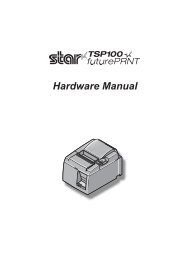
TSP100IIU Hardware Manual - POS systems
TSP100IIU Hardware Manual - POS systems
TSP100IIU Hardware Manual - POS systems
You also want an ePaper? Increase the reach of your titles
YUMPU automatically turns print PDFs into web optimized ePapers that Google loves.
Federal Communications CommissionRadio Frequency InterferenceStatementThis device complies with Part 15 of the FCC Rules. Operation is subject to the following two conditions: (1) This devicemay not cause harmful interference, and (2) this device must accept any interference received, including interference thatmay cause undesired operation.NOTE: This equipment has been tested and found to comply with the limits for a Class A digital device, pursuant to Part15 of the FCC Rules. These limits are designed to provide reasonable protection against harmful interference when theequipment is operated in a commercial environment. This equipment generates, uses and can radiate radio frequencyenergy and, if not installed and used in accordance with the instruction manual, may cause harmful interference to radiocommunications. Operation of this equipment in a residential area is likely to cause harmful interference in which casethe user will be required to correct the interference at his own expense.This statement will be applied only for the printers marketed in U.S.A.FCC WARNINGChanges or modifications not expressly approved by the party responsible for compliance could void the user’sauthority to operate the equipment.For compliance with the Federal Noise Interference Standard, this equipment requires a shielded cable.For RF interference suppression, if a ferrite core is provided with this device, affix it to the interface cableStatement ofThe Canadian Department of CommunicationsRadio Interference RegulationstThis Class A digital apparatus complies with Canadian ICES-003.Cet appareil numérique de la classe A est conforme à la norme NMB-003 du Canada.The above statement applies only to printers marketed in Canada.Trademark acknowledgmentsTSP100II: Star Micronics Co., Ltd.Notice• All rights reserved. Reproduction of any part of this manual in any form whatsoever, without STAR’s expresspermission is forbidden.• The contents of this manual are subject to change without notice.• All efforts have been made to ensure the accuracy of the contents of this manual at the time of going to press.However, should any errors be detected, STAR would greatly appreciate being informed of them.• The above notwithstanding, STAR can assume no responsibility for any errors in this manual.Copyright © 2010-2011 Star Micronics Co., Ltd..
TABLE OF CONTENTS1. Unpacking and Installation............................................................................................................................ 11-1. Unpacking.............................................................................................................................................................. 11-2. Choosing a place for the printer..................................................................................................................... 21-3. Nomenclature........................................................................................................................................................ 32. Product Features.............................................................................................................................................. 42-1. Product Features.................................................................................................................................................. 42-2. Operation Modes................................................................................................................................................. 43. Setup.................................................................................................................................................................. 53-1. Connecting the Power Cord............................................................................................................................. 53-2. Connecting the USB Cable to the Printer.................................................................................................... 63-3. Connecting to a Peripheral Unit..................................................................................................................... 73-4. Turning Power On and Power Off................................................................................................................... 83-5. Loading the Paper Roll.....................................................................................................................................104. Attaching the Accessories............................................................................................................................ 144-1. Attaching the Upper Guide............................................................................................................................144-2. Attaching the Holder Plate.............................................................................................................................154-3. Attaching the Rubber Feet.............................................................................................................................175. Thermal Roll Paper Specification................................................................................................................ 185-1. Roll paper specification....................................................................................................................................185-2. Recommended paper.......................................................................................................................................186. Control Panel and Other Functions............................................................................................................ 196-1. Control Panel.......................................................................................................................................................196-2. Lamp Indicator....................................................................................................................................................196-3. Self-Printing..........................................................................................................................................................217. Preventing and Clearing Paper Jams......................................................................................................... 227-1. Preventing Paper Jams.....................................................................................................................................227-2. Removing Paper Jam........................................................................................................................................227-3. Releasing a Locked Cutter ..............................................................................................................................248. Periodical Cleaning........................................................................................................................................ 268-1. Cleaning the Thermal Head............................................................................................................................268-2. Cleaning the Rubber Roller............................................................................................................................268-3. Cleaning the Paper Holder and the Surrounding Area........................................................................269. Peripheral Unit Drive Circuit........................................................................................................................ 2710. Specifications............................................................................................................................................... 2910-1. General Specifications......................................................................................................................................2910-2. Auto Cutter Specifications..............................................................................................................................3010-3. Interface.................................................................................................................................................................3010-4. Electrical Characteristics..................................................................................................................................3010-5. Environmental Requirements........................................................................................................................3110-6. Reliability...............................................................................................................................................................32Please access the following URLhttp://www.star-m.jp/eng/dl/dl02.htmfor the latest revision of the manual.
1-1. Unpacking1. Unpacking and InstallationAfter unpacking the unit, check that all the necessary accessories are included in the package.USB cablePaper roll holderPower cordScrewsRubber feetUpper guideHolder plateCD-ROMScrewsInstallation sheetPrinterRoll paperFig. 1-1 UnpackingIf anything is missing, contact the dealer where you bought the printer and ask them to supplythe missing part. Note that it is a good idea to keep the original box and all the packing materialsjust in case you need to pack the printer up again and send it somewhere at a later date.– 1 –
1-2. Choosing a place for the printerBefore actually unpacking the printer, you should take a few minutes to think aboutwhere you plan to use it. Remember the following points when doing this. Choose a firm, level surface where the printer will not be exposed to vibration. The power outlet you plan to connect to for power should be nearby and unobstructed. Make sure that the printer is close enough to your host computer for you to connectthe two. Make sure that the printer is not exposed to direct sunlight. Make sure that the printer is well away from heaters and other sources of extremeheat. Make sure that the surrounding area is clean, dry, and free of dust. Make sure that the printer is connected to a reliable power outlet. It should not be onthe same electric circuit as copiers, refrigerators, or other appliances that cause powerspikes. Make sure that the room where you are using the printer is not too humid. When disposing of the printer, obey local regulations. This device employs a DC motor and switches that have an electrical contact point.Avoid using the device in environments where silicon gas can become volatile.WARNING Shut down your equipment immediately if it produces smoke, a strange odor, or unusualnoise. Immediately unplug the equipment and contact your dealer for advice. Never attempt to repair this product yourself. Improper repair work can be dangerous. Never disassemble or modify this product. Tampering with this product may resultin injury, fire, or electric shock.– 2 –
1-3. NomenclatureCover open leverPush this lever in thedirection of the arrow toopen the printer cover.Printer coverOpen this cover to load orreplace paper.Control panelFeatures LED indicators to indicateprinter status and switches to operatethe printer.USB connectorFor connection to ahost computer using aUSB cable.Peripheral drive connectorConnects to peripheralunits such as cash drawers,etc.Do not connect this to atelephone.Power connectorFor connection of thepower cord.– 3 –
2-1. Product Features2. Product Features• This printer is not equipped with a power switch. The printer turns on when the computer,which the printer is connected to, is turned on.• After the paper is discharged, the roll paper is rewound to reduce the margin on the leadingedge of the paper, which reduces the amount of paper used.• The amount of paper used is reduced using small printing.• When the computer enters stand-by or hibernates, the printer automatically enters the printready mode or system off mode to reduce power consumption.• When the printer is not printing, the printer automatically enters the print ready mode toreduce power consumption while it is waiting for the next print job.(However, depending on the computer configuration and connection environment, theabove function may not operate.)2-2. Operation Modes• System Off ModeWhen the computer is turned off, the printer turns off.In addition, the printer enters the system off mode when the computer enters stand by orhibernates. (However, the printer continues to receive a very small amount of electricityfrom the power source in this case.)• Print Ready ModeWhen the printer is not printing, the printer automatically enters the print ready mode toreduce power consumption.• PrintingThe printer is printing (including when the roll paper is being fed)– 4 –
3-1. Connecting the Power Cord3. Setup(1) Check the label on the back or bottom of the printer to make sure its voltage matches thatof the AC outlet. Also make sure the plug on the power cord matches the AC outlet.(2) If the power cord is not attached to the printer, plug the appropriate end into the AC inleton the back of the printer.(3) Plug the power cord into a properly grounded AC outlet.CAUTIONIf the voltage shown on the label on the bottom of your printer does not match the voltage foryour area, contact your dealer immediately.We recommend that you unplug the printer from the power outlet whenever you do not plan touse it for long periods. Because of this, you should locate the printer so that the power outlet it isplugged into is nearby and easy to access.– 5 –
3-2. Connecting the USB Cable to the PrinterPass the cable through the cable support as shown. Then, connect the USB interface cable tothe printer.Precautions regarding USB connections1) Depending on the settings and configurations, the printer may not operate correctly with somecomputers even if they meet the conditions for the connection environment. In addition, operationis not guaranteed for connections through a USB hub or USB extension board, or for home-builtor modified computers.2) Connect the USB cable directly to the computer’s USB port. If the printer is connected through aUSB hub or other device, the printer may not operate correctly.3) This printer requires an electrical current of 100 mA/USB port or more for a given length of timeduring operations, such as startup. If the electrical current is less than 100 mA, the following devicesmay malfunction.• This printer• Devices connected to the computer’s other USB ports– 6 –
3-3. Connecting to a Peripheral UnitYou can connect a peripheral unit to the printer using a modular plug. The following describeshow to install the ferrite core and make the actual connection. See “Modular plug” onpage 28 for details about the type of modular plug that is required. Note that this printer doesnot come with a modular plug or wire, so it is up to you to obtain one that suits your needs.CAUTIONMake sure that the printer is turned off and unplugged from the AC outlet and that the computeris turned off before making connections.(1) Connect the peripheral drive cable to the connector on the rear panel of the printer.CAUTIONDo not connect a telephone line into the peripheral drive connector. Failure to observe this mayresult in damage to the printer.Also, for safety purposes, do not connect wiring to the external drive connector if there is a chanceit may carry peripheral voltage.– 7 –
3-4. Turning Power On and Power OffImportant:This printer is not equipped with a power switch.1) To turn on the printer, the following three conditions must be met.• The computer is turned on.• The printer's power cord is plugged into an AC outlet.• The printer is connected to a computer using the USB cable.2) If the printer is malfunctioning, unplug the power cord and disconnect the USB cable toturn off the printer.3-4-1. Turning Power On (Print Ready Mode)There are two ways to turn on the power.1) Turning power on manuallyMake sure that the printer’s power cord is plugged into an AC outlet.Connect the USB cable to the USB port of a computer that is turned on. When the USB cableis connected, the printer turns on and the POWER lamp on the control panel lights up.2) Turning power on automaticallyMake sure that the printer’s power cord is plugged into an AC outlet.Make sure that the USB cable is connected to the USB port of a computer that is turned off.When the computer is turned on, the printer turns on and the POWER lamp on the controlpanel lights up.3-4-2. Turning Power Off (System Off Mode)There are two ways to turn off the power.1) Turning power off manuallyUnplug the power cord and disconnect the USB cable.2) Turning power off automaticallyTurn off the computer. The printer also turns off whenthe computer enters stand-by or hibernates. However,the printer continues to receive a very small amount ofelectricity from the power. To completely turn off theprinter, unplug the power cord and disconnect the USBcable.– 8 –
CAUTION• Depending on the computer that is connected to the printer, the printer may not enter the systemoff mode even if the computer is turned off. To completely turn off the printer, unplug the powercord and disconnect the USB cable.• Depending on the type of hub used, the printer may not enter the system off mode even if thecomputer is turned off. To completely turn off the printer, unplug the power cord and disconnectthe USB cable.Precautions regarding USB connections1) Depending on the settings and configurations, the printer may not operate correctly with somecomputers even if they meet the conditions for the connection environment. In addition, operationis not guaranteed for connections through a USB hub or USB extension board, or for home-builtor modified computers.2) Connect the USB cable directly to the computer’s USB port. If the printer is connected through aUSB hub or other device, the printer may not operate correctly.3) This printer requires an electrical current of 100 mA/USB port or more for a given length of timeduring operations, such as startup. If the electrical current is less than 100 mA, the following devicesmay malfunction.• This printer• Devices connected to the computer’s other USB ports– 9 –
3-5. Loading the Paper Roll3-5-1. Using 79.5 mm Width Paper RollBe sure to use roll paper that matches the printer’s specification.When using a paper roll with an 57.5 mm width, install the paper roll holder as described onthe following pagethe following page.1) Push the cover open lever, and open the printercover.Cover open lever2) While observing the direction of the roll, set thepaper roll into the hollow, and pull on the leadingedge of the paper toward you.CAUTIONDo not pull out the end of the paper diagonally,as it will cause the paper to become jammed orskewed.Roll paper3) Push down both sides of the printer cover toclose.Note: Make sure that the printer cover is securelyclosed.4) If the printer cover is closed after turning on thepower, the cutter operates automatically and thefront end of the paper is cut.– 10 –
3-5-2. Using 57.5 mm Width Paper RollWhen using a paper roll with 57.5 mm width, install the supplied paper guide on the printer.To change the effective print width (roll paper width), change the setting of the Print Width inthe Configuration. For details on the setting of the Print Width, refer to the software manuallocated in the “Documents” folders on the CD-ROM.1 Insert the paper roll holder into the unit, making sure not to touch the assist roller, andthen fit the holder into the slots as shown.Paper Roll Holder2 Secure the paper guide by pushing the area marked “A” down until it clicks into place.ANote: After using a paper roll with a width of 57.5 mm, do not change to a paper roll witha width of 79.5 mm. (This is because the printer head has deteriorated as a result of aportion of the head having been in direct contact with the platen.)– 11 –
Caution SymbolThese labels are located near the thermal print head.Because the thermal print head is hot immediately after printing, do nottouch it. Static electricity can damage the thermal print head. To protect thethermal print head from static electricity, do not touch it.This symbol is placed near the cutter.Never touch the cutter blade, as you could injure your fingers.This symbol is placed near the peripheral drive connector.Do not connect this to a telephone.This symbol label or stamp is placed near the screws securing the case orthe protective plate, which should not be opened by individuals other thanservice personnel. Individuals, other than service personnel, should notremove these screws. High voltage areas in the case can be dangerous.Thermal headWARNING1) Do not touch the cutter blade.• There is a cutter inside the paper outlet slot. Not only should you not put your hand inthe paper outlet slot while printing is in progress, never put your hand into the outlet evenwhen printing is not in progress.• The printer cover can be opened when replacing the paper. However, since the cutter bladeis on the inside of the printer cover, be careful not to place your face or hands too close tothe cutter blade.2) During and immediately after printing, the area around the thermal head is very hot. Donot touch it, as you could be burned.3) Unplug the equipment immediately if it produces smoke, a strange odor, or unusual noiseand contact your dealer for advice.4) Never attempt to repair this product yourself. Improper repair work can be dangerous.5) Never disassemble or modify this product. Tampering with this product may result in injury,fire, or electric shock.– 12 –
CAUTION1) Do not operate the cover open lever while pressing on the printer cover with your hand.2) Do not push the cover open lever and open the printer cover when printing is in progress orwhen the auto cutter is operating.3) Do not push out paper while the printer cover is closed.4) The heating element and the driver IC of the thermal head are easily damaged. Do not touchthem with metal objects, sandpaper, etc.5) Printing quality may suffer if the thermal head heating element becomes soiled by beingtouched with your hands. Do not touch the thermal head heating element.6) There is a risk of damage to the driver IC of the thermal head from static electricity. Neverdirectly touch the IC.7) The printing quality and working life of the thermal head cannot be guaranteed if any paperother than that recommended is used. In particular, paper containing [Na+, K+, C1-] maydrastically reduce the working life of the thermal head. Please exercise caution.8) Do not operate the printer if there is moisture on the front surface of the head from condensation,etc.9) A printed piece of thermal paper may become electrically charged. If the printer is placedvertically or mounted on a wall, the cut piece of paper may stick to the printer, instead offalling. Beware that this could cause a problem if you use a stacker that stores the pieces ofpaper that fall freely.10) Do not change the paper width during use. The thermal printing head, rubber roller, andcutter wear differently according to the paper width. This can cause the printing or cuttermovement to malfunction.11) Do not transport the printer with its cover open and holding it by the cover.12) Do not forcibly pull on the interface cable, power cord, or cash drawer cable that is connected.To detach a connector, make sure to grasp it at the connector portion, without applyingexcessive stress on the connector at the printer13) If your printer gets hang-up, you must reset it by plugging out/in the USB cable. However,the intervals of per plugging out/in must be 5 seconds or more. Shorter interval may causemalfunction.14) Do not turn off the computer or put the cpmputer in stand-by mode during printing.15) Do not unplug the power cord or disconnect the USB cable during it is working.Notes on Using the Auto Cutter1) If the cutter is not in its home position after an error, first eliminate the cause of the error;then, turn the power back ON.2) A margin of 5 mm or more is recommended from the end of the printed area to the cuttingposition.3) Do not attempt to remove the paper during a cut, as this can cause a paper jam– 13 –
4. Attaching the AccessoriesThe following accessories are necessary when mounting the printer to a wall.• Upper guide and two flanged screws• Holder plate and two flangeless screwsThe following accessories are necessary when positioning the printer vertically.• Upper guide and two flanged screws• Four rubber feet4-1. Attaching the Upper Guide1) Push the cover open lever, and open the printer cover.2) Fit the upper guide onto the shaft until the hooks on the guide click into place.3) Tighten the two screws (M3x6 flanged screws) that were supplied to secure the upper guidein place.Upper guideShaftHooksFlanged screws– 14 –
4-2. Attaching the Holder Plate• The holder plate is attached to the printer using the included screws and is hooked ontoscrews that are installed into the wall.• The screws on the wall are not included.Use commercially available screws (4 mm diameter) that are suitable for the wall material(wood, steel beam, concrete, etc.).• The printer’s weight is approximately 2.4 kg when the largest diameter roll paper is loaded.Use screws on the wall that have both shear strength and pulling-out strength to withstanda force of at least 12 kgf (118 N).Precautions regarding installationCAUTIONThis caution indicates information that, if ignored, could lead to personal injury or propertydamage.• Be sure to have qualified personnel install the specified screws and printer to the wall.Star is not responsible for any accidents or injuries that occur as a result of improper installation,misuse, or modifications.Especially when installing the printer at a high location, make sure that the printer is securelyinstalled to the wall.If the printer is not installed securely and falls, personal injury or damage to the printer mayresult.• Make sure that the mounting surface and installation screws are strong enough to install theprinter.Securely install the printer so that the weight of the printer and any connected cables will notcause the printer to fall.Otherwise, personal injury or damage to the printer may result.• Do not install the printer in an unstable location or a location that is exposed to vibration andshocks.If the printer falls, personal injury or damage to the printer may result.– 15 –
(1) Attach the holding plate to the printer.Then tighten the two screws that weresupplied to secure it in place.Flangeless screwsø7 or more2 to 3 mmø4(2) Position the printer over the screws, etc.,on the wall and then slide it downward toset it in place.After setting the printer in place, checkthe screws on the wall again to make surethat they are able to support the printer’sweight.CAUTION• The printer’s weight is approximately2.4 kg when the largest diameter roll paperis loaded.• Use screws on the wall that have bothshear strength and pulling-out strengthto withstand a force of at least 12 kgf(118 N).(3) Push the cover open lever, and open theprinter cover.(4) Insert the roll paper as shown.– 16 –
4-3. Attaching the Rubber Feet(1) Attach the four rubber feet in the positionsshown in the figure.Ensure that any soiling has been completelywiped off before attaching therubber feet.(2) Push the cover open lever, and open theprinter cover.(3) Insert the roll paper as shown.– 17 –
5. Thermal Roll Paper SpecificationWhen consumable parts have run out, use those specified below.5-1. Roll paper specificationThermal paperThickness: 57~85 µmNote: When using thin paper with a thickness of less than 65 μm, only the F5041(Mitsubishi HiTec Paper Flensburg GmbH),TF50KS-E2D (Nippon Paper Industries)and P300/P310 (KSP) paper types are recommended.Width: 79.5±0.5 mm (57.5±0.5 mm when the paper roller holder is used)Outer roll diameter: ø83 mm or less+ 0.5+ 0.5Take up paper roll width: 80 -1 mm or (58 -1 mm when the paper roller holder is used)Core outer/inner diameterCore outer Core innerø18±1 mm ø12±1 mmPrinted surface: Outer edge of rollTail end handling: Do not use paste or glue to secure the roll paper or its core.Do not fold the tail end of the paper.5-2. Recommended paperNote: 1) The print density may vary depending on the type of roll paper and operatingenvironment.2) A reader or scanner may not be able to scan a printed bar code or charactersdepending on the print density. Make sure that your reader or scanner is able toscan correctly beforehand.Manufacturer Product name Quality characteristics/Use Paper thickness (µm)Mitsubishi PaperMills LimitedP220AG normal type paper 65 (thickness)HP220A high image stability paper 65 (thickness)HP220AB-1 high image stability paper 75 (thickness)Mitsubishi HiTec PaperFlensburg GmbHF5041 normal type paper 60 (thickness)PD150R normal type paper 75 (thickness)Oji Paper Co., Ltd. PD160R high image stability paper 65/75 (thickness)PD450 normal type paper 65 (thickness)Nippon Paper IndustriesTF50KS-E2D normal type paper 59 (thickness)TF60KS-E normal type paper 75 (thickness)P320RB 2 color paper: Red & Black 65 (thickness)Kanzaki SpecialtyP320BB 2 color paper: Blue & Black 65 (thickness)Papers Inc. (KSP)P300/P310 normal type paper 57/58 (thickness)Note: The P300/P310 (KSP) paper types cannot be used when the printer is positioned vertically.Note:Access the following URL for the information of the recommended paper.http://www.star-m.jp/eng/dl/dl02.htm– 18 –
6. Control Panel and Other Functions6-1. Control Panel1 POWER lamp (Green LED)Lights when the power is ON.3 FEED button2 ERROR lamp (Red LED)1 POWER lamp (Green LED)Important:This printer is not equipped with a powerswitch. After plugging the power cord intoan AC outlet, the printer power will beturned on for the first time when the USBcable is connected to a computer that isturned on.2 ERROR lamp (Red LED)Indicates various errors in combinationwith POWER lamp.6-2. Lamp Indicator1) Printer StatusStatus POWER Lamp ERROR LampPrinting On OffPrint Ready On OffSystem Off Off OffErrors Refer to next page. Refer to next page.3 FEED buttonPress the FEED button to feed roll paper.Note: Depending on the USB port used, it may take a short time for the printer to enter thesystem off mode after the computer is turned off.– 19 –
2) Automatically recoverable errorsError Description POWER Lamp ERROR Lamp Recovery ConditionsCover open error On On Automatically recovered after the printercover is closed.Power cord disconnectionerrorFlashes at 0.5-secondintervals *1Flashes at 0.5-secondintervals *1Automatically recovered after the powercord is plugged into an AC outlet.Head high tempera-Flashes at 0.5-sec-OffAutomatically recovered after the printture detectionBoard high temperaturedetectionond intervalsFlashes at 2-secondintervalsOffhead has cooled.Automatically recovered after the printercover is closed.*1: The POWER and ERROR lamps blink alternately. If the VM and VCC voltage errors occurredsimultaneously, the power cord disconnection error will be displayed even thoughthe cable is connected to an outlet. In such cases, disconnect the power cord from the outlet,then reconnect it. Then connect the USB cable to the PC when it power.3) Non-recoverable errorsError Description POWER Lamp ERROR Lamp Recovery ConditionsHead thermistor error Flashes at 0.5-second intervalvalsFlashes at 0.5-second inter-Non-recoverableBoard thermistor error Flashes at 2-second intervals Flashes at 2-second intervals Non-recoverableVM voltage error Off Flashes at 1-second intervals Non-recoverableVCC voltage error Flashes at 1-second intervals Flashes at 1-second intervals Non-recoverableNonvolatile memory Flashes at 0.25-second intervalvalsFlashes at 0.25-second inter-Non-recoverableerrorUSB error Flashes at 5-second intervals Flashes at 5-second intervals Non-recoverableCPU error Off Off Non-recoverableRAM error Off On Non-recoverableNote: 1) If a non-recoverable error occurs, turn the power OFF immediately.2) If a non-recoverable error occurs, please consult the dealer for repairs.4) Paper cut errorError Description POWER Lamp ERROR Lamp Recovery ConditionsPaper cut error Off Flashes at0.125-secondintervalsFor firmware version 1.1 or later:Open the printer cover.Remove the cause(jammed paper) of the error, and close theprinter cover.Then, the printer will be recovered.For firmware version 1.0 or if the printer covercannot be opened because of the cutter lock:Follow the steps described in section 7-3.Note: If the cutter does not return to its home position or does not perform the initial movement,it will result in a non-recoverable error.5) Paper out errorError Description POWER Lamp ERROR Lamp Recovery ConditionsPaper out error On Flashes at 0.5-secondintervalsAutomatically recovered by loading anew paper roll, then closing the printercover.– 20 –
6-3. Self-PrintingTest Printing1) Make sure that the computer is turned on.2) Make sure that the printer’s power cord is plugged into an AC outlet.3) While holding the FEED button down, connect the USB cable to the computer.Test printing starts. The version number and printer settings are printed.After the printer starts printing, release your hand from the FEED button.After self-printing is completed, the printer will start in the normal mode.– 21 –
7. Preventing and Clearing Paper Jams7-1. Preventing Paper JamsThe paper should not be touched during ejection and before it is cut.Pressing or pulling the paper during ejection may cause a paper jam, paper cutting failure orline feed failure.7-2. Removing Paper JamIf a paper jam occurs, clear it as described below.(1) Unplug the power cord and disconnect the USB cable.(2) Push the lever toward you to open the printer cover.(3) Remove the jammed paper.Note: To prevent parts such as the thermal head or the rubber roller from damage ordeformation, do not forcibly pull on the paper with the printer cover closed.(4) Position the paper roll straight and close the printer cover gently.Note 1: Make sure that the paper is positioned straight. If the printer cover is closed withthe paper skewed, a paper jam may result.Note 2: Lock the printer cover by pressing down on the sides. Do not try to close it bypressing down on the centre. The cover may not lock properly.(5) Plug the power cord into the AC outlet and connect the USB cable to the computer that isturned on. Then make sure that the ERROR LED is not lit.Note: While the ERROR LED is lit, the printer will not accept any commands such asthe print command, so make sure that the printer cover is locked properly.– 22 –
Caution SymbolThese labels are located near the thermal print head.Because the thermal print head is hot immediately after printing, do nottouch it. Static electricity can damage the thermal print head. To protect thethermal print head from static electricity, do not touch it.This symbol is placed near the cutter.Never touch the cutter blade, as you could injure your fingers.This symbol is placed near the peripheral drive connector.Do not connect this to a telephone.This symbol label or stamp is placed near the screws securing the case orthe protective plate, which should not be opened by individuals other thanservice personnel. Individuals, other than service personnel, should notremove these screws. High voltage areas in the case can be dangerous.Thermal head– 23 –
7-3. Releasing a Locked CutterIf the auto cutter locks up, disconnect the USB cable, and unplug the power cord to turn theprinter off. Then reconnect the USB cable, and plug in the power cord to turn the printer on.If restarting the printer does not release the locked cutter, follow the steps below.WARNINGSince working on the cutter may be dangerous, be sure to turn off the printer first.(1) Unplug the power cord and disconnect the USB cable.(2) Remove the front cover to reveal the auto cutter.Front coverAuto cutter(3) Remove any jammed paper.CAUTION: Be careful not to damage the printer while removing any jammed paper.Since the thermal print head is particularly sensitive, be sure not to touch it.– 24 –
(4) Insert a Philips screwdriver into the manual operation hole on the side of the cutter, andturn it in the direction of the arrow shown on the right until the rear cover is opened.CAUTION: If the printer cover does not open easily, do not force the printer cover open.Consult the dealer for repairs.(5) Open the printer cover, remove any jammed paper, and then reinstall the paper roll.(6) Install the front cover.– 25 –
8. Periodical CleaningPrinted characters may become partially unclear due to accumulated paper dust and dirt. Toprevent such a problem, paper dust collected in the paper holder and paper transport sectionand on the surface of the thermal head must be removed periodically.Such cleaning is recommended to be carried out once six month or one million lines.8-1. Cleaning the Thermal HeadTo remove the dark paper dust that has accumulated on the thermal head surface, wipe itclean with cotton swab (or soft cloth) dipped in alcohol (ethanol, methanol, or isopropyl alcohol).Note 1: The thermal head is easily damaged, so clean it with a soft cloth, taking care notto scratch it.Note 2: Do not attempt to clean the thermal head immediately after printing, when thethermal head is hot.Note 3: Beware of the risk of damaging the thermal head as a result of static electricitythat may be created during cleaning.Note 4: Turn the power ON only after the alcohol has dried completely.8-2. Cleaning the Rubber RollerUse a dry, soft cloth to wipe off the dust that may have accumulated on the rubber roller.Rotate the platen to clean the entire surface.8-3. Cleaning the Paper Holder and the Surrounding AreaClean the paper holder of debris, dust, paper particles, glue, etc. that may have accumulated.Rubber rollerThermal head– 26 –
9. Peripheral Unit Drive CircuitPeripheral unit drive circuit connector only connects to peripheral units such as cash drawers, etc.Do not connect it to a telephone.Use cables which meet the following specifications.Peripheral Drive ConnectorPin No.SignalI/OFunctionnamedirection1 FG Frame ground —2 DRD1 Drive signal 1 OUT3 +24 V Drive power OUT4 +24 V Drive power OUT5 DRD2 Drive signal 2 OUT6 DRSNS Sense signal INDrive circuitThe recommended drive unit is shown below.Modular plugModular jack plug1 6ShieldWire leadManufacturer ModelMOLEX 90075-0007AMP 641337FCIB-66-4Note: Connect a shielded wire to pin 1(frame ground).+24V6P ModularShielded cable21Q4VCCVIN VOUT782410k3SS14SX34M-GND2SD1866FUSE 2A2SD1866GS1DGS1D345L1L2Peripheral unit 1Peripheral unit 2Compulsion switch6 16-pin modularjack connectorVCC4.7kM-GND61C387533k10k0.022uFGFrameReference2SD 1866 Circuit ConfigurationCR3= 3.5KΩR4= 300ΩDrive Output:24 V, Max. 1.0 ABR3R4E– 27 –
Notes: 1. Peripheral units 1 and 2 cannot be driven simultaneously. To drive themcontinuously, set the duty cycle ratio to 20% or less (excluding an externallyconnected buzzer).2. The following external buzzer unit is available as an option.External buzzer model: BU01-24-A3. Never use the external buzzer command if you connect a device (such as acash drawer) other than an external buzzer. It could damage the connecteddevice and the printer circuit. Refer to the separate Programmer's <strong>Manual</strong> fordetails on commands.4. The status of the compulsion switch can be known from the status command.Refer to the separate Programmer's <strong>Manual</strong> for details.5. Minimum resistance for coils L1 and L2 is 24.6. Absolute maximum ratings for diodes D1 and D2 (Ta = 25°C) are:Average Rectified Current Io = 1A7. Absolute maximum rating for transistors TR1 and TR2 (Ta = 25°C) are:Collector current IC = 2.0 A8. When the printer enters the print ready mode, Q4 in the drive circuit is off.Therefore, the voltage supplied to peripheral devices is the VCC voltage(approximately 3.3 V).– 28 –
10-1. General Specifications10. Specifications(1) Printing method Direct line thermal printing(2) Print speed Max. 1200 dots/sec. (150 mm/sec.)(3) Dot density Standard 8 dots/mm (203 dpi)(4) Printing width Max. 72 mm(5) Roll paper Refer to chapter 5 for details on the recommended roll paper.Paper width:79.5±0.5 mm57.5±0.5 mm when the paper roll holder is used)Roll diameter: ø83 mm or less(6) Overall dimension 142 (W) × 204 (D) × 132 (H) mm(7) Weight 1.72 kg (without roll paper)(8) Noise Approx. 50 dBNote: The noise measurements listed above were obtained accordingto conditions established by this company. Thenoise measurements may vary depending on the typeof paper used, type of printing and operating environment.142 mm132 mm204 mm– 29 –
10-2. Auto Cutter Specifications(1) Cutting frequency Max. 20 cuts per minute(2) Thickness of paper 65~85 µm10-3. Interface(1) Specifications USB 2.0 full speedPrinter class and vendor class compatible(2) Connector Type BType B connector:DUSB-BRA42-T11(D2)-FA (manufacturer: DDK) or equivalentPin No. Signal name Function1 VBUS USB Power pin (+5V DC)2 D - Serial Date -3 D + Serial Date +4 GND Signal ground2 13 410-4. Electrical Characteristics(1) Input Voltage AC 100 - 240 V±10%, 50/60 Hz(2) Current ConsumptionSystem off mode:Approx. 0.05 W on averagePrint ready mode:Approx. 0.76 W on averageASCII character continuous printing: Approx. 34 W– 30 –
10-5. Environmental Requirements(1) OperatingTemperature 5°C to 45°CHumidity10% to 90% RH (without condensation)(%RH)908034°C 90% RH60Relative humidity4040°C 65% RH45°C 50% RHOperating environment20100 10 20 30 40 50Temperature (°C)Operating temperature and humidity range(2) Transport/storage (except for paper)Temperature -20°C to 60°CHumidity10% to 90% RH (without condensation)– 31 –
10-6. Reliability1) Life Mechanical: 20 million linesThe lifes of the Head and Cutter may vary depending on the paper specifications.They are shown in the table below:Average printing ratio: 12.5%Average head resistance fluctuation: Max. ±15%ManufacturerMitsubishi PaperMills LimitedProduct nameNumber ofPulsesHead lifeDistancePaper width:79.5mm(cuttings)Cutter lifePaper width:57.5mm(cuttings)P220AG 100 million 100 Km 1 million 0.6 millionHP220A 100 million 100 Km 1 million 0.6 millionHP220AB-1 100 million 100 Km 1 million 0.6 millionP220AGB 100 million 100 Km 1 million 0.6 millionMitsubishi HiTec PaperF5041 100 million 100 Km 1 million 0.6 millionFlensburg GmbHOji Paper Co., Ltd. PD150R 100 million 100 Km 1 million 0.6 millionPD160R 100 million 100 Km 1 million 0.6 millionPD450 100 million 100 Km 1 million 0.6 millionNippon Paper Industries TF50KS-E2D 100 million 100 Km 1 million 0.6 millionTF60KS-E 100 million 100 Km 1 million 0.6 millionKanzaki SpecialtyPapers Inc. (KSP)P320RB 50 million 50 Km 1 million 0.6 millionP320BB 50 million 50 Km 1 million 0.6 millionP300/P310 100 million 100 Km 0.5 million 0.3 million2) MCBF: 60 million linesThe Mean Cycle Between Failure (MCBF) is defined to be the overall failure cycle, whichincludes random or wear failures that occur until the printer reaches its mechanical life of20 million lines.* As the mechanical remains at 20 million lines, the MCBF of 60 million lines does not indicateits useful life.* All the reliability values indicated above are based on the use of the recommended thermalpaper. No reliability can be guaranteed for the use of non-recommended thermal paper.– 32 –
SPECIAL PRODUCTS DIVISIONSTAR MICRONICS CO., LTD.536 Nanatsushinya, Shimizu-ku, Shizuoka,424-0066 JapanTel: (int+81)-54-347-0112, Fax: (int+81)-54-347-0409Please access the following URLhttp://www.star-m.jp/eng/dl/dl02.htmfor the latest revision of the manual.OVERSEAS SUBSIDIARY COMPANIESSTAR MICRONICS AMERICA, INC.1150 King Georges Post Road, Edison, NJ 08837-3729 U.S.A.Tel: (int+1)-732-623-5555, Fax: (int+1)-732-623-5590STAR MICRONICS EUROPE LTD.Star House, Peregrine Business Park, Gomm Road,High Wycombe, Bucks, HP13 7DL, U.K.Tel: (int+44)-1494-471111, Fax: (int+44)-1494-473333






![MC9190-G Quick Start Guide [Spanish] (P/N 72-139206-01ES Rev. A)](https://img.yumpu.com/50178248/1/178x260/mc9190-g-quick-start-guide-spanish-p-n-72-139206-01es-rev-a.jpg?quality=85)
