VCP25.1 Project Planning Manual - Bosch Rexroth
VCP25.1 Project Planning Manual - Bosch Rexroth
VCP25.1 Project Planning Manual - Bosch Rexroth

You also want an ePaper? Increase the reach of your titles
YUMPU automatically turns print PDFs into web optimized ePapers that Google loves.
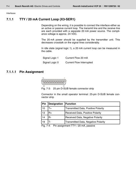
7-4 <strong>Bosch</strong> <strong>Rexroth</strong> AG | Electric Drives and Controls <strong>Rexroth</strong> IndraControl VCP 25 | R911299720 / 02Interfaces7.1.1 TTY / 20 mA Current Loop (X3-SER1)Depending on the wiring, it is possible to connect the interface either asan active or passive current loop. The transmit line and the receive lineare each provided with a separate 20 mA power source. The compliancevoltage is approx. 24 VDC.The 20 mA power should be supplied by the transmitter unit. Thisdecreases crosstalk on the signal lines considerably.In idle state (signal logic 1), a 20 mA current loop can be measured inthe cable.Signal Logic 1Signal Logic 0Current Flow 20 mACurrent Flow Interrupted7.1.1.1 Pin AssignmentFig. 7-3:25 pin D-SUB female connector stripConnector in the small operator terminal: 25-pin D-SUB female connectorstripPin Designation Function10 T+ Transmitted Data, Positive Polarity13 R+ Received Data, Positive Polarity14 R- Received Data, Negative Polarity19 T- Transmitted Data, Negative PolarityFig. 7-4: Pin assignment TTY / 20 mA, passive