VCP25.1 Project Planning Manual - Bosch Rexroth
VCP25.1 Project Planning Manual - Bosch Rexroth
VCP25.1 Project Planning Manual - Bosch Rexroth
Create successful ePaper yourself
Turn your PDF publications into a flip-book with our unique Google optimized e-Paper software.
IndustrialHydraulicsElectric Drivesand ControlsLinear Motion andAssembly TechnologiesPneumaticsServiceAutomationMobileHydraulics<strong>Rexroth</strong> IndraControl VCP 25R911299720Edition 02<strong>Project</strong> <strong>Planning</strong> <strong>Manual</strong>
IV <strong>Bosch</strong> <strong>Rexroth</strong> AG | Electric Drives and Controls <strong>Rexroth</strong> IndraControl VCP 25 | R911299720 / 02Contents5.1.3 Side View, Mounting Depth .......................................... 5–45.1.3.1 Standard Device ........................................................ 5–45.1.3.2 Field Bus Device........................................................ 5–56 Display and Operating Components......... 6–16.1 Display............................................................................. 6–16.1.1 Setting the Contrast / Brightness.................................. 6–16.1.2 Default Contrast / Default Brightness Setting ............... 6–26.1.3 Character Attributes...................................................... 6–26.1.4 Fonts............................................................................. 6–26.2 Touch Screen .................................................................. 6–36.3 Reset Key........................................................................ 6–36.4 User Mode Switch ........................................................... 6–37 Interfaces..................................................... 7–17.1 Standard Interfaces ......................................................... 7–27.1.1 TTY / 20 mA Current Loop (X3-SER1) ......................... 7–47.1.1.1 Pin Assignment.......................................................... 7–47.1.1.2 Termination................................................................ 7–57.1.2 RS485 (X3-SER1) ........................................................ 7–67.1.2.1 Pin Assignment.......................................................... 7–67.1.2.2 Termination................................................................ 7–67.1.3 RS232c (X3-SER1) ...................................................... 7–87.1.3.1 Pin Assignment.......................................................... 7–87.1.3.2 Termination................................................................ 7–87.1.4 RS232c (X3-SER2) ...................................................... 7–97.1.4.1 Pin Assignment.......................................................... 7–97.2 Field Bus Interfaces....................................................... 7–107.2.1 DeviceNet ................................................................... 7–107.2.1.1 Pin Assignment........................................................ 7–127.2.1.2 Cable ....................................................................... 7–127.2.1.3 Termination.............................................................. 7–137.2.1.4 Diagnostics .............................................................. 7–137.2.2 INTERBUS ................................................................. 7–147.2.2.1 Pin Assignment........................................................ 7–167.2.2.2 Cable ....................................................................... 7–177.2.2.3 Diagnostics .............................................................. 7–177.2.3 PROFIBUS DP ........................................................... 7–187.2.3.1 Pin Assignment........................................................ 7–207.2.3.2 Cable ....................................................................... 7–207.2.3.3 Termination.............................................................. 7–217.2.3.4 Diagnostics .............................................................. 7–217.3 Memory Card (Option)................................................... 7–227.3.1 Inserting the Memory Card ......................................... 7–227.3.2 Ejecting the Memory Card .......................................... 7–237.4 Shielding D-SUB Connectors ........................................ 7–238 Maintenance and Installation..................... 8–18.1 General Information......................................................... 8–18.2 Exchange of Hardware Components .............................. 8–1
R911299720 / 02 | <strong>Rexroth</strong> IndraControl VCP 25 Electric Drives and Controls | <strong>Bosch</strong> <strong>Rexroth</strong> AG VContents8.3 Data Backup .................................................................... 8–18.4 Unpacking the Device...................................................... 8–18.5 Identification .................................................................... 8–28.6 Connecting ...................................................................... 8–38.6.1 Supply Voltage 24 V ..................................................... 8–38.7 Front Panel ...................................................................... 8–58.8 Fuse................................................................................. 8–58.9 Battery ............................................................................. 8–68.9.1 Changing the Battery .................................................... 8–68.9.2 Battery Disposal............................................................ 8–79 Ordering Information .................................. 9–19.1 Type Code ....................................................................... 9–19.2 Accessories ..................................................................... 9–210 List of Figures ........................................... 10–111 Index........................................................... 11–112 Service & Support ..................................... 12–112.1 Helpdesk........................................................................ 12–112.2 Service-Hotline .............................................................. 12–112.3 Internet .......................................................................... 12–112.4 Vor der Kontaktaufnahme... - Before contacting us....... 12–212.5 Kundenbetreuungsstellen - Sales & Service Facilities .. 12–212.5.1 Deutschland - Germany.............................................. 12–212.5.2 Europa (West) - Europe (West) .................................. 12–312.5.3 Europa (Ost) - Europe (East)...................................... 12–412.5.4 Afrika, Asien, Australien (inkl. Pazifischer Raum) -Africa, Asia, Australia (incl. Pacific Rim)..................... 12–512.5.5 Nordamerika - North America ..................................... 12–612.5.6 Südamerika - South America...................................... 12–6
VI <strong>Bosch</strong> <strong>Rexroth</strong> AG | Electric Drives and Controls <strong>Rexroth</strong> IndraControl VCP 25 | R911299720 / 02Contents
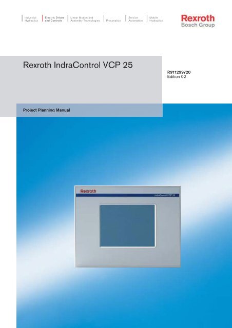
R911299720 / 02 | <strong>Rexroth</strong> IndraControl VCP 25 Electric Drives and Controls | <strong>Bosch</strong> <strong>Rexroth</strong> AG 1-1System Presentation1 System Presentation1.1 Brief Description of the VCP 25The small operator terminal VCP 25 is a machine operator terminalwhich can initiate functions in the machine as defined in the application.Special features of the VCP 25 are its compact design and the sealrunning around the rear. Thus, it is suitable for various applications.Furthermore, every mounting position is possible.Depending on the variant, the small operator terminal is equippedeither with three serial standard interfaces or with a field bus interface.The front panel with touch screen allows to operate the application softwarevia the touch-sensitive surface of the display without keyboard.Fig. 1-1:VCP 25 with touch screen
1-2 <strong>Bosch</strong> <strong>Rexroth</strong> AG | Electric Drives and Controls <strong>Rexroth</strong> IndraControl VCP 25 | R911299720 / 02System Presentation1.2 Operating systemA special operating system is installed on the small operator terminal. Ifnecessary, this operating system can be reloaded into the device (firmwaredownload). This can be done with the associated programmingsoftware "VI Composer".1.3 CommissioningMount the device properly (for more information, see chapter Dimensions).Then connect the device to the voltage supply and to the controlunit or the field bus system, if required.
R911299720 / 02 | <strong>Rexroth</strong> IndraControl VCP 25 Electric Drives and Controls | <strong>Bosch</strong> <strong>Rexroth</strong> AG 2-1Important Directions for Use2 Important Directions for Use2.1 Appropriate Use2.1.1 Introduction<strong>Rexroth</strong> products represent state-of-the-art developments and manufacturing.They are tested prior to delivery to ensure operating safetyand reliability.The products may only be used in the manner that is defined as appropriate.If they are used in an inappropriate manner, then situations candevelop that may lead to property damage or injury to personnel.<strong>Bosch</strong> <strong>Rexroth</strong>, as manufacturer, is not liable for any damages resultingfrom inappropriate use. In such cases, the guarantee and the right topayment of damages resulting from inappropriate use are forfeited. Theuser alone carries all responsibility of the risks.Before using <strong>Rexroth</strong> products, make sure that all the pre-requisites forappropriate use of the products are satisfied:• Personnel that in any way, shape or form uses our products must firstread and understand the relevant safety instructions and be familiarwith appropriate use.• If the product takes the form of hardware, then they must remain intheir original state, in other words, no structural changes are permitted.It is not permitted to decompile software products or alter sourcecodes.• Do not mount damaged or faulty products or use them in operation.• Make sure that the products have been installed in the manner describedin the relevant documentation.
2-2 <strong>Bosch</strong> <strong>Rexroth</strong> AG | Electric Drives and Controls <strong>Rexroth</strong> IndraControl VCP 25 | R911299720 / 02Important Directions for Use2.1.2 Areas of Use and ApplicationThe small operator terminal VCP 25 made by <strong>Bosch</strong> <strong>Rexroth</strong> allows tooperate and control machines and installations and serves to visualizethe information on the machine/installation to be operated required bythe user.The VCP 25 may only be used with the accessories and parts specifiedin this document. If a component has not been specifically named, thenit may not be either mounted or connected. The same applies to cablesand lines.Operation is only permitted in the specified configurations and combinationsof components using the software and firmware as specified in therelevant function descriptions.The small operator terminals VCP 25 have been developed for use insingle or multiple-axis control tasks.Typical applications of the VCP 25 are:• Handling and assembly systems,• Packaging machines,• Printing and paper processing machines and• Machine tools.The VCP 25 may only be operated under the assembly, installation andambient conditions as described here (temperature, system of protection,humidity, EMC requirements, etc.) and in the position specified.2.2 Inappropriate UseUsing the small operator terminal outside of the above-referencedareas of application or under operating conditions other than describedin the document and the technical data specified is defined as “inappropriateuse".The small operator terminal may not be used, if• they are subject to operating conditions that do not meet the abovespecified ambient conditions. This includes, for example, operationunder water, in the case of extreme temperature fluctuations or extremelyhigh maximum temperatures or if• <strong>Bosch</strong> <strong>Rexroth</strong> has not specifically released them for that intendedpurpose. Please note the specifications outlined in the general SafetyGuidelines!
R911299720 / 02 | <strong>Rexroth</strong> IndraControl VCP 25 Electric Drives and Controls | <strong>Bosch</strong> <strong>Rexroth</strong> AG 3-1Safety Instructions for Electric Drives and Controls3 Safety Instructions for Electric Drives and Controls3.1 IntroductionRead these instructions before the initial startup of the equipment inorder to eliminate the risk of bodily harm or material damage. Followthese safety instructions at all times.Do not attempt to install or start upthis equipment without first reading all documentation provided with theproduct. Read and understand these safety instructions and all userdocumentation of the equipment prior to working with the equipment atany time. If you do not have the user documentation for your equipment,contact your local <strong>Bosch</strong> <strong>Rexroth</strong> representative to send thisdocumentation immediately to the person or persons responsible forthe safe operation of this equipment. If the equipment is resold, rentedor transferred or passed on to others, then these safety instructionsmust be delivered with the equipment.WARNINGImproper use of this equipment, failure to follow the safety instructionsin this document or tampering with the product, includingdisabling of safety devices, may result in material damage, bodilyharm, electric shock or even death!3.2 ExplanationsThe safety instructions describe the following degrees of hazard seriousnessin compliance with ANSI Z535. The degree of hazard seriousnessinforms about the consequences resulting from non-compliancewith the safety instructions.WarningsymbolSignal word and degree of hazard seriousnessaccording to ANSIDANGERDeath or severe bodily harm will occur.WARNINGDeath or severe bodily harm may occur.CAUTIONBodily harm or material damage may occur.Fig. 3-1: Hazard classification (according to ANSI Z535)
3-2 <strong>Bosch</strong> <strong>Rexroth</strong> AG | Electric Drives and Controls <strong>Rexroth</strong> IndraControl VCP 25 | R911299720 / 02Safety Instructions for Electric Drives and Controls3.3 Hazards by Improper UseDANGERHigh voltage and high discharge current! Danger to life or severe bodilyharm by electric shock!DANGERDangerous movements! Danger to life, severe bodily harm or materialdamage by unintentional motor movements!WARNINGHigh electrical voltage due to wrong connections! Danger to life or bodilyharm by electric shock!WARNINGHealth hazard for persons with heart pacemakers, metal implants andhearing aids in proximity to electrical equipment!CAUTIONSurface of machine housing could be extremely hot! Danger of injury!Danger of burns!CAUTIONRisk of injury due to improper handling! Bodily harm caused by crushing,shearing, cutting and mechanical shock or incorrect handling ofpressurized systems!CAUTIONRisk of injury due to incorrect handling of batteries!3.4 General Information• <strong>Bosch</strong> <strong>Rexroth</strong> AG is not liable for damages resulting from failure toobserve the warnings provided in this documentation.• Read the operating, maintenance and safety instructions in your languagebefore starting up the machine. If you find that you cannotcompletely understand the documentation for your product, pleaseask your supplier to clarify.• Proper and correct transport, storage, assembly and installation aswell as care in operation and maintenance are prerequisites for optimaland safe operation of this equipment.• Only persons who are trained and qualified for the use and operationof the equipment may work on this equipment or within its proximity.
R911299720 / 02 | <strong>Rexroth</strong> IndraControl VCP 25 Electric Drives and Controls | <strong>Bosch</strong> <strong>Rexroth</strong> AG 3-3Safety Instructions for Electric Drives and Controls• Furthermore, they must be trained, instructed and qualified to switchelectrical circuits and equipment on and off in accordance with technicalsafety regulations, to ground them and to mark them accordingto the requirements of safe work practices. They must have adequatesafety equipment and be trained in first aid.• Only use spare parts and accessories approved by the manufacturer.• Follow all safety regulations and requirements for the specific applicationas practiced in the country of use.• The equipment is designed for installation in industrial machinery.• The ambient conditions given in the product documentation must beobserved.• Use only safety features and applications that are clearly and explicitlyapproved in the <strong>Project</strong> <strong>Planning</strong> <strong>Manual</strong>.• For example, the following areas of use are not permitted: constructioncranes, elevators used for people or freight, devices and vehiclesto transport people, medical applications, refinery plants,transport of hazardous goods, nuclear applications, applicationssensitive to high frequency, mining, food processing, control of protectionequipment (also in a machine).• The information given in the documentation of the product with regardto the use of the delivered components contains only examplesof applications and suggestions.The machine and installation manufacturer must• make sure that the delivered components are suited for his individualapplication and check the information given in this documentationwith regard to the use of the components,• make sure that his application complies with the applicable safetyregulations and standards and carry out the required measures,modifications and complements.• Startup of the delivered components is only permitted once it is surethat the machine or installation in which they are installed complieswith the national regulations, safety specifications and standards ofthe application.• Operation is only permitted if the national EMC regulations for the applicationare met.• The instructions for installation in accordance with EMC requirementscan be found in the documentation "EMC in Drive and ControlSystems".• Technical data, connections and operational conditions are specifiedin the product documentation and must be followed at all times.The machine or installation manufacturer is responsible for compliancewith the limiting values as prescribed in the national regulations.• Technical data, connections and operational conditions are specifiedin the product documentation and must be followed at all times.
3-4 <strong>Bosch</strong> <strong>Rexroth</strong> AG | Electric Drives and Controls <strong>Rexroth</strong> IndraControl VCP 25 | R911299720 / 02Safety Instructions for Electric Drives and Controls3.5 Protection Against Contact with Electrical PartsThis section refers to equipment and drive components with voltagesabove 50 Volts.Touching live parts with voltages of 50 Volts and more with bare handsor conductive tools or touching ungrounded housings can be dangerousand cause electric shock. In order to operate electrical equipment,certain parts must unavoidably have dangerous voltages applied tothem.DANGERHigh electrical voltage! Danger to life, severe bodily harm by electricshock!• Only those trained and qualified to work with or on electrical equipmentare permitted to operate, maintain or repair this equipment.• Follow general construction and safety regulations when working onhigh voltage installations.• Before switching on power the ground wire must be permanentlyconnected to all electrical units according to the connection diagram.• Do not operate electrical equipment at any time, even for brief measurementsor tests, if the ground wire is not permanently connectedto the points of the components provided for this purpose.• Before working with electrical parts with voltage higher than 50 V, theequipment must be disconnected from the mains voltage or powersupply. Make sure the equipment cannot be switched on again unintended.• The following should be observed with electrical drive and filter components:Wait five (5) minutes after switching off power to allow capacitors to dischargebefore beginning to work. Measure the voltage on the capacitorsbefore beginning to work to make sure that the equipment is safe totouch.• Never touch the electrical connection points of a component whilepower is turned on.• Install the covers and guards provided with the equipment properlybefore switching the equipment on. Prevent contact with live parts atany time.• A residual-current-operated protective device (RCD) must not beused on electric drives! Indirect contact must be prevented by othermeans, for example, by an overcurrent protective device.• Electrical components with exposed live parts and uncovered highvoltage terminals must be installed in a protective housing, for example,in a control cabinet.
R911299720 / 02 | <strong>Rexroth</strong> IndraControl VCP 25 Electric Drives and Controls | <strong>Bosch</strong> <strong>Rexroth</strong> AG 3-5Safety Instructions for Electric Drives and ControlsTo be observed with electrical drive and filter components:DANGERHigh electrical voltage on the housing! High leakage current! Dangerto life, danger of injury by electric shock!• Connect the electrical equipment, the housings of all electrical unitsand motors permanently with the safety conductor at the groundpoints before power is switched on. Look at the connection diagram.This is even necessary for brief tests.• Connect the safety conductor of the electrical equipment always permanentlyand firmly to the supply mains. Leakage current exceeds3.5 mA in normal operation.• Use a copper conductor with at least 10 mm 2 cross section over itsentire course for this safety conductor connection!• Prior to startups, even for brief tests, always connect the protectiveconductor or connect with ground wire. Otherwise, high voltages canoccur on the housing that lead to electric shock.3.6 Protection Against Electric Shock by Protective Low Voltage(PELV)All connections and terminals with voltages between 0 and 50 Volts on<strong>Rexroth</strong> products are protective low voltages designed in accordancewith international standards on electrical safety.WARNINGHigh electrical voltage due to wrong connections! Danger to life,bodily harm by electric shock!• Only connect equipment, electrical components and cables of theprotective low voltage type (PELV = Protective Extra Low Voltage)to all terminals and clamps with voltages of 0 to 50 Volts.• Only electrical circuits may be connected which are safely isolatedagainst high voltage circuits. Safe isolation is achieved, for example,with an isolating transformer, an opto-electronic coupler or whenbattery-operated.
3-6 <strong>Bosch</strong> <strong>Rexroth</strong> AG | Electric Drives and Controls <strong>Rexroth</strong> IndraControl VCP 25 | R911299720 / 02Safety Instructions for Electric Drives and Controls3.7 Protection Against Dangerous MovementsDangerous movements can be caused by faulty control of the connectedmotors. Some common examples are:• improper or wrong wiring of cable connections• incorrect operation of the equipment components• wrong input of parameters before operation• malfunction of sensors, encoders and monitoring devices• defective components• software or firmware errorsDangerous movements can occur immediately after equipment isswitched on or even after an unspecified time of trouble-free operation.The monitoring in the drive components will normally be sufficient toavoid faulty operation in the connected drives. Regarding personalsafety, especially the danger of bodily injury and material damage, thisalone cannot be relied upon to ensure complete safety. Until the integratedmonitoring functions become effective, it must be assumed inany case that faulty drive movements will occur. The extent of faultydrive movements depends upon the type of control and the state ofoperation.DANGERDangerous movements! Danger to life, risk of injury, severe bodilyharm or material damage!• Ensure personal safety by means of qualified and tested higher-levelmonitoring devices or measures integrated in the installation. Unintendedmachine motion is possible if monitoring devices are disabled,bypassed or not activated.Pay attention to unintended machine motion or other malfunctionin any mode of operation.• Keep free and clear of the machine’s range of motion and movingparts. Possible measures to prevent people from accidentally enteringthe machine’s range of motion:– use safety fences– use safety guards– use protective coverings– install light curtains or light barriers
R911299720 / 02 | <strong>Rexroth</strong> IndraControl VCP 25 Electric Drives and Controls | <strong>Bosch</strong> <strong>Rexroth</strong> AG 3-7Safety Instructions for Electric Drives and Controls• Fences and coverings must be strong enough to resist maximumpossible momentum, especially if there is a possibility of loose partsflying off.• Mount the emergency stop switch in the immediate reach of the operator.Verify that the emergency stop works before startup. Don’toperate the machine if the emergency stop is not working.• Isolate the drive power connection by means of an emergency stopcircuit or use a starting lockout to prevent unintentional start.• Make sure that the drives are brought to a safe standstill before accessingor entering the danger zone. Safe standstill can be achievedby switching off the power supply contactor or by safe mechanicallocking of moving parts.• Secure vertical axes against falling or dropping after switching off themotor power by, for example:– mechanically securing the vertical axes– adding an external braking/ arrester/ clamping mechanism– ensuring sufficient equilibration of the vertical axesThe standard equipment motor brake or an external brake controlled directlyby the drive controller are not sufficient to guarantee personalsafety!• Disconnect electrical power to the equipment using a master switchand secure the switch against reconnection for:– maintenance and repair work– cleaning of equipment– long periods of discontinued equipment use• Prevent the operation of high-frequency, remote control and radioequipment near electronics circuits and supply leads. If the use ofsuch equipment cannot be avoided, verify the system and the installationfor possible malfunctions in all possible positions of normaluse before initial startup. If necessary, perform a special electromagneticcompatibility (EMC) test on the installation.
3-8 <strong>Bosch</strong> <strong>Rexroth</strong> AG | Electric Drives and Controls <strong>Rexroth</strong> IndraControl VCP 25 | R911299720 / 02Safety Instructions for Electric Drives and Controls3.8 Protection Against Magnetic and Electromagnetic Fields DuringOperation and MountingMagnetic and electromagnetic fields generated near current-carryingconductors and permanent magnets in motors represent a serioushealth hazard to persons with heart pacemakers, metal implants andhearing aids.WARNINGHealth hazard for persons with heart pacemakers, metal implants andhearing aids in proximity to electrical equipment!• Persons with heart pacemakers, hearing aids and metal implants arenot permitted to enter the following areas:– Areas in which electrical equipment and parts are mounted, beingoperated or started up.– Areas in which parts of motors with permanent magnets are beingstored, operated, repaired or mounted.• If it is necessary for a person with a heart pacemaker to enter suchan area, then a doctor must be consulted prior to doing so. Heartpacemakers that are already implanted or will be implanted in the future,have a considerable variation in their electrical noise immunity.Therefore there are no rules with general validity.• Persons with hearing aids, metal implants or metal pieces must consulta doctor before they enter the areas described above. Otherwise,health hazards will occur.3.9 Protection Against Contact with Hot PartsCAUTIONHousing surfaces could be extremely hot! Danger of injury! Dangerof burns!• Do not touch housing surfaces near sources of heat! Danger ofburns!• After switching the equipment off, wait at least ten (10) minutes to allowit to cool down before touching it.• Do not touch hot parts of the equipment, such as housings with integratedheat sinks and resistors. Danger of burns!
R911299720 / 02 | <strong>Rexroth</strong> IndraControl VCP 25 Electric Drives and Controls | <strong>Bosch</strong> <strong>Rexroth</strong> AG 3-9Safety Instructions for Electric Drives and Controls3.10 Protection During Handling and MountingUnder certain conditions, incorrect handling and mounting of parts andcomponents may cause injuries.CAUTIONRisk of injury by incorrect handling! Bodily harm caused by crushing,shearing, cutting and mechanical shock!• Observe general installation and safety instructions with regard tohandling and mounting.• Use appropriate mounting and transport equipment.• Take precautions to avoid pinching and crushing.• Use only appropriate tools. If specified by the product documentation,special tools must be used.• Use lifting devices and tools correctly and safely.• For safe protection wear appropriate protective clothing, e.g. safetyglasses, safety shoes and safety gloves.• Never stand under suspended loads.• Clean up liquids from the floor immediately to prevent slipping.3.11 Battery SafetyBatteries contain reactive chemicals in a solid housing. Inappropriatehandling may result in injuries or material damage.CAUTIONRisk of injury by incorrect handling!• Do not attempt to reactivate discharged batteries by heating or othermethods (danger of explosion and cauterization).• Never charge non-chargeable batteries (danger of leakage and explosion).• Never throw batteries into a fire.• Do not dismantle batteries.• Do not damage electrical components installed in the equipment.Be aware of environmental protection and disposal! The batteries containedin the product should be considered as hazardous material forland, air and sea transport in the sense of the legal requirements (dangerof explosion). Dispose batteries separately from other waste. Observethe legal requirements in the country of installation.
3-10 <strong>Bosch</strong> <strong>Rexroth</strong> AG | Electric Drives and Controls <strong>Rexroth</strong> IndraControl VCP 25 | R911299720 / 02Safety Instructions for Electric Drives and Controls3.12 Protection Against Pressurized SystemsCertain motors and drive controllers, corresponding to the informationin the respective <strong>Project</strong> <strong>Planning</strong> <strong>Manual</strong>, must be provided with pressurizedmedia, such as compressed air, hydraulic oil, cooling fluid andcooling lubricant supplied by external systems. Incorrect handling ofthe supply and connections of pressurized systems can lead to injuriesor accidents. In these cases, improper handling of external supply systems,supply lines or connections can cause injuries or material damage.CAUTIONDanger of injury by incorrect handling of pressurized systems !• Do not attempt to disassemble, to open or to cut a pressurized system(danger of explosion).• Observe the operation instructions of the respective manufacturer.• Before disassembling pressurized systems, release pressure anddrain off the fluid or gas.• Use suitable protective clothing (for example safety glasses, safetyshoes and safety gloves)• Remove any fluid that has leaked out onto the floor immediately.Environmental protection and disposal! The media used in the operationof the pressurized system equipment may not be environmentally compatible.Media that are damaging the environment must be disposedseparately from normal waste. Observe the legal requirements in thecountry of installation.
R911299720 / 02 | <strong>Rexroth</strong> IndraControl VCP 25 Electric Drives and Controls | <strong>Bosch</strong> <strong>Rexroth</strong> AG 4-1Technical Data4 Technical Data4.1 Front Panel and HousingFront Panel and HousingHousingFront PanelFront FoilSealSteel Sheet, GalvanizedAluminium, Varnished180 mm x 234 mm x 5 mm (H x W x D) - (7.087" x 9.213"x 0.197")Polyester FoilCircumferential Rubber Seal on the RearMounting Cutout 140 mm x 196 mm (H x W) - (5.512" x 7.717")Mounting DepthDegree of ProtectionTotal WeightStandard Device: Approx. 48 mm (1.89") - (without Connector)Field Bus Device: Approx. 70 mm (2.756") - (withoutConnector)Front: IP65Rear: IP20Approx. 1100 g4.2 Touch Screen and DisplayTouch ScreenTypeActivation ForceDurabilityAnalog Resistive, 4-Wire Technology15 g (Standard)With R0,8 Polyoxymethylene (POM) Pen or R8 HS60Silicon RubberNo Damages or Malfunctions after 3 Million Strokes underthe following conditions:Stroke Element: R8, HS40 Silicon RubberStroke Force: 150 gStroke Frequency: 3 HzDisplayTypeSTN (Color)Resolution320 x 240 PixelsColors 256
4-2 <strong>Bosch</strong> <strong>Rexroth</strong> AG | Electric Drives and Controls <strong>Rexroth</strong> IndraControl VCP 25 | R911299720 / 02Technical DataDisplayReading Angle 90 °Default Contrast / Brightness Setting By User Mode SwitchContrast SettingTemperature CompensatedLCD Lifetime100.000 hHalf-Life Time of the Backlight 40.000 hLines 20Characters/Line 40Display Area (H x W) 90 mm x 120 mm (3.543" x 4.724")4.3 Electrical DataElectrical DataSupply Voltage 24 V DC (SELV in Accordance with DIN EN 61131)Residual Ripple Maximum 10%Minimum VoltageMaximum VoltagePower Consumption (Field Bus Device)Connected LoadFuseProtection against Polarity Reversal19.2 V30.2 V0.4 A10 WSemiconductor Fuse, Self-resettingIntegrated
R911299720 / 02 | <strong>Rexroth</strong> IndraControl VCP 25 Electric Drives and Controls | <strong>Bosch</strong> <strong>Rexroth</strong> AG 4-3Technical Data4.4 InterfacesStandard InterfacesVariable Baud Rates and Data FormatsX3 SER1 TTY / 20 mAAccording to CL 2 and DIN 66 348 T1Transmission Length: 0 - 1000 m (3280.84 ft.), TwistedPair, ShieldedElectrically IsolatedX3 SER1 RS485 According to DIN 66259-4Transmission Length: 0 - 1200 m (3937.01 ft.), TwistedPair, ShieldedElectrically IsolatedX3 SER1 RS232c / X3 SER2 RS232c According to DIN 66259 T1, CCITT V.28Transmission Length: 0 - 15 m (49.21 ft.), Layerstranded,ShieldedX3 SER1: Electrically IsolatedX3 SER2: Not Electrically IsolatedField Bus InterfacesVariable Baud Rates and Data FormatsX2.1 / X2.2 DeviceNet According to ISO 11898Electrically IsolatedX2.1 / X2.2 INTERBUS Electrically IsolatedX2 PROFIBUS-DPElectrically Isolated4.5 Central Processing Unit and MemoryCentral Processing UnitCentral Processing UnitClock FrequencyOther Characteristics32-bit RISC CPU74 MHzWatchdog Timer, Real-Time Clock, Temperature Compensationof the Display, Battery MonitoringMemoryApplication MemoryRAMMemory Card (Option)3 MByte Flash512 KByte Static CMOS-RAM, Battery-BackedCompact Flash Card
4-4 <strong>Bosch</strong> <strong>Rexroth</strong> AG | Electric Drives and Controls <strong>Rexroth</strong> IndraControl VCP 25 | R911299720 / 02Technical Data4.6 Connection SystemConnection SystemD-SUB Female and Male Connector Strips, 9-Pin and 25-PinFemale and Male Connector Strips Phoenix COMBICON, 3-Pin4.7 Ambient ConditionsAmbient ConditionsAmbient TemperatureOperationStorage,Transport0 °C to 50 °C (32 °F to 122 °F)- 25 °C to + 60 °C (-13 °F to 140 °F)Relative Humidity Operation 10% to 95%, No CondensationApplication AreaStorage,Transport10% to 95%, No CondensationDegree of Pollution 1, Overvoltage Category II4.8 Standards and GuidelinesStandards and GuidelinesInterference Immunity EN 61000-4-2EN 61000-4-3EN 61000-4-4EN 61000-4-5EN 61000-4-6EN 61000-6-2Emitted Interference EN 50081-1EN 55022Equipment Requirements EN 61131Storage and Transport EN 61131 Part 2Power Supply EN 61131 Part 2Electromagnetic CompatibilityDegree of Protection EN 60529Impact Load, Shocks EN 60068 Part 2-27Sinusoidal Vibrations EN 60068 Part 2-6Corrosion Protection IEC 6006889/336/EWG (Including all Applicable Amendments)
R911299720 / 02 | <strong>Rexroth</strong> IndraControl VCP 25 Electric Drives and Controls | <strong>Bosch</strong> <strong>Rexroth</strong> AG 4-5Technical Data4.9 Compatibility TestAll <strong>Rexroth</strong> controls and drives are developed and tested according tothe technological state-of-the-art.As it is impossible to follow the continuing development of all materials(e.g. lubricants in machine tools) which may interact with our controlsand drives, it cannot be completely ruled out that any reactions with thematerials used by <strong>Bosch</strong> <strong>Rexroth</strong> might occur.For this reason, before using the respective material a compatibilitytest has to be carried out for new lubricants, cleaning agents etc. andour housings/our housing materials.
4-6 <strong>Bosch</strong> <strong>Rexroth</strong> AG | Electric Drives and Controls <strong>Rexroth</strong> IndraControl VCP 25 | R911299720 / 02Technical Data
R911299720 / 02 | <strong>Rexroth</strong> IndraControl VCP 25 Electric Drives and Controls | <strong>Bosch</strong> <strong>Rexroth</strong> AG 5-1Dimensions5 Dimensions5.1 InstallationWhen installing the operator terminal, keep a minimum clearance of30 mm (1.181") around the operator terminal to ensure adequate air circulation.When the operator terminal is installed horizontally, please note that additionalsources of heat beneath the operator terminal may result in heataccumulation.Provide for sufficient heat dissipation!Comply with the allowable temperature range listed in the technical datafor the use of the operator terminal!To maintain the specified degree of protection, make sure the seal isevenly seated on the installation surface and the hexagon nuts are tighteneduniformly.Ensure that the maximum torque of 1.2 Nm is not exceeded.The operator terminal can be easily and quickly mounted from the rearof the operator terminal. This is particularly recommended for mountingin switchboards with a plate thickness of approx. 1 mm to 8 mm(approx. 0.039" to 0.315").1. Insert the operator terminal from the front through the mounting cutout.2. Fasten the operator terminal using hexagon nuts.
5-2 <strong>Bosch</strong> <strong>Rexroth</strong> AG | Electric Drives and Controls <strong>Rexroth</strong> IndraControl VCP 25 | R911299720 / 02Dimensions5.1.1 Front Panel DimensionsFig. 5-1:Front panel dimensions
R911299720 / 02 | <strong>Rexroth</strong> IndraControl VCP 25 Electric Drives and Controls | <strong>Bosch</strong> <strong>Rexroth</strong> AG 5-3Dimensions5.1.2 Mounting CutoutFig. 5-2:Mounting cutoutABMounting CutoutFront Panel
5-4 <strong>Bosch</strong> <strong>Rexroth</strong> AG | Electric Drives and Controls <strong>Rexroth</strong> IndraControl VCP 25 | R911299720 / 02Dimensions5.1.3 Side View, Mounting Depth5.1.3.1 Standard DeviceFig. 5-3:Side view and mounting depth for the standard device1 Front Panel2 Circumferential Seal3 Press-in Threaded Bolt M4 x 18 mm (0.709")4 Mounting Surface Thickness 1 mm to 8 mm (0.039" to 0.315")5 Spring Lock Washer B4 DIN 127 Form B (not supplied)6 Nut M4 DIN 934 (not supplied)
R911299720 / 02 | <strong>Rexroth</strong> IndraControl VCP 25 Electric Drives and Controls | <strong>Bosch</strong> <strong>Rexroth</strong> AG 5-5Dimensions5.1.3.2 Field Bus DeviceFig. 5-4:Side view and mounting depth for the field bus device1 Front Panel2 Circumferential Seal3 Press-in Threaded Bolt M4 x 18 mm (0.709")4 Mounting Surface Thickness 1 mm to 8 mm (0.039" to 0.315")5 Spring Lock Washer B4 DIN 127 Form B (not supplied)6 Nut M4 DIN 934 (not supplied)
5-6 <strong>Bosch</strong> <strong>Rexroth</strong> AG | Electric Drives and Controls <strong>Rexroth</strong> IndraControl VCP 25 | R911299720 / 02Dimensions
R911299720 / 02 | <strong>Rexroth</strong> IndraControl VCP 25 Electric Drives and Controls | <strong>Bosch</strong> <strong>Rexroth</strong> AG 6-1Display and Operating Components6 Display and Operating Components6.1 DisplayDanger of intoxication!If the display is damaged, avoid touching, swallowing or breathing in theliquids or gases which may leak out.Danger of corrosion!If the display is damaged, avoid touching, swallowing or breathing in theliquids or gases which may leak out.The operator terminal is equipped with a STN display.6.1.1 Setting the Contrast / BrightnessTo define the contrast / brightness setting, use the programming softwareto set up the system variable LcdContrast or LcdBackLight inany mask.To do so, follow the instructions listed in the programming software'shelp topic "How do I specify the contrast / brightness setting for the operatorterminal".In the programming software, enter the following values as lower andupper limits for the representation type.System Variable Lower Limit Upper Limit Default SettingLcdContrast 0 + 31 + 16LcdBackLight 0 + 15 + 8Fig. 6-1: Values for the representation typeIf you do not configure the system variable LcdContrast orLcdBackLight, the default setting is used when the device is initialized.If you did set-up the system variable, you can set the contrast or brightnessas follows. Open the mask where you set up the system variableand:1. Press the contrast / brightness button.2. Enter a new value for the contrast / brightness. To do so, use thekeyboard shown on the screen.3. Confirm with Enter.The new contrast / brightness setting becomes effective immediatelyafter the Enter key is pressed. If necessary, repeat steps two and threeuntil you are satisfied with the contrast / brightness.
6-2 <strong>Bosch</strong> <strong>Rexroth</strong> AG | Electric Drives and Controls <strong>Rexroth</strong> IndraControl VCP 25 | R911299720 / 02Display and Operating Components6.1.2 Default Contrast / Default Brightness SettingIf the contrast / brightness setting is such that it is no longer possible toread the masks, you can use the user mode switch to reset the contrast/ brightness to the default value.For the table with the switch positions of the user mode switch, seechapter "User Mode Switch".The switch position for the default contrast / brightness is identical withthe "Activate download via hardware". The contrast / brightness is resetbefore a corresponding message is displayed. The warning will be displayedin a legible manner.To restore the default contrast / default brightness:1. Switch the device off.2. Set the switches S1 and S4 of the user mode switch to ON.3. Switch the device on again.4. When the warning appears, switch the device off again.5. Set switch S4 to OFF.6. Then switch the device on again.The application will not be lost.6.1.3 Character AttributesThe following character attributes can be displayed on the device:– Normal– Underlined– Foreground / background color6.1.4 FontsYou are able to use the Windows character sets. Further you can usethe font "Normal" and the font "Zoom" or create and use your own charactersets.
R911299720 / 02 | <strong>Rexroth</strong> IndraControl VCP 25 Electric Drives and Controls | <strong>Bosch</strong> <strong>Rexroth</strong> AG 6-3Display and Operating Components6.2 Touch ScreenThe device is equipped with a resistive 4-wire touch screen. You operatethe small operator terminal using this touch screen.6.3 Reset KeyThe reset key is located on the rear of the device. You can use this keyto restart the device.6.4 User Mode SwitchThe user mode switch is located on the rear of the small operator terminal.The switch positions for ON or OFF are printed onto the user modeswitch.S1 S2 S3 S4 Operating ModeI X – – Standard mode with PLC (default upon delivery)I X I – Standard mode without PLCI – – I Activate download (erases the application memory)and default contrast / brightness settingI – I I Activate upload– – – – Calibration mask is called-up during start-up– – I – Calibration mask is called-up during start-up andthe calibration process is started immediatelyFig. 6-2: User mode switchLegend for table:I = Switch ON- = Switch OFFX = Any switch position
6-4 <strong>Bosch</strong> <strong>Rexroth</strong> AG | Electric Drives and Controls <strong>Rexroth</strong> IndraControl VCP 25 | R911299720 / 02Display and Operating Components
R911299720 / 02 | <strong>Rexroth</strong> IndraControl VCP 25 Electric Drives and Controls | <strong>Bosch</strong> <strong>Rexroth</strong> AG 7-1Interfaces7 InterfacesThe device can either be supplied as a standard device or field busdevice.The universal interface X3 combines several interface standards in oneconnector. The connector is divided into two channels. The communicationchannel (SER1) is operated separately from the channel for theupload/download/logging printer/scanner (SER2).For the communication channel (SER1), the protocol-specific use onlyallows one of the three interface standards to be used.Depending on the device variant, several interfaces are available toyou:Type codeAvailable interfacesRS232c (X3-SER2)TTY / 20mA, RS485,RS232c (X3-SER1)DeviceNetINTERBUSPROFIBUS DPVCPxx.xxxx-xxxRS-xx-xx X X - - -VCPxx.xxxx-xxxDN-xx-xx X - X - -VCPxx.xxxx-xxxIB-xx-xx X - - X -VCPxx.xxxx-xxxPB-xx-xx X - - - XFig. 7-1: Device variants
7-2 <strong>Bosch</strong> <strong>Rexroth</strong> AG | Electric Drives and Controls <strong>Rexroth</strong> IndraControl VCP 25 | R911299720 / 02Interfaces7.1 Standard InterfacesFig. 7-2:Rear view of standard device
R911299720 / 02 | <strong>Rexroth</strong> IndraControl VCP 25 Electric Drives and Controls | <strong>Bosch</strong> <strong>Rexroth</strong> AG 7-3Interfaces1. Fastening Screws2. Pin Assignment for Termination Switch (X3-SER1 RS485)3. Cable Fastener for Battery4. Assignment Connector X1.A (Supply Voltage)5. Seal6. Front Panel7. Mounting Bolt8. Warning9. Nameplate10. Threaded Bolt for Protective Grounding11. Connector X1.A (Supply Voltage)12. Reset Key13. User Mode Switch14. Female Connector X3 (TTY/RS485/RS232c)15. Termination Switch (X3-SER1 RS485)16. Compact Flash, Inserted on the Side (Option)
7-4 <strong>Bosch</strong> <strong>Rexroth</strong> AG | Electric Drives and Controls <strong>Rexroth</strong> IndraControl VCP 25 | R911299720 / 02Interfaces7.1.1 TTY / 20 mA Current Loop (X3-SER1)Depending on the wiring, it is possible to connect the interface either asan active or passive current loop. The transmit line and the receive lineare each provided with a separate 20 mA power source. The compliancevoltage is approx. 24 VDC.The 20 mA power should be supplied by the transmitter unit. Thisdecreases crosstalk on the signal lines considerably.In idle state (signal logic 1), a 20 mA current loop can be measured inthe cable.Signal Logic 1Signal Logic 0Current Flow 20 mACurrent Flow Interrupted7.1.1.1 Pin AssignmentFig. 7-3:25 pin D-SUB female connector stripConnector in the small operator terminal: 25-pin D-SUB female connectorstripPin Designation Function10 T+ Transmitted Data, Positive Polarity13 R+ Received Data, Positive Polarity14 R- Received Data, Negative Polarity19 T- Transmitted Data, Negative PolarityFig. 7-4: Pin assignment TTY / 20 mA, passive
R911299720 / 02 | <strong>Rexroth</strong> IndraControl VCP 25 Electric Drives and Controls | <strong>Bosch</strong> <strong>Rexroth</strong> AG 7-5InterfacesPin Designation Function10 T+ Transmitted Data, Positive Polarity12 S1+ Power Source 1, Positive Polarity13 R+ Received Data, Positive Polarity14 R- Received Data, Negative Polarity16 S2+ Power Source 2, Positive Polarity19 T- Transmitted Data, Negative Polarity21 S1- Current Sink 1, Negative Polarity24 S2- Current Sink 2, Negative PolarityFig. 7-5: Pin assignment TTY / 20 mA, activeThe D-SUB connector strips must be shielded sufficiently. See chapter„Shielding D-SUB Connectors“ on page 7-23.7.1.1.2 TerminationWhen channel SER1 is operated as a current loop, the termination forthe RS485 must be OFF.
7-6 <strong>Bosch</strong> <strong>Rexroth</strong> AG | Electric Drives and Controls <strong>Rexroth</strong> IndraControl VCP 25 | R911299720 / 02Interfaces7.1.2 RS485 (X3-SER1)The interface is suitable for point-to-point and for multi-point connections.The wires belonging together are marked with „A“ and „B“. Somedescriptions refer to the pins with „+“ and „-“ , where A = + and B = -.Signal Logic 1 U A - U B = +0.3 V i.e. (U A > U B )7.1.2.1 Pin AssignmentFig. 7-6:25 pin D-SUB female connector stripConnector in the small operator terminal: 25-pin D-SUB female connectorstripPin Designation Function8 T(A) Transmitted data (+)9 T(B) Transmitted data (-)11 SGND Signal Ground22 R(A) Received data (+)23 R(B) Received data (-)Fig. 7-7: Pin assignment RS485The D-SUB connector strips must be shielded sufficiently. See chapter„Shielding D-SUB Connectors“ on page 7-23.7.1.2.2 TerminationFor point-to-point connections, always activate the termination. Formulti-point connections, only activate the termination at the cable end.
R911299720 / 02 | <strong>Rexroth</strong> IndraControl VCP 25 Electric Drives and Controls | <strong>Bosch</strong> <strong>Rexroth</strong> AG 7-7InterfacesFig. 7-8:Block diagram termination RS485Designation ValueR1, R3 510 OhmR2150 OhmR4120 OhmFig. 7-9: Resistance values termination RS485The switch positions for ON or OFF are printed onto the terminationswitch. Only the specified switch positions are permitted.S1 S2 S3 S4 FunctionTransmitter ReceiverI I I I Termination is ON– – – – Termination is OFFFig. 7-10: Termination switchLegend for table:I=Switch ON-=Switch OFF
7-8 <strong>Bosch</strong> <strong>Rexroth</strong> AG | Electric Drives and Controls <strong>Rexroth</strong> IndraControl VCP 25 | R911299720 / 02Interfaces7.1.3 RS232c (X3-SER1)The interface is suitable to establish a point-to-point connection.7.1.3.1 Pin AssignmentFig. 7-11:25 pin D-SUB female connector stripConnector in the small operator terminal: 25-pin D-SUB female connectorstripPin Designation Function6 TD Transmitted Data15 CTS Clear to Send17 RTS Request to Send18 RD Received Data25 SGND Signal GroundFig. 7-12: Pin assignment RS232cThe D-SUB connector strips must be shielded sufficiently. See chapter„Shielding D-SUB Connectors“ on page 7-23.7.1.3.2 TerminationFor the operation of channel SER1 as a RS232, the termination for theRS485 must be OFF.
R911299720 / 02 | <strong>Rexroth</strong> IndraControl VCP 25 Electric Drives and Controls | <strong>Bosch</strong> <strong>Rexroth</strong> AG 7-9Interfaces7.1.4 RS232c (X3-SER2)The interface is only designed to be used for downloads, uploads, ascanner or a logging printer because the interface is not electrically isolated.7.1.4.1 Pin AssignmentFig. 7-13:25-pin D-SUB female connector stripConnector in the small operator terminal: 25-pin D-SUB female connectorstripPin Designation Function1 Low-Noise Ground2 TD Transmitted Data3 RD Received Data4 RTS Request to Send5 CTS Clear to Send7 SGND Signal Ground20 DTR Data Transfer RequestFig. 7-14: Pin assignment of the RS232c interfaceThe D-SUB connector strips must be shielded sufficiently. See chapter„Shielding D-SUB Connectors“ on page 7-23.
7-10 <strong>Bosch</strong> <strong>Rexroth</strong> AG | Electric Drives and Controls <strong>Rexroth</strong> IndraControl VCP 25 | R911299720 / 02Interfaces7.2 Field Bus Interfaces7.2.1 DeviceNetFig. 7-15:Rear view DeviceNet
R911299720 / 02 | <strong>Rexroth</strong> IndraControl VCP 25 Electric Drives and Controls | <strong>Bosch</strong> <strong>Rexroth</strong> AG 7-11Interfaces1. Fastening Screw2. Cable Fastener for Battery3. Assignment Connector X1.A (Supply Voltage)4. Seal5. Front Panel6. Mounting Bolt7. Warning8. Nameplate9. Threaded Bolt for Protective Grounding10. Connector X1.A (Supply Voltage)11. Reset Key12. User Mode Switch13. Connector X2.1 (DeviceNet)14. Assignment Connector X2.1 (DeviceNet)15. Female Connector X3 (SER2 RS232c)16. Female Connector X2.2 (DeviceNet)17. Assignment Female Connector X2.2 (DeviceNet)18. Compact Flash, Inserted on the Side (Option)19. Diagnostics LED
7-12 <strong>Bosch</strong> <strong>Rexroth</strong> AG | Electric Drives and Controls <strong>Rexroth</strong> IndraControl VCP 25 | R911299720 / 02Interfaces7.2.1.1 Pin AssignmentFig. 7-16:9-pin D-SUB male and female connector stripConnector in the small operator terminal: 9-pin D-SUB male andfemale connector strip (assignment for male and female connector stripis the same).Pin Designation Function1 nc Not Connected2 CAN_L CAN_L Bus Line (Dominant LOW)3 CAN_GND CAN Ground4 nc Not Connected5 nc Not Connected6 CAN_GND CAN Ground7 CAN_H CAN_H Bus Line (Dominant HIGH)8 nc Not Connected9 nc Not ConnectedFig. 7-17: Pin assignment DeviceNetAll signal lines are looped through from X2.1 to X2.2. The connectingcables should be connected to every pin, including the reserved pins.In this way, the cables can still be used in case of future bus specificationextensions.The D-SUB connector strips must be shielded sufficiently. See chapter„Shielding D-SUB Connectors“ on page 7-23.7.2.1.2 CableA DeviceNet-certified cable must be used.CabletypeLoop resistanceSurgeimpedanceCapacitance perunit length2 x 1.1 mm < 22.6 Ohm/km 120 Ohm < 39.4 pf/m2 x 0.6 mm < 91.8 Ohm/km 120 Ohm < 39.4 pf/mFig. 7-18: Data line DeviceNet
R911299720 / 02 | <strong>Rexroth</strong> IndraControl VCP 25 Electric Drives and Controls | <strong>Bosch</strong> <strong>Rexroth</strong> AG 7-13InterfacesThe maximum length allowed for spur lines connected to the bus cableis 6 meters. The overall length of the bus cable including all spur linesis not to exceed the maximum length listed in the table below.The maximum cable length depends on the baud rate and the cabletype used.Baud rate Cable type Cable length125 kBit/s 2 x 1.1 mm 500 m2 x 0.6 mm 100 m250 kBit/s 2 x 1.1 mm 250 m2 x 0.6 mm 100 m500 kBit/s 2 x 1.1 mm 100 mFig. 7-19:2 x 0.6 mm 100 mBaud rate DeviceNet7.2.1.3 TerminationTerminate the DeviceNet bus at both ends by terminating resistors(120 Ohm).7.2.1.4 DiagnosticsA diagnostics LED is located at the rear of the small operator terminal.The LED shows the states of the bus system.Fig. 7-20:Arrangement of the DeviceNet diagnostics LEDThe diagnostics LED at the small operator terminal has the followingfunctions:Color State FunctionGreen Off Terminal Disconnected from BusGreen On Communication ActiveGreen Flashing Sporadic Bus ErrorFig. 7-21: Function of the DeviceNet diagnostics LED
7-14 <strong>Bosch</strong> <strong>Rexroth</strong> AG | Electric Drives and Controls <strong>Rexroth</strong> IndraControl VCP 25 | R911299720 / 02Interfaces7.2.2 INTERBUSFig. 7-22:Rear view INTERBUS
R911299720 / 02 | <strong>Rexroth</strong> IndraControl VCP 25 Electric Drives and Controls | <strong>Bosch</strong> <strong>Rexroth</strong> AG 7-15Interfaces1. Fastening Screw2. Cable Fastener for Battery3. Assignment Connector X1.A (Supply Voltage)4. Seal5. Front Panel6. Mounting Bolt7. Warning8. Nameplate9. Threaded Bolt for Protective Grounding10. Connector X1.A (Supply Voltage)11. Reset Key12. User Mode Switch13. Assignment Connector X2.1 (Remotebus in)14. Connector X2.1 (Remotebus in)15. Female Connector X3 (SER2 RS232c)16. Assignment Female Connector X2.2 (Remotebus out)17. Female Connector X2.2 (Remotebus out)18. CompactFlash, Inserted on the Side (Option)19. Diagnostics LED
7-16 <strong>Bosch</strong> <strong>Rexroth</strong> AG | Electric Drives and Controls <strong>Rexroth</strong> IndraControl VCP 25 | R911299720 / 02Interfaces7.2.2.1 Pin AssignmentFig. 7-23:9-pin D-SUB male and female connector stripConnector in the small operator terminal: 9-pin D-SUB male connectorstrip for remote bus in.Pin Designation Function1 DO Data Output2 DI Data Input3 GND Ground4 nc Not Connected5 nc Not Connected6 /DO Data Output, Inverted7 /DI Data Input, Inverted8 nc Not Connected9 nc Not ConnectedFig. 7-24: Pin assignment INTERBUSConnector in the small operator terminal: 9-pin D-SUB female connectorstrip for remote bus out.Pin Designation Function1 DO Data Output2 DI Data Input3 GND Ground4 nc Not Connected5 +5 V Power Supply +5 VDC6 /DO Data Output, Inverted7 /DI Data Input, Inverted8 nc Not Connected9 RBST Remote Bus StatusFig. 7-25: Pin assignment INTERBUSThe D-SUB connector strips must be shielded sufficiently. See chapter„Shielding D-SUB Connectors“ on page 7-23.
R911299720 / 02 | <strong>Rexroth</strong> IndraControl VCP 25 Electric Drives and Controls | <strong>Bosch</strong> <strong>Rexroth</strong> AG 7-17Interfaces7.2.2.2 CableA shielded twisted-pair cable (cable type LiYCY-TP) must be used. Themaximum cable length depends on its use within the INTERBUS topology.7.2.2.3 DiagnosticsThe diagnostics LEDs are located at the rear of the small operator terminal.The LEDs show the states of the bus system.Fig. 7-26:Arrangement of the INTERBUS diagnostics LEDsThe diagnostics LEDs at the small operator terminal has the followingfunctions:Designation Color State FunctionRC Green On Remote Bus Check+5 V Green On Supply Voltage OKOffNo Supply VoltageBA Green On Bus ActiveOffBus Not ActiveRD Red On Remote Bus InactiveFig. 7-27: Functions of the INTERBUS diagnostics LEDs
7-18 <strong>Bosch</strong> <strong>Rexroth</strong> AG | Electric Drives and Controls <strong>Rexroth</strong> IndraControl VCP 25 | R911299720 / 02Interfaces7.2.3 PROFIBUS DPFig. 7-28:Rear view PROFIBUS DP
R911299720 / 02 | <strong>Rexroth</strong> IndraControl VCP 25 Electric Drives and Controls | <strong>Bosch</strong> <strong>Rexroth</strong> AG 7-19Interfaces1. Fastening Screws2. Cable Fastener for Battery3. Assignment Connector X1.A (Supply Voltage)4. Seal5. Front Panel6. Mounting Bolt7. Warning8. Nameplate9. Threaded Bolt for Protective Grounding10. Connector X1.A (Supply Voltage)11. Reset Key12. User Mode Switch13. Female Connector X3 (SER2 RS232c)14. Assignment Female Connector X2 (PROFIBUS DP)15. Female Connector X2 (PROFIBUS DP)16. CompactFlash, Inserted on the Side (Option)17. Diagnostic LED
7-20 <strong>Bosch</strong> <strong>Rexroth</strong> AG | Electric Drives and Controls <strong>Rexroth</strong> IndraControl VCP 25 | R911299720 / 02Interfaces7.2.3.1 Pin AssignmentFig. 7-29:9-pin D-SUB female connector stripConnector in the small operator terminal: 9-pin D-SUB female connectorstripPin Designation Function1 nc Not Connected2 nc Not Connected3 RxD/TxD-P Received Data / Transmitted Data Plus4 CNTR-P Repeater Control Signal Plus5 DGND Data Transmission Potential6 VP Supply Voltage of Terminators Plus7 nc Not Connected8 RxD/TxD-N Received Data / Transmitted Data Minus9 CNTR-N Repeater Control Signal MinusFig. 7-30: Pin assignment PROFIBUS DPThe D-SUB connector strips must be shielded sufficiently. See chapter„Shielding D-SUB Connectors“ on page 7-23.7.2.3.2 CableAny PROFIBUS DP-approved cables specified in the EN 50170 as cabletype A can be used.ImpedanceCapacityLoop resistanceWire gauge136 to 165 Ohm< 30 pf/m110 Ohm/km0.64 mm
R911299720 / 02 | <strong>Rexroth</strong> IndraControl VCP 25 Electric Drives and Controls | <strong>Bosch</strong> <strong>Rexroth</strong> AG 7-21InterfacesThe maximum cable length depends on the baud rate (DIN EN 19245Part 3).Baud RateCable Length187.5 kbits/s 1000 m500 kbits/s 400 m1500 kbits/s 200 m3000 to 12000 kbits/s 100 mFig. 7-31: Baud rate PROFIBUS DP7.2.3.3 TerminationTerminate the PROFIBUS at both ends by terminating resistors. If youare using special PROFIBUS connectors, these resistors are usuallyintegrated into the connector and can be connected.7.2.3.4 DiagnosticsA diagnostic LED is located on the rear of the small operator terminal.The LED shows a state of the bus system.Fig. 7-32:Arrangement of the PROFIBUS DP diagnostic LEDThe diagnostic LED on the small operator terminal has the followingfunction:Color State FunctionGreen On Communication activeFig. 7-33: Function of the PROFIBUS-DP diagnostic LED
7-22 <strong>Bosch</strong> <strong>Rexroth</strong> AG | Electric Drives and Controls <strong>Rexroth</strong> IndraControl VCP 25 | R911299720 / 02Interfaces7.3 Memory Card (Option)You can insert a CompactFlash card on the side of your operatingdevice. The CompactFlash card allows you to exchange projectsbetween the PC and the operating device.You can recognize the rear side of a CompactFlash card by thenotches on each side of the card.Fig. 7-34:Rear view of the memory card7.3.1 Inserting the Memory CardWhen you insert the card from the rear side of the operating device,make sure the front side of the card is visible. Insert the card until itsnaps into place.Fig. 7-35:Inserting the memory card
R911299720 / 02 | <strong>Rexroth</strong> IndraControl VCP 25 Electric Drives and Controls | <strong>Bosch</strong> <strong>Rexroth</strong> AG 7-23Interfaces7.3.2 Ejecting the Memory CardTo remove the card, press the ejection button on the operating device.Fig. 7-36:Ejecting the memory card7.4 Shielding D-SUB ConnectorsYou must shield D-SUB connectors as follows:Fig. 7-37:Shielding D-SUB connectors1 D-SUB connector2 Shield3 Cable clip4 CableThe shield must be folded back into a flat position over the cablesheath.When fastening the cable with the cable clip, as much of the shieldingas possible must be in contact with the housing and sufficient strainrelieve must be ensured.
7-24 <strong>Bosch</strong> <strong>Rexroth</strong> AG | Electric Drives and Controls <strong>Rexroth</strong> IndraControl VCP 25 | R911299720 / 02Interfaces
R911299720 / 02 | <strong>Rexroth</strong> IndraControl VCP 25 Electric Drives and Controls | <strong>Bosch</strong> <strong>Rexroth</strong> AG 8-1Maintenance and Installation8 Maintenance and Installation8.1 General InformationVCP-type operator terminals are maintenance-free. A few parts aresubject to wear and must be replaced after a certain number of operatinghours.8.2 Exchange of Hardware ComponentsCAUTIONMaintenance work in the device is only permissible by skilled stuff!If hardware components have to be exchanged, please contact the<strong>Bosch</strong> <strong>Rexroth</strong> Service or ensure that only skilled stuff changes the respectivecomponents.8.3 Data BackupCAUTIONThe <strong>Bosch</strong> <strong>Rexroth</strong> AG is not liable for possible data loss and thedamages resulting from this!The customer himself is responsible for the backup of customer-specificdata and must provide this data in case of service.8.4 Unpacking the DeviceUnpack all parts carefully and check the contents for any visible transportdamage. Also check whether the shipment matches the specificationson your delivery note.If you notice transport damages or discrepancies, please contact oursales department immediately.
8-2 <strong>Bosch</strong> <strong>Rexroth</strong> AG | Electric Drives and Controls <strong>Rexroth</strong> IndraControl VCP 25 | R911299720 / 02Maintenance and Installation8.5 IdentificationYou can identify the small operator terminal by the nameplate on therear.Fig. 8-1:Nameplate (example)1 Ordering name / Short type designation2 Part number3 Voltage and power specification4 Serial numberDepending on the size of the display, you will be able to read varioustypes of information as the operating device is initialized: clock frequency,application memory size, current firmware version, programmingsoftware version, project name, time, date, number of compilationruns and a random number.
R911299720 / 02 | <strong>Rexroth</strong> IndraControl VCP 25 Electric Drives and Controls | <strong>Bosch</strong> <strong>Rexroth</strong> AG 8-3Maintenance and Installation8.6 Connecting8.6.1 Supply Voltage 24 VThe supply voltage is supplied via connector X1.A.The device can optionally be equipped with an additional connector(X1.B). In this case, X1.A is looped through to X1.B and can be used toprovide power supply to other components (e.g. bus node). The pinassignment is the same for both connectors.The maximum continuous power allowed to flow from connector X1.A toX1.B is 5 A. To avoid an overload, an external fuse protection must beinstalled (e.g. fusible cut-out).The device has reverse polarity protection. In case of wrong polarity,the device will not operate.This is a protection class I device. For safe operation, safety extra-lowvoltage (SELV) in accordance with DIN EN 61131 must be used for thesupply voltage.Connector in the terminal: 3-pin connector Phoenix COMBICONMSTBV 2,5/3-GFPin Designation Function1 Low-Noise Ground2 0 V Supply Voltage 0 V3 24 VDC Supply Voltage 24 VDCFig. 8-2: Pin assignment supply voltageA suitable female connector strip of the type Phoenix COMBICONMSTB 2,5/3-STF is supplied.A cable with finely stranded wires with a minimum cross-section of0.75 mm² (18 AWG) and a maximum cross-section of 2.5 mm²(14 AWG) must be used for the supply voltage.WARNINGHazardous voltages can exist inside electrical installations that canpose a danger to humans. Coming in contact with live parts may resultin electric shock!
8-4 <strong>Bosch</strong> <strong>Rexroth</strong> AG | Electric Drives and Controls <strong>Rexroth</strong> IndraControl VCP 25 | R911299720 / 02Maintenance and InstallationUse the following procedure to connect the device to the supply voltage:1. Remove approx. 30 mm (1.181") off the outer cable sheath and approx.5 mm (0.197") off the wires.Fig. 8-3:Preparing the cable2. Fit the wires with wire end ferrules and connect the wires to the connector.Fig. 8-4:Connecting the female connector stripIf shielded connecting cables are used in the supply voltage area, theshield should be connected to pin 1.
R911299720 / 02 | <strong>Rexroth</strong> IndraControl VCP 25 Electric Drives and Controls | <strong>Bosch</strong> <strong>Rexroth</strong> AG 8-5Maintenance and Installation3. Plug the female connector strip onto connector X1.A.Fig. 8-5:Female connector strip is plugged on4. Secure the female connector strip in place with a screw-type lockingto prevent it from slipping out.A separate conductor must always be provided for the protectivegrounding at the threaded bolt. The conductor must have a minimumcross-section of 1.5 mm² (16 AWG) and must be kept as short as possible.Complying with this will increase operating safety.8.7 Front PanelYou should use a damp cloth only to remove any dirt from the panel.8.8 FuseThe semiconductor fuse cannot be replaced!A semiconductor fuse is used to protect the device. Once the fuse hasbeen tripped, the device must be disconnected from the supply voltageto allow the semiconductor fuse to regenerate. At an ambient temperatureof 20 °C (68° F), the regeneration takes approximately 20 seconds.The higher the ambient temperature, the longer the regenerationtakes.
8-6 <strong>Bosch</strong> <strong>Rexroth</strong> AG | Electric Drives and Controls <strong>Rexroth</strong> IndraControl VCP 25 | R911299720 / 02Maintenance and Installation8.9 BatteryThe built-in battery preserves the data in the CMOS-RAM and suppliesthe real-time clock. The minimum battery life is 5 years, even underunfavorable operating conditions. When the battery runs down, themessage "Change battery" is generated automatically.We recommend you change the battery approximately every 4 yearsas part of the regular maintenance work. A pre-assembled batteryincluding connector can be obtained directly from <strong>Bosch</strong> <strong>Rexroth</strong>.If the "Change battery" message is detected too late, e.g. the real-timeclock stopped or shows the wrong date, data in the CMOS-RAM mayhave already been lost. For this reason, after changing a battery,always check data such as passwords that can be modified, parametersin the system variables, recipe data sets and entries in the messagesystem.8.9.1 Changing the BatteryTo ensure that the data in the CMOS-RAM and the time are preserved,it is possible to change the battery under operating voltage. Observethe safety notes!1. Remove the threaded bolts of the interfaces (see figure).2. Remove the screws (see figure) on the rear panel of the device andlift off the housing.3. Remove the cable fastener securing the battery.4. Disconnect the connector from the battery and remove the dead battery.5. Plug in the cable of the new battery.6. Use a cable fastener to attach the new battery to the housing.7. Place the rear panel back onto the device.8. Carefully tighten the screws of the rear panel and then the threadedbolts of the interfaces.Fig. 8-6:Screws on the standard device (left) / field bus device (right)
R911299720 / 02 | <strong>Rexroth</strong> IndraControl VCP 25 Electric Drives and Controls | <strong>Bosch</strong> <strong>Rexroth</strong> AG 8-7Maintenance and Installation8.9.2 Battery DisposalTo prevent short circuitry in the collection boxes, insulate the poles ofeach battery with insulation tape or put each single battery into a plasticbag.You must always return old batteries to a dealer or to a returns depotset up for this purpose by the public waste disposal body or a licensedbattery dealer for recycling. Only dispose of dead batteries in public orcommercial collection boxes. The battery is drained when the message„Change battery“ appears on the display of the device.
8-8 <strong>Bosch</strong> <strong>Rexroth</strong> AG | Electric Drives and Controls <strong>Rexroth</strong> IndraControl VCP 25 | R911299720 / 02Maintenance and Installation
R911299720 / 02 | <strong>Rexroth</strong> IndraControl VCP 25 Electric Drives and Controls | <strong>Bosch</strong> <strong>Rexroth</strong> AG 9-1Ordering Information9 Ordering Information9.1 Type CodeThe small operator terminals VCP 25 are available in different variants.Type code:Abbrev.ColumnExample:1 2 3 4 5 6 7 8 910 1 2 3 4 5 6 7 8 920 1 2 3 4 5 6 7 8 930 1 2 3 4 5 6 7 8 9VCP25 . 1BVN-003RS-NN-FW401. Product1.1 VCP. . . . . . . . = VCP2. Line21 25. . . . . . . . . . . . . . . . = 253. Design3.1 1 . . . . . . . . . . . . . . . . . . . . . . = 14. Front panel and display4.1 5,7", Touch-Screen . . . . . . . . . = BV5. Upgrade option5.1 keine . . . . . . . . . . . . . . . . . . . . . . . . = N6. Application memory capacity6.1 3 MB. . . . . . . . . . . . . . . . . . . . . . . . . . . . = 0037. Interface7.1 DeviceNet . . . . . . . . . . . . . . . . . . . . . . . . . . . . = DN7.2 INTERBUS . . . . . . . . . . . . . . . . . . . . . . . . . . . = IB7.3 PROFIBUS-DP . . . . . . . . . . . . . . . . . . . . . . . . = PB7.4 Serial (RS232/485, TTY 20mA) . . . . . . . . . . . = RS8. Additional design8.1 none . . . . . . . . . . . . . . . . . . . . . . . . . . . . . . . . . . . . . . = NN9. Firmware9.1 Denotes that firmware must be ordered as separate subposition = FWFig. 9-1: Type code of the VCP 25
9-2 <strong>Bosch</strong> <strong>Rexroth</strong> AG | Electric Drives and Controls <strong>Rexroth</strong> IndraControl VCP 25 | R911299720 / 02Ordering Information9.2 AccessoriesOrdering Designation Material Number DescriptionOn request On request BatteryIKB0053 R911305271 Download cableIKB0033 R911291808 PROFIBUS cableIKB0051 R911305089 Serial cable RS422IKB0052 R911305090 Serial cable RS232Fig. 9-2: Accessories
R911299720 / 02 | <strong>Rexroth</strong> IndraControl VCP 25 Electric Drives and Controls | <strong>Bosch</strong> <strong>Rexroth</strong> AG 10-1List of Figures10 List of FiguresFig. 1-1: VCP 25 with touch screen 1-1Fig. 3-1: Hazard classification (according to ANSI Z535) 3-1Fig. 5-1: Front panel dimensions 5-2Fig. 5-2: Mounting cutout 5-3Fig. 5-3: Side view and mounting depth for the standard device 5-4Fig. 5-4: Side view and mounting depth for the field bus device 5-5Fig. 6-1: Values for the representation type 6-1Fig. 6-2: User mode switch 6-3Fig. 7-1: Device variants 7-1Fig. 7-2: Rear view of standard device 7-2Fig. 7-3: 25 pin D-SUB female connector strip 7-4Fig. 7-4: Pin assignment TTY / 20 mA, passive 7-4Fig. 7-5: Pin assignment TTY / 20 mA, active 7-5Fig. 7-6: 25 pin D-SUB female connector strip 7-6Fig. 7-7: Pin assignment RS485 7-6Fig. 7-8: Block diagram termination RS485 7-7Fig. 7-9: Resistance values termination RS485 7-7Fig. 7-10: Termination switch 7-7Fig. 7-11: 25 pin D-SUB female connector strip 7-8Fig. 7-12: Pin assignment RS232c 7-8Fig. 7-13: 25-pin D-SUB female connector strip 7-9Fig. 7-14: Pin assignment of the RS232c interface 7-9Fig. 7-15: Rear view DeviceNet 7-10Fig. 7-16: 9-pin D-SUB male and female connector strip 7-12Fig. 7-17: Pin assignment DeviceNet 7-12Fig. 7-18: Data line DeviceNet 7-12Fig. 7-19: Baud rate DeviceNet 7-13Fig. 7-20: Arrangement of the DeviceNet diagnostics LED 7-13Fig. 7-21: Function of the DeviceNet diagnostics LED 7-13Fig. 7-22: Rear view INTERBUS 7-14Fig. 7-23: 9-pin D-SUB male and female connector strip 7-16Fig. 7-24: Pin assignment INTERBUS 7-16Fig. 7-25: Pin assignment INTERBUS 7-16Fig. 7-26: Arrangement of the INTERBUS diagnostics LEDs 7-17Fig. 7-27: Functions of the INTERBUS diagnostics LEDs 7-17Fig. 7-28: Rear view PROFIBUS DP 7-18Fig. 7-29: 9-pin D-SUB female connector strip 7-20Fig. 7-30: Pin assignment PROFIBUS DP 7-20Fig. 7-31: Baud rate PROFIBUS DP 7-21Fig. 7-32: Arrangement of the PROFIBUS DP diagnostic LED 7-21Fig. 7-33: Function of the PROFIBUS-DP diagnostic LED 7-21Fig. 7-34: Rear view of the memory card 7-22Fig. 7-35: Inserting the memory card 7-22Fig. 7-36: Ejecting the memory card 7-23Fig. 7-37: Shielding D-SUB connectors 7-23Fig. 8-1: Nameplate (example) 8-2Fig. 8-2: Pin assignment supply voltage 8-3Fig. 8-3: Preparing the cable 8-4Fig. 8-4: Connecting the female connector strip 8-4Fig. 8-5: Female connector strip is plugged on 8-5Fig. 8-6: Screws on the standard device (left) / field bus device
10-2 <strong>Bosch</strong> <strong>Rexroth</strong> AG | Electric Drives and Controls <strong>Rexroth</strong> IndraControl VCP 25 | R911299720 / 02List of Figures(right) 8-6Fig. 9-1: Type code of the VCP 25 9-1Fig. 9-2: Accessories 9-2
R911299720 / 02 | <strong>Rexroth</strong> IndraControl VCP 25 Electric Drives and Controls | <strong>Bosch</strong> <strong>Rexroth</strong> AG 11-1Index11 IndexBBattery 8-6Battery disposal 8-7CCableDeviceNet 7-12INTERBUS 7-17PROFIBUS DP 7-20Changing the battery 8-6Character attributes 6-2Character setNormal 6-2Windows 6-2Zoom 6-2Compatibility test 4-5Connecting 8-3DDefault brightness setting 6-2Default contrast setting 6-2Device variants 7-1DiagnosticsDeviceNet 7-13INTERBUS 7-17PROFIBUS DP 7-21FFuse 8-5IIdentification 8-2LLcdBackLight 6-1LcdContrast 6-1NNameplate 8-2PPin assignmentDeviceNet 7-12INTERBUS 7-16PROFIBUS DP 7-20RS232c 7-8, 7-9RS485 7-6TTY / 20 mA 7-4
11-2 <strong>Bosch</strong> <strong>Rexroth</strong> AG | Electric Drives and Controls <strong>Rexroth</strong> IndraControl VCP 25 | R911299720 / 02IndexRReset key 6-3SSetting the brightness 6-1Setting the contrast 6-1Supply voltage 24 V 8-3TTerminationDeviceNet 7-13PROFIBUS DP 7-21RS232c 7-8RS485 (X3-SER1) 7-6TTY / 20 mA 7-5Termination switch 7-7Touch screen 6-3UUnpacking 8-1User mode switch 6-3
R911299720 / 02 | <strong>Rexroth</strong> IndraControl VCP 25 Electric Drives and Controls | <strong>Bosch</strong> <strong>Rexroth</strong> AG 12-1Service & Support12 Service & Support12.1 HelpdeskUnser Kundendienst-Helpdesk im Hauptwerk Lohram Main steht Ihnen mit Rat und Tat zur Seite.Sie erreichen unsOur service helpdesk at our headquarters in Lohr amMain, Germany can assist you in all kinds of inquiries.Contact us- telefonisch - by phone: 49 (0) 9352 40 50 60über Service Call Entry Center Mo-Fr 07:00-18:00- via Service Call Entry Center Mo-Fr 7:00 am - 6:00 pm- per Fax - by fax: +49 (0) 9352 40 49 41- per e-Mail - by e-mail: service.svc@boschrexroth.de12.2 Service-HotlineAußerhalb der Helpdesk-Zeiten ist der Servicedirekt ansprechbar unterAfter helpdesk hours, contact our servicedepartment directly at+49 (0) 171 333 88 26oder - or +49 (0) 172 660 04 0612.3 Internetwww.boschrexroth.com finden SieUnterergänzende Hinweise zu Service, Reparatur undTraining sowie die aktuellen Adressen *) unsererauf den folgenden Seiten aufgeführten VertriebsundServicebüros.VerkaufsniederlassungenNiederlassungen mit KundendienstAußerhalb Deutschlands nehmen Sie bitte zuerst Kontakt mitunserem für Sie nächstgelegenen Ansprechpartner auf.*) Die Angaben in der vorliegenden Dokumentation könnenseit Drucklegung überholt sein.www.boschrexroth.com you may findAtadditional notes about service, repairs and trainingin the Internet, as well as the actual addresses *)of our sales- and service facilities figuring on thefollowing pages.sales agenciesoffices providing servicePlease contact our sales / service office in your area first.*) Data in the present documentation may have becomeobsolete since printing.
12-2 <strong>Bosch</strong> <strong>Rexroth</strong> AG | Electric Drives and Controls <strong>Rexroth</strong> IndraControl VCP 25 | R911299720 / 02Service & Support12.4 Vor der Kontaktaufnahme... - Before contacting us...Wir können Ihnen schnell und effizient helfen wennSie folgende Informationen bereithalten:1. detaillierte Beschreibung der Störung und derUmstände.2. Angaben auf dem Typenschild derbetreffenden Produkte, insbesondereTypenschlüssel und Seriennummern.3. Tel.-/Faxnummern und e-Mail-Adresse, unterdenen Sie für Rückfragen zu erreichen sind.For quick and efficient help, please have thefollowing information ready:1. Detailed description of the failure andcircumstances.2. Information on the type plate of the affectedproducts, especially type codes and serialnumbers.3. Your phone/fax numbers and e-mail address,so we can contact you in case of questions.12.5 Kundenbetreuungsstellen - Sales & Service Facilities12.5.1 Deutschland - Germanyvom Ausland:from abroad:(0) nach Landeskennziffer weglassen!don’t dial (0) after country code!Vertriebsgebiet MitteGermany CentreSERVICESERVICESERVICE<strong>Rexroth</strong> Indramat GmbHBgm.-Dr.-Nebel-Str. 2 / Postf. 135797816 Lohr am Main / 97803 LohrKompetenz-Zentrum EuropaTel.: +49 (0)9352 40-0Fax: +49 (0)9352 40-4885CALL ENTRY CENTERMO – FRvon 07:00 - 18:00 Uhrfrom 7 am – 6 pmTel. +49 (0) 9352 40 50 60service.svc@boschrexroth.deHOTLINEMO – FRvon 17:00 - 07:00 Uhrfrom 5 pm - 7 am+ SA / SOTel.: +49 (0)172 660 04 06oder / orTel.: +49 (0)171 333 88 26ERSATZTEILE / SPARESverlängerte Ansprechzeit- extended office time - nur an Werktagen- only on working days - von 07:00 - 18:00 Uhr- from 7 am - 6 pm -Tel. +49 (0) 9352 40 42 22Vertriebsgebiet SüdGermany SouthVertriebsgebiet WestGermany WestGebiet SüdwestGermany South-West<strong>Bosch</strong> <strong>Rexroth</strong> AGLandshuter Allee 8-1080637 MünchenTel.: +49 (0)89 127 14-0Fax: +49 (0)89 127 14-490<strong>Bosch</strong> <strong>Rexroth</strong> AGRegionalzentrum WestBorsigstrasse 1540880 RatingenTel.: +49 (0)2102 409-0Fax: +49 (0)2102 409-406+49 (0)2102 409-430<strong>Bosch</strong> <strong>Rexroth</strong> AGService-Regionalzentrum Süd-WestSiemensstr.170736 FellbachTel.: +49 (0)711 51046–0Fax: +49 (0)711 51046–248Vertriebsgebiet NordGermany NorthVertriebsgebiet MitteGermany CentreVertriebsgebiet OstGermany EastVertriebsgebiet OstGermany East<strong>Bosch</strong> <strong>Rexroth</strong> AGWalsroder Str. 9330853 LangenhagenTel.: +49 (0) 511 72 66 57-0Service: +49 (0) 511 72 66 57-256Fax: +49 (0) 511 72 66 57-93Service: +49 (0) 511 72 66 57-783<strong>Bosch</strong> <strong>Rexroth</strong> AGRegionalzentrum MitteWaldecker Straße 1364546 Mörfelden-WalldorfTel.: +49 (0) 61 05 702-3Fax: +49 (0) 61 05 702-444<strong>Bosch</strong> <strong>Rexroth</strong> AGBeckerstraße 3109120 ChemnitzTel.: +49 (0)371 35 55-0Fax: +49 (0)371 35 55-333<strong>Bosch</strong> <strong>Rexroth</strong> AGRegionalzentrum OstWalter-Köhn-Str. 4d04356 LeipzigTel.: +49 (0)341 25 61-0Fax: +49 (0)341 25 61-111
R911299720 / 02 | <strong>Rexroth</strong> IndraControl VCP 25 Electric Drives and Controls | <strong>Bosch</strong> <strong>Rexroth</strong> AG 12-3Service & Support12.5.2 Europa (West) - Europe (West)vom Ausland: (0) nach Landeskennziffer weglassen, Italien: 0 nach Landeskennziffer mitwählenfrom abroad: don’t dial (0) after country code, Italy: dial 0 after country codeAustria - ÖsterreichAustria – ÖsterreichBelgium - BelgienDenmark - Dänemark<strong>Bosch</strong> <strong>Rexroth</strong> GmbHElectric Drives & ControlsStachegasse 131120 WienTel.: +43 (0)1 985 25 40Fax: +43 (0)1 985 25 40-93<strong>Bosch</strong> <strong>Rexroth</strong> GmbHElectric Drives & ControlsIndustriepark 184061 PaschingTel.: +43 (0)7221 605-0Fax: +43 (0)7221 605-21<strong>Bosch</strong> <strong>Rexroth</strong> NV/SAHenri Genessestraat 11070 BruxellesTel: +32 (0) 2 582 31 80Fax: +32 (0) 2 582 43 10info@boschrexroth.beservice@boschrexroth.beBEC A/SZinkvej 68900 RandersTel.: +45 (0)87 11 90 60Fax: +45 (0)87 11 90 61Great Britain – GroßbritannienFinland - FinnlandFrance - FrankreichFrance - Frankreich<strong>Bosch</strong> <strong>Rexroth</strong> Ltd.Electric Drives & ControlsBroadway Lane, South CerneyCirencester, Glos GL7 5UHTel.: +44 (0)1285 863000Fax: +44 (0)1285 863030sales@boschrexroth.co.ukservice@boschrexroth.co.uk<strong>Bosch</strong> <strong>Rexroth</strong> OyElectric Drives & ControlsAnsatie 6017 40 VantaaTel.: +358 (0)9 84 91-11Fax: +358 (0)9 84 91-13 60<strong>Bosch</strong> <strong>Rexroth</strong> SASElectric Drives & ControlsAvenue de la Trentaine(BP. 74)77503 Chelles CedexTel.: +33 (0)164 72-70 00Fax: +33 (0)164 72-63 00Hotline: +33 (0)608 33 43 28<strong>Bosch</strong> <strong>Rexroth</strong> SASElectric Drives & ControlsZI de Thibaud, 20 bd. Thibaud(BP. 1751)31084 ToulouseTel.: +33 (0)5 61 43 61 87Fax: +33 (0)5 61 43 94 12France – FrankreichItaly - ItalienItaly - ItalienItaly - Italien<strong>Bosch</strong> <strong>Rexroth</strong> SASElectric Drives & Controls91, Bd. Irène Joliot-Curie69634 Vénissieux – CedexTel.: +33 (0)4 78 78 53 65Fax: +33 (0)4 78 78 53 62<strong>Bosch</strong> <strong>Rexroth</strong> S.p.A.Via G. Di Vittorio, 120063 Cernusco S/N.MIHotline: +39 02 92 365 563Tel.: +39 02 92 365 1Service: +39 02 92 365 326Fax: +39 02 92 365 500Service: +39 02 92 365 503<strong>Bosch</strong> <strong>Rexroth</strong> S.p.A.Via Paolo Veronesi, 25010148 TorinoTel.: +39 011 224 88 11Fax: +39 011 224 88 30<strong>Bosch</strong> <strong>Rexroth</strong> S.p.A.Via Mascia, 180053 Castellamare di Stabia NATel.: +39 081 8 71 57 00Fax: +39 081 8 71 68 85Italy - ItalienItaly - ItalienNetherlands - Niederlande/HollandNetherlands – Niederlande/Holland<strong>Bosch</strong> <strong>Rexroth</strong> S.p.A.Via del Progresso, 16 (Zona Ind.)35020 PadovaTel.: +39 049 8 70 13 70Fax: +39 049 8 70 13 77<strong>Bosch</strong> <strong>Rexroth</strong> S.p.A.Via Isonzo, 6140033 Casalecchio di Reno (Bo)Tel.: +39 051 29 86 430Fax: +39 051 29 86 490<strong>Bosch</strong> <strong>Rexroth</strong> Services B.V.Technical ServicesKruisbroeksestraat 1(P.O. Box 32)5281 RV BoxtelTel.: +31 (0) 411 65 16 40+31 (0) 411 65 17 27Fax: +31 (0) 411 67 78 14+31 (0) 411 68 28 60services@boschrexroth.nl<strong>Bosch</strong> <strong>Rexroth</strong> B.V.Kruisbroeksestraat 1(P.O. Box 32)5281 RV BoxtelTel.: +31 (0) 411 65 19 51Fax: +31 (0) 411 65 14 83www.boschrexroth.nlNorway - NorwegenSpain - SpanienSpain – SpanienSweden - Schweden<strong>Bosch</strong> <strong>Rexroth</strong> ASElectric Drives & ControlsBerghagan 1 or: Box 30071405 Ski-Langhus 1402 SkiTel.: +47 (0) 64 86 41 00Fax: +47 (0) 64 86 90 62Hotline: +47 (0)64 86 94 82jul.ruud@rexroth.no<strong>Bosch</strong> <strong>Rexroth</strong> S.A.Electric Drives & ControlsCentro Industrial SantigaObradors s/n08130 Santa Perpetua de MogodaBarcelonaTel.: +34 9 37 47 94 00Fax: +34 9 37 47 94 01Goimendi S.A.Electric Drives & ControlsParque Empresarial ZuatzuC/ Francisco Grandmontagne no.220018 San SebastianTel.: +34 9 43 31 84 21- service: +34 9 43 31 84 56Fax: +34 9 43 31 84 27- service: +34 9 43 31 84 60sat.indramat@goimendi.es<strong>Bosch</strong> <strong>Rexroth</strong> ABElectric Drives & Controls- Varuvägen 7(Service: Konsumentvägen 4, Älfsjö)125 81 StockholmTel.: +46 (0)8 727 92 00Fax: +46 (0)8 647 32 77Sweden - SchwedenSwitzerland East - Schweiz OstSwitzerland West - Schweiz West<strong>Bosch</strong> <strong>Rexroth</strong> ABElectric Drives & ControlsEkvändan 7254 67 HelsingborgTel.: +46 (0) 42 38 88 -50Fax: +46 (0) 42 38 88 -74<strong>Bosch</strong> <strong>Rexroth</strong> Schweiz AGElectric Drives & ControlsHemrietstrasse 28863 ButtikonTel. +41 (0) 55 46 46 111Fax +41 (0) 55 46 46 222<strong>Bosch</strong> <strong>Rexroth</strong> Suisse SAAv. Général Guisan 261800 Vevey 1Tel.: +41 (0)21 632 84 20Fax: +41 (0)21 632 84 21
12-4 <strong>Bosch</strong> <strong>Rexroth</strong> AG | Electric Drives and Controls <strong>Rexroth</strong> IndraControl VCP 25 | R911299720 / 02Service & Support12.5.3 Europa (Ost) - Europe (East)vom Ausland: (0) nach Landeskennziffer weglassenfrom abroad: don’t dial (0) after country codeCzech Republic - TschechienCzech Republic - TschechienHungary - UngarnPoland – Polen<strong>Bosch</strong> -<strong>Rexroth</strong>, spol.s.r.o.Hviezdoslavova 5627 00 BrnoTel.: +420 (0)5 48 126 358Fax: +420 (0)5 48 126 112DEL a.s.Strojírenská 38591 01 Zdar nad SázavouTel.: +420 566 64 3144Fax: +420 566 62 1657<strong>Bosch</strong> <strong>Rexroth</strong> Kft.Angol utca 341149 BudapestTel.: +36 (1) 422 3200Fax: +36 (1) 422 3201<strong>Bosch</strong> <strong>Rexroth</strong> Sp.zo.o.ul. Staszica 105-800 PruszkówTel.: +48 22 738 18 00– service: +48 22 738 18 46Fax: +48 22 758 87 35– service: +48 22 738 18 42Poland – PolenRomania - RumänienRomania - RumänienRussia - Russland<strong>Bosch</strong> <strong>Rexroth</strong> Sp.zo.o.Biuro Poznanul. Dabrowskiego 81/8560-529 PoznanTel.: +48 061 847 64 62 /-63Fax: +48 061 847 64 02East Electric S.R.L.Bdul Basarabia no.250, sector 373429 BucurestiTel./Fax:: +40 (0)21 255 35 07+40 (0)21 255 77 13Fax: +40 (0)21 725 61 21eastel@rdsnet.ro<strong>Bosch</strong> <strong>Rexroth</strong> Sp.zo.o.Str. Drobety nr. 4-10, app. 1470258 Bucuresti, Sector 2Tel.: +40 (0)1 210 48 25+40 (0)1 210 29 50Fax: +40 (0)1 210 29 52<strong>Bosch</strong> <strong>Rexroth</strong> OOOWjatskaja ul. 27/15127015 MoskauTel.: +7-095-785 74 78+7-095 785 74 79Fax: +7 095 785 74 77laura.kanina@boschrexroth.ruRussia - RusslandTurkey - TürkeiTurkey - TürkeiSlowenia - SlowenienELMIS10, Internationalnaya246640 Gomel, BelarusTel.: +375/ 232 53 42 70+375/ 232 53 21 69Fax: +375/ 232 53 37 69elmis_ltd@yahoo.com<strong>Bosch</strong> <strong>Rexroth</strong> OtomasyonSan & Tic. A..S.Fevzi Cakmak Cad No. 334630 Sefaköy IstanbulTel.: +90 212 541 60 70Fax: +90 212 599 34 07Servo Kontrol Ltd. Sti.Perpa Ticaret Merkezi B BlokKat: 11 No: 160980270 Okmeydani-IstanbulTel: +90 212 320 30 80Fax: +90 212 320 30 81remzi.sali@servokontrol.comwww.servokontrol.comDOMELOtoki 2164 228 ZeleznikiTel.: +386 5 5117 152Fax: +386 5 5117 225brane.ozebek@domel.si
R911299720 / 02 | <strong>Rexroth</strong> IndraControl VCP 25 Electric Drives and Controls | <strong>Bosch</strong> <strong>Rexroth</strong> AG 12-5Service & Support12.5.4 Afrika, Asien, Australien (inkl. Pazifischer Raum) - Africa, Asia,Australia (incl. Pacific Rim)Australia - AustralienAIMS - Australian IndustrialMachinery Services Pty. Ltd.28 Westside DriveLaverton North Vic 3026MelbourneTel.: +61 3 93 14 3321Fax: +61 3 93 14 3329Hotlines: +61 3 93 14 3321+61 4 19 369 195enquires@aimservices.com.auAustralia - Australien<strong>Bosch</strong> <strong>Rexroth</strong> Pty. Ltd.No. 7, Endeavour WayBraeside Victoria, 31 95MelbourneTel.: +61 3 95 80 39 33Fax: +61 3 95 80 17 33mel@rexroth.com.auChinaShanghai <strong>Bosch</strong> <strong>Rexroth</strong>Hydraulics & Automation Ltd.Waigaoqiao, Free Trade ZoneNo.122, Fu Te Dong Yi RoadShanghai 200131 - P.R.ChinaTel.: +86 21 58 66 30 30Fax: +86 21 58 66 55 23richard.yang_sh@boschrexroth.com.cngf.zhu_sh@boschrexroth.com.cnChinaShanghai <strong>Bosch</strong> <strong>Rexroth</strong>Hydraulics & Automation Ltd.4/f, Marine TowerNo.1, Pudong AvenueShanghai 200120 - P.R.ChinaTel: +86 21 68 86 15 88Fax: +86 21 58 40 65 77China<strong>Bosch</strong> <strong>Rexroth</strong> China Ltd.15/F China World Trade Center1, Jianguomenwai AvenueBeijing 100004, P.R.ChinaTel.: +86 10 65 05 03 80Fax: +86 10 65 05 03 79China<strong>Bosch</strong> <strong>Rexroth</strong> China Ltd.Guangzhou Repres. OfficeRoom 1014-1016, Metro Plaza,Tian He District, 183 Tian He Bei RdGuangzhou 510075, P.R.ChinaTel.: +86 20 8755-0030+86 20 8755-0011Fax: +86 20 8755-2387China<strong>Bosch</strong> <strong>Rexroth</strong> (China) Ltd.A-5F., 123 Lian Shan StreetSha He Kou DistrictDalian 116 023, P.R.ChinaTel.: +86 411 46 78 930Fax: +86 411 46 78 932ChinaMelchers GmbHBRC-SE, Tightening & Press-fit13 Floor Est Ocean CentreNo.588 Yanan Rd. East65 Yanan Rd. WestShanghai 200001Tel.: +86 21 6352 8848Fax: +86 21 6351 3138HongkongIndia - IndienIndia - IndienIndia - Indien<strong>Bosch</strong> <strong>Rexroth</strong> (China) Ltd.6 th Floor,Yeung Yiu Chung No.6 Ind Bldg.19 Cheung Shun StreetCheung Sha Wan,Kowloon, HongkongTel.: +852 22 62 51 00Fax: +852 27 41 33 44alexis.siu@boschrexroth.com.hk<strong>Bosch</strong> <strong>Rexroth</strong> (India) Ltd.Electric Drives & ControlsPlot. No.96, Phase IIIPeenya Industrial AreaBangalore – 560058Tel.: +91 80 51 17 0-211...-218Fax: +91 80 83 94 345+91 80 83 97 374mohanvelu.t@boschrexroth.co.in<strong>Bosch</strong> <strong>Rexroth</strong> (India) Ltd.Electric Drives & ControlsAdvance House, II FloorArk Industrial CompoundNarol Naka, Makwana RoadAndheri (East), Mumbai - 400 059Tel.: +91 22 28 56 32 90+91 22 28 56 33 18Fax: +91 22 28 56 32 93singh.op@boschrexroth.co.in<strong>Bosch</strong> <strong>Rexroth</strong> (India) Ltd.S-10, Green Park ExtensionNew Delhi – 110016Tel.: +91 11 26 56 65 25+91 11 26 56 65 27Fax: +91 11 26 56 68 87koul.rp@boschrexroth.co.inIndonesia - IndonesienJapanJapanKoreaPT. <strong>Bosch</strong> <strong>Rexroth</strong>Building # 202, CilandakCommercial EstateJl. Cilandak KKO, Jakarta 12560Tel.: +62 21 7891169 (5 lines)Fax: +62 21 7891170 - 71rudy.karimun@boschrexroth.co.id<strong>Bosch</strong> <strong>Rexroth</strong> Automation Corp.Service Center JapanYutakagaoka 1810, Meito-ku,NAGOYA 465-0035, JapanTel.: +81 52 777 88 41+81 52 777 88 53+81 52 777 88 79Fax: +81 52 777 89 01<strong>Bosch</strong> <strong>Rexroth</strong> Automation Corp.Electric Drives & Controls2F, I.R. BuildingNakamachidai 4-26-44, Tsuzuki-kuYOKOHAMA 224-0041, JapanTel.: +81 45 942 72 10Fax: +81 45 942 03 41<strong>Bosch</strong> <strong>Rexroth</strong>-Korea Ltd.Electric Drives and ControlsBongwoo Bldg. 7FL, 31-7, 1GaJangchoong-dong, Jung-guSeoul, 100-391Tel.: +82 234 061 813Fax: +82 222 641 295Korea<strong>Bosch</strong> <strong>Rexroth</strong>-Korea Ltd.1515-14 Dadae-Dong, Saha-guElectric Drives & ControlsPusan Metropolitan City, 604-050Tel.: +82 51 26 00 741Fax: +82 51 26 00 747eunkyong.kim@boschrexroth.co.krMalaysia<strong>Bosch</strong> <strong>Rexroth</strong> Sdn.Bhd.11, Jalan U8/82, Seksyen U840150 Shah AlamSelangor, MalaysiaTel.: +60 3 78 44 80 00Fax: +60 3 78 45 48 00hockhwa@hotmail.comrexroth1@tm.net.mySingapore - Singapur<strong>Bosch</strong> <strong>Rexroth</strong> Pte Ltd15D Tuas RoadSingapore 638520Tel.: +65 68 61 87 33Fax: +65 68 61 18 25sanjay.nemade@boschrexroth.com.sgSouth Africa - SüdafrikaTECTRA Automation (Pty) Ltd.71 Watt Street, MeadowdaleEdenvale 1609Tel.: +27 11 971 94 00Fax: +27 11 971 94 40Hotline: +27 82 903 29 23georgv@tectra.co.zaTaiwan<strong>Bosch</strong> <strong>Rexroth</strong> Co., Ltd.Taichung Branch1F., No. 29, Fu-Ann 5th Street,Xi-Tun Area, Taichung CityTaiwan, R.O.C.Tel : +886 - 4 -23580400Fax: +886 - 4 -23580402charlie.chen@boschrexroth.com.twjim.lin@boschrexroth.com.twdavid.lai@boschrexroth.com.twThailandNC Advance Technology Co. Ltd.59/76 Moo 9Ramintra road 34Tharang, Bangkhen,Bangkok 10230Tel.: +66 2 943 70 62+66 2 943 71 21Fax: +66 2 509 23 62Hotline +66 1 984 61 52sonkawin@hotmail.com
12-6 <strong>Bosch</strong> <strong>Rexroth</strong> AG | Electric Drives and Controls <strong>Rexroth</strong> IndraControl VCP 25 | R911299720 / 02Service & Support12.5.5 Nordamerika - North AmericaUSAHeadquarters - Hauptniederlassung<strong>Bosch</strong> <strong>Rexroth</strong> CorporationElectric Drives & Controls5150 Prairie Stone ParkwayHoffman Estates, IL 60192-3707Tel.: +1 847 6 45 36 00Fax: +1 847 6 45 62 01servicebrc@boschrexroth-us.comrepairbrc@boschrexroth-us.comUSA Central Region - Mitte<strong>Bosch</strong> <strong>Rexroth</strong> CorporationElectric Drives & ControlsCentral Region Technical Center1701 Harmon RoadAuburn Hills, MI 48326Tel.: +1 248 3 93 33 30Fax: +1 248 3 93 29 06USA Southeast Region - Südwest<strong>Bosch</strong> <strong>Rexroth</strong> CorporationElectric Drives & ControlsSoutheastern Technical Center3625 Swiftwater Park DriveSuwanee, Georgia 30124Tel.: +1 770 9 32 32 00Fax: +1 770 9 32 19 03USA SERVICE-HOTLINE- 7 days x 24hrs -+1-800-REX-ROTH+1 800 739 7684USA East Region – OstUSA Northeast Region – NordostUSA West Region – West<strong>Bosch</strong> <strong>Rexroth</strong> CorporationElectric Drives & ControlsCharlotte Regional Sales Office14001 South Lakes DriveCharlotte, North Carolina 28273Tel.: +1 704 5 83 97 62+1 704 5 83 14 86<strong>Bosch</strong> <strong>Rexroth</strong> CorporationElectric Drives & ControlsNortheastern Technical Center99 Rainbow RoadEast Granby, Connecticut 06026Tel.: +1 860 8 44 83 77Fax: +1 860 8 44 85 95<strong>Bosch</strong> <strong>Rexroth</strong> Corporation7901 Stoneridge Drive, Suite 220Pleasant Hill, California 94588Tel.: +1 925 227 10 84Fax: +1 925 227 10 81Canada East - Kanada OstCanada West - Kanada WestMexicoMexico<strong>Bosch</strong> <strong>Rexroth</strong> Canada CorporationBurlington Division3426 Mainway DriveBurlington, OntarioCanada L7M 1A8<strong>Bosch</strong> <strong>Rexroth</strong> Canada Corporation5345 Goring St.Burnaby, British ColumbiaCanada V7J 1R1<strong>Bosch</strong> <strong>Rexroth</strong> Mexico S.A. de C.V.Calle Neptuno 72Unidad Ind. Vallejo07700 Mexico, D.F.<strong>Bosch</strong> <strong>Rexroth</strong> S.A. de C.V.Calle Argentina No 3913Fracc. las Torres64930 Monterrey, N.L.Tel.: +1 905 335 5511Fax: +1 905 335 4184Hotline: +1 905 335 5511michael.moro@boschrexroth.caTel. +1 604 205 5777Fax +1 604 205 6944Hotline: +1 604 205 5777david.gunby@boschrexroth.caTel.: +52 55 57 54 17 11Fax: +52 55 57 54 50 73mariofelipe.hernandez@boschrexroth.com.mxTel.: +52 81 83 65 22 53+52 81 83 65 89 11+52 81 83 49 80 91Fax: +52 81 83 65 52 80mario.quiroga@boschrexroth.com.mx12.5.6 Südamerika - South AmericaArgentina - ArgentinienArgentina - ArgentinienBrazil - BrasilienBrazil - Brasilien<strong>Bosch</strong> <strong>Rexroth</strong> S.A.I.C."The Drive & Control Company"Rosario 2302B1606DLD CarapachayProvincia de Buenos AiresTel.: +54 11 4756 01 40+54 11 4756 02 40+54 11 4756 03 40+54 11 4756 04 40Fax: +54 11 4756 01 36+54 11 4721 91 53victor.jabif@boschrexroth.com.arNAKASEServicio Tecnico CNCCalle 49, No. 5764/66B1653AOX Villa BalesterProvincia de Buenos AiresTel.: +54 11 4768 36 43Fax: +54 11 4768 24 13Hotline: +54 11 155 307 6781nakase@usa.netnakase@nakase.comgerencia@nakase.com (Service)<strong>Bosch</strong> <strong>Rexroth</strong> Ltda.Av. Tégula, 888Ponte Alta, Atibaia SPCEP 12942-440Tel.: +55 11 4414 56 92+55 11 4414 56 84Fax sales: +55 11 4414 57 07Fax serv.: +55 11 4414 56 86alexandre.wittwer@rexroth.com.br<strong>Bosch</strong> <strong>Rexroth</strong> Ltda.R. Dr.Humberto Pinheiro Vieira, 100Distrito Industrial [Caixa Postal 1273]89220-390 Joinville - SCTel./Fax: +55 47 473 58 33Mobil: +55 47 9974 6645prochnow@zaz.com.brColumbia - KolumbienReflutec de Colombia Ltda.Calle 37 No. 22-31Santafé de Bogotá, D.C.ColombiaTel.: +57 1 368 82 67+57 1 368 02 59Fax: +57 1 268 97 37reflutec@neutel.com.coreflutec@007mundo.com
<strong>Bosch</strong> <strong>Rexroth</strong> AGElectric Drives and ControlsP.O. Box 13 5797803 Lohr, GermanyBgm.-Dr.-Nebel-Str. 297816 Lohr, GermanyPhone +49 93 52-40-50 60Fax +49 93 52-40-49 41service.svc@boschrexroth.dewww.boschrexroth.comR911299720Printed in GermanyDOK-SUPPL*-VCP25******-PR02-EN-P


