MIL-STD-1629-RevA - Barringer and Associates, Inc.
MIL-STD-1629-RevA - Barringer and Associates, Inc.
MIL-STD-1629-RevA - Barringer and Associates, Inc.

Create successful ePaper yourself
Turn your PDF publications into a flip-book with our unique Google optimized e-Paper software.
<strong>MIL</strong>-<strong>STD</strong>-<strong>1629</strong>A24 NOVEMBER 1980SUPERSEDING<strong>MIL</strong>-<strong>STD</strong>-<strong>1629</strong> (SHIPS)1 NOVEMBER 1974MII.-<strong>STD</strong>-2O7O (AS)12 JUNE 1977<strong>MIL</strong>ITARYSTANDARDPROCEDURES FOR PERFORMINGA FAILUREMODE,EFFECTS AND CRITICALITY ANALYSIS..AMSCN3074FSCRELI
<strong>MIL</strong>,-<strong>STD</strong>-16?9ADEPARTMENT OF DEFENSEWashington, DC 20301—1Procedures for perfo~ing a Failure Mode, Effects, <strong>and</strong> CriticalityAnalysis<strong>MIL</strong>-<strong>STD</strong>-<strong>1629</strong>A1. This Military st<strong>and</strong>ard iS approved for use by all Departments<strong>and</strong> Agencies of the Department of Defense.2. Beneficial comments (recommendations, additions, deletions)<strong>and</strong> any per&inent data which may be of use in improving thiSdocument should be addressed to: Comm<strong>and</strong>ing Officer, EngineeringSpecifications <strong>and</strong> St<strong>and</strong>ards Department (Code 93), Naval AirEngineering Center, Lakehurst, NJ 08733, by using the selfaddressedst<strong>and</strong>ardization Docume[lt Improvement Proposal (DDForm 1426) appearillg at the el~dof this documel~t or by let-ter.ii
MT7,-STW <strong>1629</strong>AFOREWORDIThe~failure mode, effects, <strong>and</strong> criticality analysis (FMECA) is an essentialfunction in design,from concept through development. To be effective,the FMEcA must be iterative to correspond Wit}l ~he nature of the designprocess itself. The extent of effort <strong>and</strong> sophistication of approachused in the F~CA will be dependent upon the nature <strong>and</strong> requirements ofthe individual program. This makes it necessary to tailor the requirementsfor an FMECA to each individual program. Tailoring requires that,regardless of the degree of sophistication, the FMECA must contributemeaningfully to program decision. A properly performed F’MECA is invaluableto those who are responsible for making program decisions regarding thefeasibility <strong>and</strong> adequacy of a design approach.The usefulness of the FMECA as a design tool <strong>and</strong> in the decision makingprocess is dependent upon the effectiveness with which problem informationis communicated for early design attention. Probably the greatestcriticism of the ~~A has been its limited use in improving designs.The chief causes for this have been untimeliness <strong>and</strong> the isolated performanceof the F~CA without adequate inputs tO the design process. Timelinessis perhaps the most important factor in differentiating between effective<strong>and</strong> ineffective implementation of the FITECA. While the objective of anFMECA is to identify all modes of failul-e ~ithin a system design, itsfirst purpose is the early identification of all catastrophic <strong>and</strong> criticalfailure possibilities so they can be eliminated or minimized throughdesign correction at tt~eearliest possible time. Therefore, the FMECAshould be initiated as soon as preliminary design information is availableat the higher system levels <strong>and</strong> extended to the lower levels as moreinformation becomes available on the items in question.Although the FMECA is an essential reliability task, it also providesinformation for other purposes. The use of the FMECA is called for inmaintainability, safety analysis, survivabili~y <strong>and</strong> vulnerability,logistics support analysis, n~ai~~tenarlceplan anaiysis, <strong>and</strong> for failuredetection <strong>and</strong> isolation subsystem desi~n. This coincident use musL be aconsideration in planning the F~CA effort LO prevent the proliferationOf requirements <strong>and</strong> t}leduplication of efforts within the same contractualprogram.a.iii— .. .——. --.—.—-——--—
}frT,-sTD-<strong>1629</strong>ACONTENTSparagraphPage1.1.11.21.31.41.4.11.4.2”1.5SCOPE. . . . . . . .Scope. . . . . . . .Application . . . . .Numbering system . .Revisions . . . . . .St<strong>and</strong>ard . . . . . .Tasks. . . . . . . .Method of reference ..●w..●●●.●9..●●●●●●✎✎●●●.●●●✎●●b●●9..●●●.●●✎✎●●●●●●✎✎s●●●✘●6.●●●.●●✎✎●●●●●●●b8●●●e●..●●●●●●●✎✎●✎●●●✎✎✎●b.●●●✎●●●●●●✎✎✎●●.●●●✎●●●11111111.2.2.1REFERENCED DOCUMENTSIssues of documents ..●.●✎●.●.●✎✎.●.●✎●.●.●✎✎..✎✎✎●✎●3.3.13.1.13.1.23. 1.33.1.43.1.52.1.63.1.73.1.7.13.1. 7.23.1.83. 1.93.1.103.1.113.1.123.1.133.1. 13.13.1.13.23.1.13.33.1.143.1.153.1.163.1.173.1.17.13.1. 17.23.1.183.1.193.1.203.1.21DEFINITIONS . . . . .●●Terms. . . . . . . . . ●Contractor . . . . . . .Corrective action . .. ●Compensating provision.criticality . . . . . . .Criticality analysis (CA)Sck-crity . . . . . . . .Damage effects . . . . .Primary damage effects .Secondary damage effectsDamage mode . . . . . . .Damage mode <strong>and</strong> effects analysis (DMEA)Detection mechanism . . . . . . . ● ✎ ✎Environments . . . . . . . . . . ✎ ✎ ✎Failure cause . . . . . . . . . . ✎ ✎ ✎Failure effect . . . . . . . . . ✎✌✎Local effect . . . . . . . . . . ✎ ✎ ✎Next higher level effect . . . . ● ☛☛End effect . . . . . . . . . . . ● ☛✎Failure mode . . . . . . . . . . ✎ ✎ ✎Failure mode <strong>and</strong> effects analysisFMECA-Maintainability informationIndenture level . . . . . . . ● .Initial indcllturc lt!vcl ● . ● ● .Other indenture levels● ● ✎ ✎ ●Interfaces . . . . . . ✎ ✎ ✎ ✎ ●Single failure point . ● ✎ ✎ ✎ ✎Threat mechanism . . . ● ✎ ✎ ✎ ●~lnde~e~tal>lefai]llre . ✎ ✎ ✎ ✎ ✌✎✎●✎✎✎✎✎✎✎✎✎..●.....................●✎●✎✎✎✎✎✎✎✎✎...●●.●●.●..●..●..●.●●..✎●✎●✎✎✎✎●✎●✎(FMEA). ..0...●. . . ...,*..0.. . . ...0.. . . .. . . .,....●.......●●..●.●●*●.●..........●..●..●●●.●.✎✎✎✎✎✎✎✎✎✎✎✎✎✎✎✎✎✎●✎●●●✎✎●✎✎✎●..................●●●●...●.●..✎✎✎✎✎✎●✎✎✎✎✎✎✎✎✎✎✎✎●✎✎✎✎✎✎✎✎✎●✎✎✎✎●●✎●●✎●●✎●✎✎✎✎●✎✎✎✎✎✎✎✎✎✎✎✎✎✎✎✎✎✎●✎✎✎✎✎✎✎✎✎✎✎✎●●✎✎✎✎✎✎●✎3333333333334444444444445555554*4.14.24.3CENERA1. REQ1;IREMEN’I’S.General . ..* .Implesnentali;n . . . .FMECA planning . . . .●✎✎✎✎✎✎✎✎✎✎✎✎✎●✎✌✎✎✎..0.● .,0. . . ...**●...✎✎✎✎....✎✎✎✎●✎✎✎✌●✎✎55‘) -5
----<strong>MIL</strong>-<strong>STD</strong>-16Z9ACONTENTS(Continued)Paragraph4.3.14.3.24.3.34.3.44.3.54.3.64.44.4.14.4.1.14.4.1.24.4.1.34.4.1.44.4.24.4.34.54.5.14.5.24.5.2.14.5.2.25.5.1Tasks101102103104105FigureTask 101101.1101.2101.3Task 102Worksheet formats. . . . . . . . . . . . . . . . . .Ground rules <strong>and</strong> assumptions . . . . . . . . . . . .Indenture level. . . . . . . . . . . ● ● ● . . . . .Coding system ● **.* ● 00e9 9**** .*Failure definlti&”. . . . . . . . . . . . . . . . .Coordination of effort . . . . . . . . . . . . . . .General procedures . . . . . . . . . . . . . . . . .Contributing information . . . . . . . . . . . . . .Technical specifications <strong>and</strong> development plans . . .
<strong>MIL</strong>-<strong>STD</strong>-<strong>1629</strong>ACONTENTS(Continued)FigureTasLJ03103.1Task 104104.1APPENDIX A.Paragraph10.10.110.210.320.30040.40.140.250.50.150.1.150.1.250.1.350.250.350.450.550.6PageExample of FMECA-maintainability informationworksheet format . . . . . . b . . ● . ● ● ● ● ● ●103-3Example of damage mode <strong>and</strong> effects analysis fo~at ~ 104-5APPENDIXAPPLICATION AND TAILORING GUIDE . . . . . . . . . . A-1GENERAL . . . . ● . . . . . . . ● ● = = ● - ● ● “ ● ‘-1Scope .*.** ● **** ● **** A-1Tailoring=r;q;i;~e;t~ . . . . . . . . . . . . . . . A-1Duplication of effort . . . . ● . ● . . . s ● ● “ ● A-iREFERENCED DOCUMENTS (not applicable) . . . . . . . A-1DEFINITIONS (not applicable) . . . . . . . . ● ● ● ● A-lCENTRAL REQUIREMENTS. . . . . . . . . ..*oo ● A-lOrdering data . . . . . . . . c . . ● ● ● ● ● ● ● ● A-lData item descriptions (DID) . . . . . . . . . ● . ● A-2APP1,ICATION CRITERIA . . . . . . . . . . . ● ● ● ● ● A-2General considerations . . . . . . . ● ● ● ● ● c ● ● A-2Level of detail . . . . . . . . . . ● s c ● ● ● ● s A-2Timing. . . . . . . . . . . . . ● = ● ● ● ● ● ● ● “ A-2Intended use. . . . ● . ● ● . . ● . ● ● “ ● ● “ ● c A-3FMEA(tasklOl) . . . . . . . ● . . ● . ● ● ● ● ● ● A-3CA(task 102) . . . . . . . . . . . . . ● ● ● “ “O A-3FMECA-maintainability informa~ion (task 103) . . . . A-4DMEA (task 104) ● ..0 ● *** ● *** ● * A-4Criticality numbe; iCj)”c~lculation examPle Q ● ● ● ‘-4-—vi
MI1.-<strong>STD</strong>-<strong>1629</strong>A1. SCOPEThis st<strong>and</strong>ard establishes requirements <strong>and</strong> proceduresfor performing a failure mode, effects, <strong>and</strong> criticality analysis (FMECA)tO systematically evaluate <strong>and</strong> document, by item failure mode analysis,the potential impact of each functional or hardware failure on missionsuccess, personnel <strong>and</strong> system safety, system performance, maintainability,<strong>and</strong> maintenance requirements. Each potential failure is ranked by theseverity of its effect in order that appropriate corrective actions maybe taken to eliminate or control the high risk items.1.1SssE”1.2 Application. This st<strong>and</strong>ard applies to the acquisition ofall designated DoD systems <strong>and</strong> equipment. It primarily applies to theprogram ac~ivity phases of demonstration <strong>and</strong> validation <strong>and</strong> full-scaleengineering development; e.g. , design, research <strong>and</strong> development, <strong>and</strong>test <strong>and</strong> evaluation. This st<strong>and</strong>ard also can be used during production<strong>and</strong> deployment to analyze the final hardware design or any major modifications.The FMECA tasks contained in this st<strong>and</strong>ard apply to all items ofequipment. This st<strong>and</strong>ard does no~ apply to software. Appendix A containsadditional application <strong>and</strong> tailoring guidelines.1.3 Numbering system. The tasks are numbered sequentially asthey are introduced into tt-iist<strong>and</strong>ard with the first task being number101.J;4 Revisions,1.4.1 St<strong>and</strong>ard. Any general revision of this st<strong>and</strong>ard whichresults in a revision of sections 1, 2, 3, or 4 will be indicated byrevision letter after this st<strong>and</strong>ard number, together with date of revision.1.4s2 Tasks. Any revisions of FMECA tasks are indicated by aletter following the task. For example, for task 101, the first revisionis 101A, the second revision is 101B. When the basic document isrevised, those requirements not affected by change retain tl~eir existingdate.1.5 Method of reference. The tasks contained herein shall bereferenced by specifying:a. This st<strong>and</strong>ard number.b, Task nurriber(s).co Other data as called for in individual task.2. REFERENCED DOCUMENTS2.1 Issues of documents. The following documents of theissue in effect—on the date cf invitation for bid or request for proposal,are referenced in this st<strong>and</strong>ard for il]form;+tjnrl<strong>and</strong> ~uict,ance.*
.MXL-<strong>STD</strong>-<strong>1629</strong>A--SPECIFICATIONSMilitaryMIbM-24100Manual, Technical; Functionally Oriented Maintenance.Manuals for Systems <strong>and</strong> EquipmentSTANDAR.DSMilitarv<strong>MIL</strong>-<strong>STD</strong>-280<strong>MIL</strong>-<strong>STD</strong>-470<strong>MIL</strong>-<strong>STD</strong>-721Definitions of Item Levels, Ttem Exchangeability,Models <strong>and</strong> Related TermsMaintainability Program Requirements (forSystems <strong>and</strong> Equipment)Definitions of Effectiveness Terms for Rel~ability,Maintainability, Human Factors <strong>and</strong> Safety..<strong>MIL</strong>-<strong>STD</strong>-756ReliabilityPrediction<strong>MIL</strong>-<strong>STD</strong>-780<strong>MIL</strong>-<strong>STD</strong>-785<strong>MIL</strong>-STB882<strong>MIL</strong>-<strong>STD</strong>-1388<strong>MIL</strong>-<strong>STD</strong>-1591<strong>MIL</strong>-<strong>STD</strong>-2072<strong>MIL</strong>-sTl&2080Work Unit Codes for Aeronautical EquipmenQ;Uniform Numbering SystemReliability Program for Systems <strong>and</strong> EquipmentDevelopment <strong>and</strong> ProductionSystem Safety Program RequirementsLogistics Support AnalysisOn Aircraft, Fault Diagnosis, Subsystems,Analysls/Synthesis ofSurvivability, Aircraft; Establishment <strong>and</strong>Conduct of Programs forMaintenance Plan Analysis for Aircraft <strong>and</strong>Ground Support EquipmentsHANDBOOKSMilitarvMI1.-HDBK-217 Reliability Prediction of Electronic Equipment(COpies of specifications, s;<strong>and</strong>;]rds, drawings, <strong>and</strong> publica~iol~srequired by contractors in connection with specific procurement functionsshc’Uld be oi):(lincdfrom l.h[:l)r(~cllrj ‘)}-,lc~ivj!.v(1- ;l~1 1r’ef”.I.’(i hv !}’[Jco!ltr:lctin~off,jcer.j)
MTL-<strong>STD</strong>-1 629A3. DEFINITIONS3.1 Terms. The definitions of terms used herein are inaccordance with the definitions in <strong>MIL</strong>-<strong>STD</strong>-280, <strong>MIL</strong>-<strong>STD</strong>-470, <strong>MIL</strong>-<strong>STD</strong>-721, <strong>MIL</strong>-sTD-780, <strong>MIL</strong>-<strong>STD</strong>-785, <strong>MIL</strong>-<strong>STD</strong>-882, <strong>and</strong> <strong>MIL</strong>-sTD-1388, with theexception <strong>and</strong> addition of the following:3.1.1 Contractor. A private sector enterprise engaged toprovide services or products within agreed limits specified by a procuringactivity. As used in this st<strong>and</strong>ard, the term “contractor” includesgovernment operated activities developing or producing military systems<strong>and</strong> equipment.3*1.2 Corrective action. A documented design, process, procedure,or materials change implemented <strong>and</strong> v~lid~ted to correct the cause offailure or design deficiency.3.1.3 Compensating provision. Actions that are available orcan be taken by an operator to negate or mitigate the effect of a failureon a system.3.1.4 Criticality. A rela~ive mcasur~ 0: Lhe Cbnsequcllces of dfailure mode <strong>and</strong> its frequency of occurrences.3.1.5 Criticality analysis (CA). A procedure by which eachpotential failure mode is ranked according to the combined influence ofseverity <strong>and</strong> probability of occurrence.3.1.6 Severity. The consequences of a failure mode. Severityconsiders the worst potential consequence of a failure, determined bythe degree of injury, property damage, or system damage that couldultimately occur.3.1.7 Damage effects. The result(s) or consequence(s) a damagemode has upon the operation, function, or status of a weapon system orany Component thereof. Damage effects are classified as primary damageeffects <strong>and</strong> secondary damage effects.3.1.7.1 Primary damage effects. The result(s) or consequence(s)a damage mode has direc~~y upon a weapon s~~s~em or any components thereof.3.1.7.2 Secondary damage effects. The result(s) or consequence(s)indirectly caused by the interaction of a damage mode with a system,subsystem, or component thereof.3.1.8 Damage mode, The manner by which damage is observed.Generally describes the way the damage occurs,✎✎✎ ✍✍✍✍✍●
A. A<strong>MIL</strong>-<strong>STD</strong>-<strong>1629</strong>A3.1.9 Damage mode <strong>and</strong> effects anaQsis (DMEA). The analysis ofa system or equipment conducted to dete~ine Me extent of damage sustainedfrom given levels of hostile weapon damage mechanf~s <strong>and</strong> tile effects ofsuch damage modes on the continued controlled operation <strong>and</strong> missioncompletion capabilities of the system or equipment.3.1.10 Detection mechanism. The means or method~ by which afailure can be discovered by an operator under normal system operationor can be discovered by the maintenance crew by some diagnostic action.3.1.11 Environments. The conditions, circumstances, influences,stresses <strong>and</strong> combinations thereof, surrounding <strong>and</strong> affecting systems orequipment during storage, h<strong>and</strong>ling, transportation, testing, installation,<strong>and</strong> use in st<strong>and</strong>by status <strong>and</strong> mission operation..3.1.12 Failure cause. The physical or chemical processes,design defects, quality defects, part misapplication, or other processeswhich are the basic reason for failure or which initiate the physicalprocess by which deterioration proceeds to failure.3.1.13 Failure effect. The consequence(s) a failure mode has onthe operation, function, or status of an item. Failure effects areclassified as local effect, next higher level, <strong>and</strong> end effect.3.1.13.1 Local effect. The consequence(s) a failure mode has onthe operation, function, or status of :he specific item bei:~g analyzed.3.1.13.2 Next higher level effect. The consequence(s) a failuremode has on the operation, functions, cr status of the items in the nexthigher indenture level above the indenture level under consideration.3. 1.13.3 End effect. The consequence(s) a failure mode has on theoperation, function, or status of the highest indenture level.3.1.14 Failure mode. The manner by which a failure is observed.Generally describes the way the failure occurs <strong>and</strong> its impact on equipmentoperation.3.1.15 Failure mode <strong>and</strong> effects analysis (FMEA). A procedure bywhich each potential failure mode in a system is analyzed to determinethe results or effects thereof on the svstern <strong>and</strong> to classify eacl~ potentialfailure mode according to its sevcK i!_\.3.1.16 FMECA-Maintainability —— information. A procedure by whicheach potential ~i~ilur(~is analyzed tIJdt’~i?I”l:liilt’ iic)wthe failure isdet.cc~ed anti ;Ilc.lcLicjlls l,)be ~;~ke:lL!.Irt’f):lir thu tailure.3.1.17 Indenture levels. The item levels which identify ordescribe relative complexity of assembly or function. The IL’VCIS progress -from the more Comp]ex (system) tc tht’~impler (part) divisions.—
!’11 L-!;’J’l)- <strong>1629</strong>A3. 1.17.1 Initial indentyre level. The level of the total, overallItem which Is the subject of &he FMECA.3.1. 17.2 Other indenture lqvels. The succeeding indenture levels(second, third, fourth, etc~) which represent an orderly progression tothe simpler division of the item.3.1.18 Interfaces. The systems, external to the system beinganalyzed, which provide a common boundary or service <strong>and</strong> are necessaryfor the system to perform its mission in an undegraded mode; for example,systems that SUpply power, cooling, heating, air services, or inputsignals.3.1.19 Single failure point. The failure of an item which WCUIICIresult in failure of the system <strong>and</strong> is not compensated for by redundancyor alternative operational procedure.3.1.20 Threat mechanism. The means or methods which are embodiedor employed as an element of a man-made hostile environment to producedamage effects on a weapon system <strong>and</strong> its components.3.1.21 Undetectable failure. A pos~ulated failure mode in theFMEA f@r which there is l}{)fai;ur+ det~rti(~llwet}~cd by ~’l~irl~ t}~t+optw+’l~ris made aware of the failure.4. GENERAL REQUIREMENTS4.1 General. The failure mode, effects, <strong>and</strong> criticalityanalysis (FMECA) shall be planned <strong>and</strong> performed in accordance with thegeneral requirements of this st<strong>and</strong>ard <strong>and</strong> the task(s) specified by theprocuring activity.4.2 Implementation. Tl~e FMECA shall be initiated early inthe design phase to aid in the evaluation of the design <strong>and</strong> to provide abasis for establishing corrective action priorities. The FMECA is ananalysis procedure wl]iclldocuments all probable failures in a systemwithin specified ground rules, determines by failure mode analysis theeffect of each failure on system operation, identifies single failurePoints, <strong>and</strong> ranks each failure according LO a severity classifica~ion offailure effect. Tilis procedure is t}:e resu~L c’f twf! steps wi~ich, whencombined, provide the FMECA. These two steps arc:a. Failure mode <strong>and</strong> effects analysis (FMEA).b. Criticality analysis (CA).4.3 FMECA planning. Planninf\ the FNECA work involves Lhecontractor’s procedures for implementing the specified requirements ofthis st<strong>and</strong>ard, updating the FM’ECA LO reflect design changes, <strong>and</strong> ~Ise of
.M17,-STW<strong>1629</strong>Athe analysis results to pro~ide design guidance. Worksheet formats,ground rules, analysis assumptions, identification of the lowest indenturelevel of analysis, coding system description, failure definitions, <strong>and</strong>identification of coincident use of the FMECA by the contractor’s reliabilityorganization <strong>and</strong> other organizational elements shall be considered inthe F’KECAplanning.4.3.1 Worksheet formats. The contractor’s formats, whichorganize <strong>and</strong> document the FMECA <strong>and</strong> other analysis methods containedherein, shall include the information shown in the example formats inFigures 101.3, 102.1, 103.1 <strong>and</strong> 104.1. The initial indenture level ofanalysis shall be identified (item name) on each worksheet, <strong>and</strong> eachsuccessive indenture level shall be documented on a separate worksheetor group of worksheets.4.3.2 Ground rules <strong>and</strong> assumptions. The contractor shalldevelop ground rules <strong>and</strong> analysis assumptions. The ground rules shallidentify the FMECA approach (e.g. , hardware, functional or combination),the lowest indenture level to be analyzed, <strong>and</strong> include general statementsof what constitutes a failure of the item in terms of performance criteria<strong>and</strong> allowable limits. Every effort should be made to identify <strong>and</strong>record all ground rules <strong>and</strong> analysis assumptions prior to initiation ofthe analysis; however, ground rules <strong>and</strong> analysis assumptions may beadded for any item if requirements change. Additional ground rules <strong>and</strong>analysis assumptions shall be documented <strong>and</strong> separately identified forinclusion in the FMECA report.4.3.3 Indenture level. The indenture level applies to thesystem hardware or functional level at which failures are postulated.Unless otherwise specified, the contractor shall establish the lowestindenture level of analysis using the following guidelines:a. The lowest level specified in the LSA c<strong>and</strong>idate listto assure complete inputs for each LSA c<strong>and</strong>idate.b. The lowest indenture level at which items are assigneda catastrophic (Category I) or critical (CategoryII) severity classification category (see 4.4.3).c. The specified or intended maintenance <strong>and</strong> repairlevel for items assigned a marginal (Category ITT)or minor (Categorv IL’)severity classificationcategory (see 4.4.3).4.3.4 Coding system. For consistent identification of systemfunctions <strong>and</strong> equipment <strong>and</strong> for tracking failure modes, the contractorshall adhere to a coding system based upon the hardware breakdown structure,work unit code numbering system of <strong>MIL</strong>-<strong>STD</strong>-780, or other similar uniformnumbering system. The coding system shall be consistent with the reliability<strong>and</strong> functional block diagram numbering system to provide complete visibilityof each faililr[;mode arid j1% rc,l,tt jI_II-IL.jI iI,f+(~t.~,f~ s:;~(l-,pl,.(i
.MT1.-ST~-l629A4.3.5 Failure definition. The contractor shall develop generalstatements of what congtitute8 a failure of the item in terms of performanceparameters <strong>and</strong> allowable limits for each specified output. The contractor’sgeneral statements shall not conflict with any failure definitionsspecified by the procuring activity.4.3.6 Coordination of effort. Consideration shall be given tothe requirements to perform <strong>and</strong> use the FMECA in support of a reliabilityprogram in accordance with <strong>MIL</strong>-<strong>STD</strong>-785, maintainability program inaccordance with <strong>MIL</strong>-<strong>STD</strong>-470, safety program in accordance with <strong>MIL</strong>-<strong>STD</strong>-882, survivability <strong>and</strong> vulnerability program in accordance with <strong>MIL</strong>-<strong>STD</strong>-2072, logistics support analysis in accordance with <strong>MIL</strong>-<strong>STD</strong>-1388, maintenanceplan analysis (MPA) in accordance with <strong>MIL</strong>-<strong>STD</strong>-2080, fault diagnos~sanalysis in general accordance with <strong>MIL</strong>-sTD-1S91, <strong>and</strong> other contractualprovisions. The contractor shall identify the program organizationresponsible for performing the F’MECA <strong>and</strong> assure that the FMECA resultswill be used by other organizational elements to preclude duplication ofeffort.4.4 General procedure. The FMECA shall be performed inaccordance with the requirements specified herein to systematicallyexamine the system to the lowest indenture level specified by the procuringactivity. The analysis shall identify potential failure modes. Whensystem definitions <strong>and</strong> functional descriptions are not available to thespecified indenture level, the initial analysis shall be perfomed tothe lowest possible indenture level to provide optimum results, Whensystem definitions <strong>and</strong> functional definitions are complete, the analySiSshall be extended to the specified indenture level.4.4.1 Contributing information. System definition requires areview of all descriptive info~ation available on the system to beanalyzed. The following is representative of the information <strong>and</strong> datarequired for system definition <strong>and</strong> analysis.4.4.1.1 Technical specifications <strong>and</strong> development plans . Technicalspecifications <strong>and</strong> development plans generally describe wl]at constitutes<strong>and</strong> contributes to the various types of system failure. These willstate the system objectives <strong>and</strong> specify the design <strong>and</strong> test requirementsfor operation, reliability, <strong>and</strong> maintainability. Detailed informationin the plans will provide operational <strong>and</strong> functional block diagramsshowing the gross functions the system must perform for successfuloperation. Time diagrams <strong>and</strong> charts used to describe system functionalsequence will aid in dctcmining the time-stress as well as feasibilityof various means of failure detection ~nd correction in the operdLingsystem. Acceptable performance limits under specified operating <strong>and</strong>environmental conditions will be given for the system <strong>and</strong> equipments.Information for developing mission <strong>and</strong> environmental profiles willdescribe the mission performance requirements in terms of functionsdescribing the tasks to be performed <strong>and</strong> related to the anticipatedenvironments for each mission phase <strong>and</strong> operating mode. Function-timerelationships from whicl] the time-stress !t’1.{ti(lns}lip of the environmentalb.
<strong>MIL</strong>-S’I’D-<strong>1629</strong>Aconditions can be ue~eloped shall be presented. A definition of theoperational <strong>and</strong> environmental stresses the system is expected to undergo,as well as failure definitions, will either be provided or must bedeveloped.4.4.1.2 Trade-off study reports, These reports should identifyareas of marginal <strong>and</strong> state-of-the-drt design <strong>and</strong> explain any designcompromises <strong>and</strong> operating restraints agreed upon. This information willaid in determining the possible <strong>and</strong> most probable failure modes <strong>and</strong>causes in the system..4.4.1.3 Design data <strong>and</strong> drawings. Design data <strong>and</strong> drawingsidentify each item <strong>and</strong> the item configuration that perform each of thesystem functions. System design data <strong>and</strong> drawings will usually describethe system’s internal <strong>and</strong> interface functions beginning at system level<strong>and</strong> progressing to the lowest indenture level of the system. Designdata will usually include either functional block diagrams or schematicsthat will facilitate construction of reliability block diagrams.4.4.1.4 Reliability data. The determination of the possible <strong>and</strong>probable failure modes requires an analysis of reliability data on theitem selected to perform each of the system internal functions. It iSalways desirable to usc reliability data resulting from reliabilitytests run on the specific equipment to be used with the tests perfornedunder the identical conditions of use. When such test data are notavailable, reliability data from <strong>MIL</strong>-liDBK-217 or from operatio[~al experience<strong>and</strong> tests performed under similar use conditions on items similar tothose in the systems should be used.4.4.2 FMEA process. The FMEA shall be initiated as an integralpart of early design process of system functional assemblies <strong>and</strong> shallbe updated to reflect design changes. Current FMEA analysis shall be amajor consideration at each design review from preliminary through thefinal design. The analysis shall be used to assess high risk items <strong>and</strong>the activities underway to provide corrective actions. The FMEA sl]allalso be used to define special test considerations, quality inspectionpoints, preventive maintenance actions, operational constraints, usefullife, <strong>and</strong> other pertinent information <strong>and</strong> activities necessary to minimizefailure risk. All recommended actions which result from the FMEA shallbe evaluated <strong>and</strong> formally dispositioned by appropriate implementation ordocumented rationale for no action. Unless otherwise specified, thefollowing discrete steps shall be used in performing an FMEA:a. Define the system tc be analyzed. Complete systemdefinition includes identification of internal <strong>and</strong>interface functions, expected performance at allindenture levels, system restraints, <strong>and</strong> failuredefinitions. Functional narratives of the systemshould include descriptions of each mission in termsof funccions which identif~’ tasks to be perfc~rmed—
MTT,-sTn-<strong>1629</strong>Afor each mission, mission phase, <strong>and</strong> operationalmod e. Narratives should describe the environmentalprofiles, expected mission times <strong>and</strong> equipmentutilization, <strong>and</strong> the functions <strong>and</strong> outputs of eachitem.b.c.d.e.f.g“h.Construct block diagrams. Functional <strong>and</strong> reliabilityblock diagrams which illustrate the operation,interrelationships, <strong>and</strong> interdependencies of functionalentities should be obtained or constructed for eachitem configuration involved in the system’s use.All system interfaces shall be indicated.Identify all potential item <strong>and</strong> interface failuremodes <strong>and</strong> define their effect on the immediatefunction or item, on the system, <strong>and</strong> on the missionto be performed.Evaluate each failure mode in terms of the worstPotential consequences which may result <strong>and</strong> assigna severity classification category (see 4.4.3)0Identify failure detection methods <strong>and</strong> compensatingprovisions for each failure mode.Identify corrective design or other actions requiredto eliminate L1-]ef~ilure or concrol the risk.Identify effects of corrective actions or othersystem attributes, such as requirements for logisticssupport.Document the analysis <strong>and</strong> summarize the problemswhich could not be corrected by desigt~ al)d identifythe special controls which are necessary to reducefailure risk.4.4.3 Severity classification. Severity classifications areassigned to provide a qualitative measure 0[ the worst potential consequencesresulting from design error or item failure. A severityclassification shall be assigned to each identified failure mode <strong>and</strong>each item analyzed in accordance with t}]e 1{)ssst.~temcllt.sbelow. Nllcreit ray not be possiblu to idull~ifv da iLeIil(Jr .I f,]ilt.lr~’ mode accordil~gto the loss statements in Ll~c four categories below, similar 10SS statementsbased upon loss of system inputs or outputs shall be developed <strong>and</strong>included in the FMECA ground rules for procurirlg activity approval.Severity classificati~)rlcategories ‘~”hichare c:’ns istent witt] PIIL--<strong>STD</strong>-882severity caLegorics are cjefined as f~)ll(~ws:9
<strong>MIL</strong>-<strong>STD</strong>-<strong>1629</strong>Aa.b.C9d.Category I - Catastrophic - A failure which maycause death or weapon system loss (i.e., aircraft,tank, missile, ship, etc.)Category II - Critical - A failure which may causesevere injury, major property damage, or majorsystem damage which will result in mission loss.Category III - Marginal - A failure which may causeminor injury, minor property damage, or minor systemdamage which will result in delay or loss of availabilityor mission degradation.Category IV - Minor - A failure not serious enoughto cause injury, property damage$ or system damage,but which will result in unscheduled maintenance orrepair.-’14.5 FMECA Report. The results of the FMEA <strong>and</strong> other relatedanalyses shall be documented in a report that identifies the level ofanalysis, summarizes the results, documents the data sources <strong>and</strong> techniquesused in performing the analysis, <strong>and</strong> includes the system definitionnarrative, resultant analysis data, <strong>and</strong> worksheets. The worksheetsshall be organized to first display the highest indenture level ofanalysis <strong>and</strong> then proceed down through decreasing indenture levels ofthe system. The ground rules, analysis assumptions, <strong>and</strong> block diagramsshall be included, as applicable, for each indenture level analyzed.Interim reports shall be available at each design review to providecomparisons of alternative designs <strong>and</strong> to highlight the Category I <strong>and</strong>Category II failure modes, the potential single failure points, <strong>and</strong> theproposed design corrections. The final report shall reflect the finaldesign <strong>and</strong> provide identification of the Category I <strong>and</strong> Category IIfailure modes <strong>and</strong> the single failure points which could not be eliminatedfrom che design.4.5.1 Sunmary. The report shall contain a summary which providesthe contractor’s conclusions <strong>and</strong> recommendations based upon the analysis.Contractor interpretation <strong>and</strong> comments concerning the analysis <strong>and</strong> theinitiated or recommended actions for the elimination or reduction offailure risks shall be included. A design evaluation summary of majorproblems detected during the analysis sh:)llbe provided in the finalreport. A list of items omitted from the F?U?A shall be included withrationale for each item’s exclusion.4.5.2 Reliability critical item lists. Reliability criticalitem lists extracted from the FMEA shall be included in the summary.The information provided for each item listed s}lall include t})e f~)llowing:a. Item identification <strong>and</strong> FMEA cross-reference.—
?f?l.-<strong>STD</strong>-l629Ab. Des~ripGlon of design features which minimize theoccurrence of failure for the listed item.c. Description of tests accomplished that verify designfeathres <strong>and</strong> tests planned at hardware acceptance orduri~g operations <strong>and</strong> maintenance that would detectthe failure mode occurrence.d. Description of planned inspections to ensure hardwareis being built to design requirements, <strong>and</strong> inspectionsplanned du’ing down-time or turnaround or duringTmaintenance that could detect the failure mode orevidence of conditions that could cause the failuremod e.e. A statement relating to the history of this particulardesign or a similar design.f. Description of the method(s) by which the occurrenceof the failure mode is detected by the operator, <strong>and</strong>whether a failure of a redundant or alternativeoperating mode, when available, can be detected.4.5.2.1 Category I <strong>and</strong> Category II failure mode list. A list ofall Category I (catastrophic) <strong>and</strong> Category II (critical) failure modesshall be provided. The information described above shall be providedfor each Category 1’<strong>and</strong> Category 11 failure mode listed such that it ispossible to identify directly the FMEA entry <strong>and</strong> its related drawings<strong>and</strong> schematics.4.5.2.2 Single failure points list. A separate list of allsingle failure points shall be provided. The information describedabove shall be provided in the summary for each single failure pointlisted such that it is possible to identify directly the FMEA entry <strong>and</strong>its related drawings <strong>and</strong> schematics. The criticality classification foreach single failure point shall be included in the listing.
MTl,-STl)-lii?(l ATASK 101FAILURE MODE AND EFFECTS ANALYSIS1. Purpose. The purpose of the FMEA is to study the resultsor effects of item failure on system operation <strong>and</strong>,to classify eachpotential failure ~ccording to its severity.2. Documents referenced in Task 101:SPECIFI CATIONSMilitarvSTANDARDSHIL-M-24100 Manual, Technical, Functionally Oriented MaintenanceManuals (FOMM) for Equipment <strong>and</strong> SystemsMilitary<strong>MIL</strong>-<strong>STD</strong>-756 Reliability Prediction<strong>MIL</strong>-<strong>STD</strong>-78Cl lkfinitions of item Levels, item Exchangeability,Models <strong>and</strong> Related Terms:3. Analysis approach. Variations in design complexity <strong>and</strong>available data will generally dictate the analysis approach to be used.There are two primary approaches for accomplishing an FMEA. One is thehardware approach which lists individual hardware items <strong>and</strong> analyzestheir possible failure modes. The other is the functional approachwhich recognizes that every item is designed to perform a number offunctions that can be classified as outputs. The outputs are listed <strong>and</strong>their failure modes analyzed. For complex systems, a combination of thefunctional <strong>and</strong> hardware approaches may be considered. Tile FMEA may beperformed as a hardware analysis, a functional analysis, or a combinationanalysis <strong>and</strong> may be initiated at either the highest indenture level <strong>and</strong>proceed through decreasing indenture levels (top-down approach) or atthe part or assembly level <strong>and</strong> proceed t}]rougllincreasing indenturelevels (bottom-up approach) until the FMEA for the system is complete.3.1 Hardware approach. The hardware approach is normallyused when hardware items can be uniquely identified from schematics,drawings, <strong>and</strong> other engineering <strong>and</strong> design data. The hardware approachis normally u~ilized in a part level up fashion (boLtom-up approacl~);however, it can be initiated at i~ny lC!VC1 of indenture <strong>and</strong> progress ineither direction. Eat}) identified f,~ilurt-mode shall be assigned aseverity classification wl]ich will be utilizud during design LO establishpriori~ies for corrective actions. *‘-)1*,,
MT1,-<strong>STD</strong>-<strong>1629</strong>A3.2 Functional approach. The functional approach is normallyused when hardware items cannot be uniquely identified or when systemcomplexity requires analysis from the initial indenture level downwardthrough succeeding indenture levels. The functional approach is normallyutilized in an initial indenture level down fashion (top+own approach);however, it can be initiated at any level of indenture <strong>and</strong> progress ineither direction. Each identified failure mode shall be assigned aseverity classification which will be utilized during design to establishpriorities for corrective actions.3.3 Failure mode severity classification. Severity classificationsare assigned to each failure mode <strong>and</strong> each item to provide a basis forestablishing corrective action priorities. First priority shall begiven to the elimination of the identified Category I (catastrophic) <strong>and</strong>Category 11 (critical) (see General Requirements, 4.4.3) failure modes.Where the loss of input or output at a lower indenture level is criticalto the operational success of a higher indenture level, action shall betaken to eliminate or control the identified failure modes. When identifiedCategory I <strong>and</strong> Category II failure modes cannot be eliminated or controlledto levels acceptable to the procuring activity, alternative controls <strong>and</strong>recommen~at~ons shall be presented to the procuring activity.4. Procedure. Each single item failure, as its effects areanalyzed, is to be considered the only failure in the system. Where asingle item failure is non-detectable, the analysis shall be extended todetermine the effects of a second failure, which in combination with thefirst undetectable failure, could result in a catastrophic or criticalfailure condition. Passive <strong>and</strong> multiple failures which may result incatastrophic or critical conditions shall also be identified. Whensafety, redundant, or back-up items exist, failure assumptions shall bebroadened to include the failure conditions which resulted in the needfor the safety, redundant, or back-up item. Design changes or specialcontrol measures shall be identified <strong>and</strong> defined for all catastrophic(Category I) <strong>and</strong> critical (Category 11) failure modes. All singlefailure points identified during the analyses shall be uniquely identifiedon the FMEA worksheets to maintain visibility of these failure modes.4.1 System definition. The first step in performing the FMEAis to define the system to be analyzed. Functional narratives shall bedeveloped for each mission, mission phase, <strong>and</strong> operational mode <strong>and</strong>include statements of primary <strong>and</strong> secondary mission objectives. Thenarratives shall include system <strong>and</strong> part descriptions for each missionphase <strong>and</strong> operational mode, expected mission times <strong>and</strong> equipment utilization,functions <strong>and</strong> uu~put of each item, <strong>and</strong> conditions which constitutesystem <strong>and</strong> part failure,4.1.1 Mission functions <strong>and</strong> operational modes. The systemdefinition shall include descriptions of each mission in terms of functionswhich identify the task to be performed <strong>and</strong> the functional mode ofTASK 10124 November 1980101-2
<strong>MIL</strong>-<strong>STD</strong>-<strong>1629</strong>Aoperation for performing the specific function. Mission functions <strong>and</strong>operational modes shall be identified starting at the highest systemlevel <strong>and</strong> progressing to the lowest indenture level to be analyzed.When more than one method of performing a particular function is available,the alternative operational modes shall be identified. All multiplefunctions utilizing different equipment or groups of equipment alsoshall be identified. The functions <strong>and</strong> outputs for each indenture levelalso may be presented in a function-output list or in narrative form.4.1.2 Environmental profiles. The environmental profiles whichpresent the anticipated environmental conditions for each mission <strong>and</strong>mission phase shall be defined. When a system will be utilized in morethan one environment each different environmental profile shall bedescribed. The intended use, through time, of the system <strong>and</strong> its equipmentsshall be developed from the mission time statements for each environmentalprofile. The use time-environment phasing is used in determining thetime-stress relationships <strong>and</strong> the feasibility of failure detectionmethods <strong>and</strong> compensating provisions in the operating system.4.1.3 Mission time. A quantitative statement of system functiontimerequirements shall be developed <strong>and</strong> included in the system definition.Function-time requirements shall be developed for items which operate indifferent operational modes during different mission phases <strong>and</strong> foritems which function only if required.4.1.4 Block diagrams. Block diagrams which illustrate theoperation, interrelationships, <strong>and</strong> interdependencies of functionalentities of a system shall be constructed to provide the ability fortracing failure mode effects through all levels of indenture. Bothfunctional <strong>and</strong> reliability block diagrams are required to show thefunctional flow sequence <strong>and</strong> the series dependence or independence offunctions <strong>and</strong> operations. Block diagrams may be constructed in conjunctic]nwith or after defining the system <strong>and</strong> shall present the system as abreakdown of its major functions. More than one block diagram willusually be required to display alternative modes of operation, dependingupon the definitiolt established for the system. All inputs <strong>and</strong> outputsof the item as a whole shall be shown on the diagram <strong>and</strong> clearly labeled.Each block shall be designated by a consistent <strong>and</strong> logical item numberthat reflects the functional system breakdown order. A uniform numberingsystem developed in functional system breakdown order is required toprovide traceability <strong>and</strong> tracking throu~h all Ieveh of indenture. ??lL-<strong>STD</strong>-780 provides an example of a uniform numbering system for aeronauticalequipment that can be used as a guide in the development of a consistent<strong>and</strong> logical identification code for block diagrams. Figures 101.1 <strong>and</strong>101.2 depict examples of functional anu reliability block diagrams.4.1.4.1 Functional block diagrams, A functional block diagramillustrates tileoperation <strong>and</strong> interrelationships between functionalentities of a system as defined in engineering data <strong>and</strong> schematics. A.TASK10I2~1Yevcm!>l?r!9(90101-3—————- -E _x==- S=-.-——=.-G.=.-—_.—- =—--—.—-. T—-... ...-.—e.——— ——————
MI J,-<strong>STD</strong>-16?9Afunctional block diagram will provide a functional flow sequence for thesystem <strong>and</strong> each indenture level of analysis <strong>and</strong> present hardware indenture<strong>and</strong> can be used for both hardware <strong>and</strong> functional method FMEA’s. <strong>MIL</strong>-M-24100 procedures <strong>and</strong> techniques for dcvcl.opins major functiol~ dia~rnmsmay be used for guidance in developing functional block diagrams.4.1.4.2 Reliability block diagrams. A reliability block diagramdefines the series dependence or independence of all functions of asystem or functional group for each life-cycle event. The reliabilityblock diagram will provide identification of function interdependenciesfor the system <strong>and</strong> can be used for a functional method FMEA. <strong>MIL</strong>-<strong>STD</strong>-756 procedures illustrate a me~hud which may be used to develop reliabilityblock diagrams.5. FMEA worksheet. The documentation of the FMEA is thenext step <strong>and</strong> is accomplished by completing the columns of the approvedFMEA worksheet. An example of an FMEA worksheet format is shown inFigure 101.3.5.1 Identification number. A serial number or other referencedesignation identification number= assigned for traceability purposesend er.!-eredOn :h~’l~J~>~ksbf>[J~ . ~,~!.!i ff,!-,-} idOT)t. ifjcal jI)7 4-mje in itc’(.’.(lrddrlrewith Ceneral Requirements, 4.3.4, shall bs used to provide consistentidentification of system functions an equipment <strong>and</strong> provide completevisibility of each failure mode <strong>and</strong> its relationship to the systemfunction identified in the applicable block diagram.5.2 Item/functional identification. The name or nomenclatureof the item or system function being analyzed for failure mode <strong>and</strong>effects is listed. Scl~ematic dia~ram symbols or drawing numbers shallbe used to properly identify the i~enlor function.5.3 Function. A concise statement of the fui~ction performedby the hardware item shall be listed. This shall include both theinherent function of t]~epart <strong>and</strong> its relationship to interfacing items..-●5.4 Failure modes <strong>and</strong> causes. All predictable failure modesfor each indenture level analyzed shall be identified <strong>and</strong> described.Potential failure modes si}a~ll~etic~t’rl::il]ed b~ ux~mination of itemc)u~puts <strong>and</strong> functional outputs ider)~illed in ,:pplicable block cli~~rams<strong>and</strong> schematics. Failure modes of tileindiy~idu~l item function shall hepostulated 011 ~~~eb~sis ~[ L]I~StdtuU ~uquiru~iunts in t]leSyStem deflnitiOllnarrative <strong>and</strong> the failure definitions incl~ldcd in the ground ru]es. Tl]emost probable causes associated with tilepostulated failure mode shallbe identified <strong>and</strong> described. Sinct” :] f“;+i lure mode may have more thanLJ!lecause, all prob;lbl~>indt’pCIIIdc’n: c;{u‘
NTl,-<strong>STD</strong>-162!lAindenture level analysis. Where functions shown on a block diagram areperformd by a replaceable module in the system, a separate FMEA shallbe performed on the internal functions of the module, viewing the moduleas a system. The effects of possible failure modes in the module lnp~lts<strong>and</strong> outputs describe the failure modes of tl}emodule wl~en it is viewedas an item within the system. To assist in assuring that a completeanalysis Is performed, each failure mode <strong>and</strong> output function shall, as aminimum, be examined in relation to the following typical failure conditions:a. Premature operation.b. Failure to operate at a prescribed time.c* Intermittent operation.d. Failure to cease opera~ion at a prescribed time.e. Loss of output or failure during operation.f. Degraded output or operational capability.g“ Other unique failure conditions, as applicable,based upon ~y~~en characteristics <strong>and</strong> operti~iundlrequirements or constraints.5.5 Mission phase/operational mode. A concise statement ofthe mission phase <strong>and</strong> operational mode in which the failure occurs.Where subphase, event, or time can be defined from the system definition<strong>and</strong> mission profiles, the most definitive timing information should alsobe entered for the assumed time of failure occurrence.5.6 Failure effect. The consequences of each assumed failuremode on item operation, function, or status shall be identified, evaluated,<strong>and</strong> recorded. Failure effects shall focus on the specific block diagramelement which is affected by the failure under consideration. Thefailure under consideration may impact several indenture levels inaddition to the indenture level under analysis; therefore, “local,”“next higher level,” <strong>and</strong> ‘“endt’effects shall be evaluated. Failureeffects shall also consider the mission objectives, maintenance requirements<strong>and</strong> personnel <strong>and</strong> sys~ern safety.5.6.1 Local effects. Local effects concentrate specifically on—— -—the impact an assumed failure mode has on the operation <strong>and</strong> function ofthe item in the indenture level under consideration. The consequencesof each postulated failure affecting the item shall be described alnn~with any second-order effects which result. T!ICIpurpose of definin}-,lc)CaI effects is to provide a basis for evaluating compensatin~ prn’risi~)ns<strong>and</strong> for recommending corrective action:;. It is j)ossible for ~l]e “lf)cal”effect to be the failure mode its~’lf.
MI L-<strong>STD</strong>-<strong>1629</strong>A5.6.2 Next higher level. Next higher level effects concentrateon the impact an assumed failure has on the operation <strong>and</strong> function ofthe items in the next higher indenture level above the indenture levelunder consideration. The consequences of each postulated failure affectingthe next higher indenture level shall be described.“15.6.3 End effects. End effects evaluate <strong>and</strong> define the totaleffect an assumed failure has on the operation, function, or status ofthe uppermost system. The end effect described may be the result of adouble failure. For example, failure of a safety device may result in acatastrophic end effect only in the event that both the prime functiongoes beyond limit for which the safety device is set <strong>and</strong> the safetydevice falls. Those end effects resultil~g from a double failure shallbe indicated on the FMRA worksheets.5.7 Failure detection method. A description of the methodsby which occurrence of the failure mode is detected by the operatorshall be recorded. The failure detection means, such as visual oraudible warning devices, automatic sensing devices, sensing instrumentation,other unique indications, or none shall be identified..5.7.1 (3Cher indications. Description+ of indicati(’~nswhich areevident to an operator that a system has malfunctioned or failed, otherthan the identified warning devices, shall be recorded. Proper correlationof a system malfunction or failure may require identification of nomalindications as well as abnormal indications. If no indication exists,identify if the undetected failure will jeopardize the mission objectivesor personnel safety. If the undetected failure allows the system toremain in a safe state, a second failure situation should be explored todetermine whether or not an indication will be evident tu alloperator.Indications to the operator should be described as follows:a. Normal. An indication that is evident to an operatorwhen the system or equipment is operating nomally.b. Abnormal. An indication that is evident to anoperator when the system has malfunctioned or failed.c. <strong>Inc</strong>orrect. An errone:)us indication to an operatorduc to the malfunction or failure of an indicator(i.e., instruments, s~nsin~ devices, visual eraudible warning devices, etc.).5.7.2 Isolation. Describe the most direct procedure thatallclws an operator C(-Iis(~latc the mal fIII’ct ion [-’rfailure. An operatorwill kno~’ only tlILJinitial symptom:; unril further specific action istaken such as performing a more detailed built-in-test (BIT). Thefailure being considered in the analysis may be of lesser importance orlikelihood than anwther failure tIlaL cuuld produce the snme symptoms <strong>and</strong>this must be considered. Fault isolatio[l pro(:edurt>srequire a spt’cific..., —— . .
<strong>MIL</strong>-<strong>STD</strong>-<strong>1629</strong>Aaction or series of actions by an operator, followed by a check or crossreference either to instruments, control devices, circuit breakers, orcombinations thereof. This procedure is followed until a satisfactorycourse of action is determined.5.8 Compensating provisions. The compensating provisions,either design provisions or operator actions, which circumvent or mitigatethe effect of the failure shall be identified <strong>and</strong> evaluated. This stepis required to record the true behavior of the item in the presence ofan internal malfunction or failure.5.8.1 Design provisions. Compensating provisions which aref-tures of the design at any indenture level that will nullify theeffects of a malfunction or failure, control, or deactivate systern”itemsto halt generation or propagation of failure effects, or activate backupor st<strong>and</strong>by items or systems shall be described. Design compensatingprovisions include:a. Redundant items that allow continued <strong>and</strong> safe operation.b. Safety or relief devices such as monitoring or alarmprovisions which permit effective operation orlimits damage.c. Alternative modes of operation such as backup orst<strong>and</strong>by items or systems.5.8.2 Operator actions. Compensating provisions which requireoperator action to circumvent or mitigate the effect of the postulatedfailure shall be described. The compensating provision that best satisfiesthe indication(s) observed by an operator when the failure occurs shallbe determined. This may require the investigation of an interfacesystem LO determine the most correct operator action(s) . The consequencesof any probable incorrect action(s) by the operator in response to anabnormal indication should be considered an(i tl~eeffects recorded.5.9 Severity classification. A severity classificationcategory (see 4.4.3) shall be assigned to each failure mode <strong>and</strong> itemaccording to the failure effect. The effect on the functional conditionof the item under analysis caused by the loss or degradation of outputshall be identified so the failure mode effec~ Wi].1 be properly ca~egorizet].For lower levels of indenture W}lere effects ,J[~}li&i]erindenture levelsare unknown, a failure’s effect on the indenture level under analysisshall be described by the severity classification categories.5.10 Remarks. Any pertinent remi~rks pertaining to <strong>and</strong> clarifyingany other column in the worksheet line shall be noted. Notes regardingrecommendations for design improvements shall be recorded al~d*TASK !01101-724 November 1980———-. — — _— —. ————._=__.__——-—-———-———.————— ————.—.
Ml 1,-<strong>STD</strong>-1079Afurther amplified in the FMECA report, General Requirements, f+.5. Thisentry also may include a notation of unusual conditions, failure effectsof redundant items, recognition of particularly critical design featuresor any other remarks that amplify the line entry. Since it is improbablethat all failure modes in Category I <strong>and</strong> Category 11 can be designedout, information shall be provided that other reasonable actions <strong>and</strong>considerations are or have been accomplished to reduce occurrence of agiven failure mode <strong>and</strong> provide a qualitative basis or rationale foracceptance of the design. The rationale for acceptance of Category I<strong>and</strong> Category II,failure modes shall address the following:-)a.b.c.d.EQan” Those features of the design that relate tothe identified failure mode that minimize the occurrenceof the failure mode; i.e. , safety factors, partsderating criteria, etc.Test. Those tests accomplished that verify thedesign features <strong>and</strong> tests at hardware acceptance orduring ground turnaround or maintenance that woulddetect the failure mode occurrence.Inspection. The inspection accomplished to ensurerI],
<strong>MIL</strong>-S’I’1)-<strong>1629</strong>Az —G.A-JmQJ1+.c.--1.
<strong>MIL</strong>-<strong>STD</strong>-<strong>1629</strong>A. --1III[IIIIIIIIIIIii>1!?1El— - J-1ii>wJIIIIIIIII1IIIIIIfIIIIIIIILC6* oCJ?-JTASK 10124 November 1980.—---...-= --=-= —101-10— — — — — — —
?IIL-<strong>STD</strong>-<strong>1629</strong>AiiiIAu)u)t-IVauvuokJ&wzo1=uzi>wzId—IAuK101-11TASK 10124 Nov(’mh(’r1980
<strong>MIL</strong>-<strong>STD</strong>- <strong>1629</strong>ATASK 102CRITICALITYANALYSIS1. Purpose. The purpose of the criticality analysis (CA) isto rank each potential failure mode identified in the FMEA Task 101,according to the combined influence of severity classification <strong>and</strong> itsprobability of occurrence based upon the best available data.1.1 Application. The CA, Task 102, supplements the FMEA,Task .101, <strong>and</strong> shall not be imposed without the imposition of Task 101.2. Documents referenced in Task 102:llANDBOOKSMilitarv<strong>MIL</strong>-HDBK-217 Reliability Prediction of Electronic Equipment3. Analysis approach. One approach from the two specifiedin 3.1 <strong>and</strong> 3.2 of Task 102 shall be selected. The availability ofspecific parts configuration data <strong>and</strong> failure rate data will determinethe analysis approach to be used. The qualitative approach is appropriatewhen specific failure rate data arc not available. The failure probabilitylevels, when used, should be modified as L})esystem is better defined.As parts configuration data <strong>and</strong> failure race data become available,criticality numbers should be calculated <strong>and</strong> incorporated in the analysis.3.1 Qualitative approach. Failure modes identified in theFMEA are assessed in terms of probabili~y of occurrence when specificparts configuration or failure rate data are not available. Individualfailure mode probabilities of occurrence should be grouped into distinct,logically defined levels, h’hich establish cllequali~ative failure probabilitylevel for entry into the appropriate CA worksheet column. ProbabilityOf Occurrence Ieve]s are defined as follows:a. Level A - Frequent. A higl]probability of occurrenceduring the item operating time interval. Highprobability may be defined as a single failure modeprobability greater than 0.20 of tl]eoverall probabilityot failure during the item operating time interval.b. Level B - Reasonably probable. A moderate probabilityof occurrence during the item operating time interval .Probable may be defined as a single failure modep~(lhability Of (j~~(jrr~~]]~~ w!li~j~is m~re Ll)an (J.1ObuL less than 0.20 of the overall probability offailure during the item operating time. .-. -——-— —....= — — —=-.—.-—.=-_>_—_-—_—_—— —.
MT T,-<strong>STD</strong>-I(I?9Ac. Level C - Occasional. An occasional probability ofoccurrence during item operating time interval.Occasional probability may be defined as a singlefailure mode probability of occurrence which is morethan 0.01 but less than 0.10 of the overall probabilityof failure during the item operating time.“d● Level D - Remote. An unlikely probability of occurrenceduring item operating time interval. Remote probabilitymay be defined as a single failure mode probabilityof occurrence which is more than 0.001 but less than0.01 of the overall probability of failure duringthe item operating time.e. Level E - Extremely Unlikely. A failure whoseprobability of occurrence is essentially zero duringitem operating time interval. Extremely unlikelymay be defined as a single failure mode probabilityof occurrence which is less than 0.001 of the overallprobability of failure during the item operatingtime.3.2 Quantitative approach. The failure rate data source usedfor the quantitative approach shall be the same as that used for theother reliability <strong>and</strong> maintainability analyses required by contract.When other analyses are not required by contract or a failure rate datasource has not been specified by the procuring activity, failure rates<strong>and</strong> failure rate adjustment factors (e.g. , enVirO~enta~ <strong>and</strong> quality r-factors) shall be derived as follows:a. <strong>MIL</strong>-HDBK-217 shall be the primary source of failurerate data for electronic par~s. Both the basefailure rate <strong>and</strong> all failure rate adjustment factorsshall be identified.b. When parts are similar to those listed in <strong>MIL</strong>-Hl)BK-217, base failure rates shall be selected from FfIL-HDBK-217 <strong>and</strong> shall include other adjustment factors,such as special quality :r-factors,as may be requiredto modify the <strong>MIL</strong>-HDBK-217 data for applicability tothe particular part.c. Failure rate data for parts not covered bv ?l_II.-l{D13K-217 shall be selected from alternative data sourc(’~.3.2.1 CA worksheet. Items in this section <strong>and</strong> related subsectionsapply when a quantitative approach has been specified, The calculationof a criticality number or assignment of a probability of occurrencelevel <strong>and</strong> its documentation are accomplished by completing the columnsof the approved CA worksheet. An example of a CA worksheet format isTASK 10224 November 1980
IMII.-ST1)-162(]Ashown in Figure 102.1. Completed CA worksheets shall be included in theFMECA report, General Requirements, 4.5, fallowing the FMEA worksheeti for the same indenture level. The following information is the same asgiven in the FM.EAworksheet <strong>and</strong> shall be transferred to the CA worksheet:a. Identification numberb. Item/Functional identificationc. Functiond. Failure modes <strong>and</strong> causese. Mission phase/operational modef. Severity classification3.2.1.1 Failure probability/failure rate data source. Whenfailure modes are assessed in terms of probability of occurrence, thefailure probability of occurrence level shall be listed. When failurerate data are to be used in the calculation of criticality numbers, thedata source of the failure rates used in each calculation” shall belisted.When a failure probability is listed, Ll]t:remaining c(~l(!mnsarc’not required <strong>and</strong> the next step will be the construction of a criticalitymatrix (see 4 of Task 102).3.2.1.2 Failure effect probability (B). The 6 values are theconditional probability that the failure effect will result in theidentified criticality classification, given that the failure modeoccurs . The ~ values represent the analyst’s judgment as ro the conditionalprobability the loss will occur <strong>and</strong> sho~lld be quantified in g[’neralaccordance with the following:Actual 10SS 1.00Probable loss >o.1~ to 0 to = 0.10No effect o3.2.1.3 Failure mode ratio (n). The fraction of the part failurerate (~ ) related to the particular failure mode under considerationshall b: evaluated by the analyst <strong>and</strong> recorded. The failure mode ratiois the probability expressed as a decimal fraction that the part or itemwill fail in the identified mode. If all poten:ial failure modes of aparticular part or item are listed, th~-”SIITII ~Jf !’IEI{Jv’111.I(Js for t-l::)tpart or item will equal une. Individual f;lilurc m~~de m~]ltipliers mav bcderived from fai]urc rate source data or from test <strong>and</strong> operational data.If failure mode data are not available, the m v~lues shall represent theanal~~st’s judgernent based upon allanalvsis of tl~e item’s functions.l-ASK 1(.)29,’ . ‘,:( “.”(:’; :;:)C’ ‘ 1“ b1f],.n\)),
MTl,-<strong>STD</strong>-lf)2(l A3.2.1.4 Part failure rate (an). The part failure rate (~p) fromthe appropriate reliability prediction or as (calculated using the proceduredescribed in <strong>MIL</strong>-HDBK-217, shall be listed. Where appropriate, applicationfactors (n ), environmental factors (TE), <strong>and</strong> other n-factors as may berequired stall be applied to the base failure rates (~b) obtained fromh<strong>and</strong>books or other reference material to adjust for differences inoperating stresses. Values of n-factors utilized in computing ~p shallbe listed.--,,3.2.1.5 Operating time (t). The operating time in hours or thenumber. of operating cycles of the item per mission shall be derived fromthe system definition <strong>and</strong> listed on the worksheet.3.2.1.6 Failure mode criticality number (~) . The value of thefailure mode criticality number (Cm) shall be calculated <strong>and</strong> listed on~he worksheet. Cm is the portion of the criticality number for the iLemdue to one of its failure modes under a particular severity classification.For a particular severity classification <strong>and</strong> operational phase, the Cmfor a failure mode may be calculated with the following formula:,where:cm = Criticality number for failure mode.~, = Conditional probability of mission loss(3. 201.2 of Task 102).a = Failure mode ration {3.2. 1.3 of Task 102).Ap = Part failure rate (3.2. 1.4 of Task 102).t = Duration of applicable mission phase usuallyexpress in hours or number of operatingcycles (3.2. 1.5 of Task 102).3.2.1.7 Item criticality numbers (c,.). The seconu criticalitynumber calculation is for the item under analysis. Criticality numbers(Cr) for the items of the system shall be calculated <strong>and</strong> listed onthe worksheet. A criticality number for an item is tl]enumber ofsystem failures of a specific typ~ expected duc to the item’s failuremodes. The specific type of system failure is txpr(sse(i h!’ ~1)(’severity classification for the item’s f~ilur(~ modes. For a pnrrjcul:rseverity classification <strong>and</strong> mission phase, tt]c Cr for an item is Ll~esum of the failure mode critiralitv numbers. (-’r., under LI)Gs~’vcri~~c]a~~ificc~ti~n t][ldm~~v ;~qsU }W c:]lc:{l. .]~f,(~ ~;,sj! :1 L/.[If[l?l(~\\~~~’i’, [[’~l;llj~,-~ :JCr = ];(f?dpt)n n = 1,2, ’3,...jn–lTASKJ02—24 November 1980— — —.
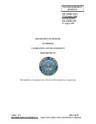
<strong>MIL</strong>-<strong>STD</strong>-<strong>1629</strong>Awhere:C* = Criticality number for the item.n = The failure modes in the items that fall undera particular criticality classification.j = Last failure mode in the item under the criticalityclassification.4. Criticality matrix. The criticality matrix provides ameans of identifying <strong>and</strong> comparing each failure mode to all other failuremodes with respect to severity. The matrix is constructed by insertingitem or failure mode identification numbers in matrix locations representingthe severity classification category <strong>and</strong> either the probability ofoccurrence level or the criticality number (Cr) for the item’s failuremodes. The resulting matrix display shows the distribution of criticalityof item failure modes <strong>and</strong> provides a tool for assigning correctiveI action priorities. As shown in Figure 102.2, the further along the‘ dia~onal line from the crigin the failure mode is recorded, the greaterthe criticality <strong>and</strong> the more urgent the need for implementing correctiveaction. The example criticality matrix in Figure 102.2 was constructedto shc~w how either the criticality number (Cr) or probability of occurrencelevel can be used for the vertical axis. The completed criticalitymatrix shall be included in the FMECA report, General Requirements, 4.5.5. Ordering data. The following details shall be specifiedin the appropriate contractual documents:a. Task 101 (see 1.1 of Task 102).b. Analysis approach (see 3 of Task 102).c. Failure rate data source(s) (see 3.2 of Task 102)if quantitative approach is specified.
<strong>MIL</strong>-<strong>STD</strong>-162!IA=w ao—.L&u0
MI I.-sTI)-I629AINCREASINGCRITICALITYHIGH) -A.d >t-//////’aṿ**-—E(LOW)—IIIIIISEVERITYCLASSIFICATION(hJcREAs ING LEVEL OF SEVERITY~)* NOTE:BOTH CRITICALITY NUMBER (Cr) AND PROBABILITY OFOCCURRENCE LEVEL ARE SHOWN FOR CONVENIENCE.Figure 102.2 Example of criticality matrixTASK 10224 November 1980
<strong>MIL</strong>-<strong>STD</strong>-<strong>1629</strong>ATASK 103FMECA-MAKNTH??IIBILITY INFORMATION1. Purpose. l%e purpose of the FMECA+naintainability informationanalysis is to provide ~rly criteria for maintenance planninganalysis (MPA), logistics support analysis (LSA), test planning,inspection <strong>and</strong> checkout requirements, <strong>and</strong> to identify maintainabilitydesign features requiring corrective action.1.1 Application. The FMECA-maintainability informationanalysis, Task 103, supplements the FMEA, Task 101, <strong>and</strong> shall not beimposed without imposition of Task 101.‘1.2 ‘-. Planning for the FMECA-maintainability informationanalysis includes the contractor’s procedures for assuring thecoincident use of this analysis when logistic support analysis in accordancewith <strong>MIL</strong>-ST&1388 <strong>and</strong> the maintenance planning analysis inaccordance with <strong>MIL</strong>-sTD-2080 are required by contract.2.-Mcurnents referenced in Task 103:STANDARDSMilitary<strong>MIL</strong>-<strong>STD</strong>-2080 Maintenance Plan Analysis for Aircraft <strong>and</strong>Ground Support Equipments3. FMECA-xuaintainability information worksheet. Documentationof the maintainability information is accomplished by completing theapproved FMECA-maintainability information worksheet. An example of anFM’ECA-maintainability workshee~ format is shown in Figure 103.1.Completed worksheets shall be included in Che FMECA report, GeneralRequirements, 4.5, following the FMEA worksh+t for the same indenturelevel. The following information is the same as that given in the FMEAworksheet <strong>and</strong> shall be transferred to the FMECA-maintainability informationworksheet:a. Identification numberb. Item/functional identificationc. Functiond. Failure modes <strong>and</strong> cduscsc. Failure effects (Jocal, next higher level, end)f. Severity classificaLioIlTASK 103
<strong>MIL</strong>-<strong>STD</strong>-<strong>1629</strong>A3*1 Failure predictability. Enter information on knownincipient failure indicators (e.g., operational performance variations)which are peculiar to the item failure trends <strong>and</strong> permit predictingfailures in advance. When a failure is predictable in advance, describethe data that must be collected, how it will be used to predict failure,<strong>and</strong> identify any tests or inspections that may be accomplished to detectevidence of conditions which could cause the failure mode.. .3.2 Failure detection means. Identify how each failure modewill be detected by the organizational level maintenance technician <strong>and</strong>to what indenture level they will be localized. Describe the method bywhich ambiguities are resolved when more than one failure mode causesthe same failure indication. Describe any monitoring or warning devicethat will provide an indication of impending failure <strong>and</strong> any plannedtests or inspections which could detect occurrence of the failure mode.Identify to what indenture level failures can be isolated by the use ofbuilt-in-test features <strong>and</strong> indicate when ancillary test equipment willbe required for fault isolation.3.3 Basic maintenance actions. Describe the basic actionswhich, in the analyst’s judgement, must be taken by the maintenancetechnician to correct the failure. Identify the special design provisionsfor modular replacement <strong>and</strong> tileprobable adjustmcn~ <strong>and</strong> calibril&iunrequirements following repair.3.4 Remarks. Any pertinent remarks pertaining to <strong>and</strong> clarifyln~any other columns shall be noted. Notes regarding recommendations fordesign improvement shall be recorded <strong>and</strong> further amplified in the FMECAreport, General Requirements, 4.5.4. Ordering data. The following details shall be specifiedin the appropriate contractual documents:a. Task 101 (see 1.1 of Task 103).h. Logistic support analysis (See 1.2 of Task 103).c. Maintenance planning analysis (see 1.2 of Task 103).TASK 103—24 November 1980
MI L-<strong>STD</strong>-<strong>1629</strong>Aua~owc oua2m cQ k.4u +LJbaE1-2 zwJ!0zw >w-1w az w01TASK 103If)?-?24 November 1980’
.--— .-—--— , --—— ——— —.TASK 104DAMAGE MODE AND EFFECTS ANALYSIS1. I’urpose. The purpose of the damage mode <strong>and</strong> e~fectsanalysis (DMEA) iS to provide early criteria for survivability <strong>and</strong>vulnerability assessments. The DMEA provides data related to damagecaused by specified threat mechanisms <strong>and</strong> the effects on weapon systemoperation <strong>and</strong> mission essential functions.1.2 Application. The MEA, Task 104, utilizes the results ofTask 101, <strong>and</strong> shall not be imposed without imposition of Task 101.~,: I’lani’i’in&İ’larming LlieWIIL4 i~lcludeb the contLacLoK”isprocedures for assuring the timeliness of the analysis <strong>and</strong> its utilizationin the vulnerability assessments of the weapon system.2. Analysis approach. The DMEA is an expansion of the FMEA——to include the generation of data reclui.recifor vulnerability assessments.It is prim3ri2y a~~li~abl~ to new weapan sysLem acquisitions but may beapplied to developed (existing) weapon systems where data is rec]uired toprovide criteria for a survivability enhanccrncnt program.2.1 New weapon systems. The DMEA is an expansion of the FMEAconducted <strong>and</strong> maintained for the weapon system design during conceptual,validation, <strong>and</strong> full scale development. The LV4EA shall consider allfailure modes <strong>and</strong> damage modes that can occur to each item <strong>and</strong> theeffect each has on the weapon system. ‘l’herelationship between theweapon sysLem essential f~Jnctions, mi.s%~on capabilities, hnst.1.l.e threatcapabilities, <strong>and</strong> hostile weapon effects shall be analyzed to providedesign criteria for survivability enhancement.2.2 Developed weapon s~stems. When specified, a DMEA is——conducted to identify all subsystems <strong>and</strong> components in a developed(existing) weapon system to the 1.CVC1 defined by the procuring agency.The DMEA is used to provide data related LO L]leimpact of EngineeringChange Proposais (ECPs) <strong>and</strong> retrofit propr~ms on rota] w[’apon ~ystc>msurvivab~lity. Threats should be periodi~:ll~~;●ssessed to duterninfi j[”the weapon system is still capable of operaLing effectively in a hostileenvironment,
.<strong>MIL</strong>-<strong>STD</strong>-<strong>1629</strong>AIall identified operation <strong>and</strong> mlSS~On essentia] sl~~systems <strong>and</strong> component~.The the of damage’mode that each component can experience (i.e., fire,explosion, engine fuel ingestion, tOXiC fumes, smoke-corrosive materials,etc.) <strong>and</strong> the primary <strong>and</strong> secondary damage effects to which each componentcan be exposed shall be identified. Each nonessential component alsoshall be examined to determine if a hazardous environment may be createdby its sustaining the type or level of damage identified. This shallalso include any cascading effect on other subsystems from an initialsystem or component response. The essential components that may beexposed to the hazardous environments shall be identified..3.1 Weapon system operation <strong>and</strong> mission essential functions.The requirements for weapon system operation <strong>and</strong> mission essentialfunctions shall be determined for each mission phase <strong>and</strong> included in thefunctional narrative developed in 4. of Task 101. The weapon systemoperation <strong>and</strong> mission essential functions shall be established down tothe indenture level that individual subsystems <strong>and</strong> major componentsrequired to perform the function can be identified.3.3.2 Identification of critical components. Using the systemschematic or functional block diagram, the assigned severity codes, <strong>and</strong>the established weapon system operation <strong>and</strong> mission essential functions,each subsystem <strong>and</strong> major component required to perform each missionessential func:ion shall be identified. The reliability block diagramshall be used to identify subsystem <strong>and</strong> function redundancies. A criticalcomponents listing shall be included with the functional narrative <strong>and</strong>with the DMEA kwrksh(~ets In the FMECA report, Cenera~ Requirements, 4.5.4* DMEA worksheet. Documentation of the DMEA is accomplishedby completing the columns of the approved MEA worksheet. An example ofa DKEA worksheet forma&-is shown in Figure 104.1. Completed DMEA worksheetsshall be included in the FMECA report, General Requirement, 4.S,following the FMEA worksheet for the same indenture level. The followinginformation is the same as given in the FMEA worksheet <strong>and</strong> shall betransferred to the DMEA worksheet:a. Identification numberb. Item/functional identificationc. Functiond. Failure modes <strong>and</strong> causese. Mission phase/operational modef, Severity classificationTASK 104—24 November 19801(?4-?
MTL-<strong>STD</strong>- <strong>1629</strong>A4\l Damage modes. All possible damage modes which couldresult from exposure to the specified threat mechanism(s) shall bedetermined through analysis of each subsystem, component, or Parts Theanalysis shall include both primary <strong>and</strong> secondary damage effects.Damage modes of individual item functions shall be postulated on thebasis of the stated mission requirements, specified threats, <strong>and</strong> systemdescriptions. The effects of the possible damage mode shall includeperformance degradation as well as total item failure. To assist inassuring that a complete damage mode analysis is performed, each damagemode <strong>and</strong> function ghall, as a minimum, be examined in relation to thefollowlng typical damage conditions.a. Penetrationb. Severedc. Shattered, crackedd. Jammede. Deformedg“ Burned out (i.e., electrical overload)h. Burn through (i.e., threat caused fires)4.2 Damage effects. The consequences of each assumed damagemode on item operation, function or status shall be identified, evaluated,<strong>and</strong> recorded. Damage effects shall focus on the specific block diagramelement which is effected by the damage condition under consideration.The damage mode under consideration may impact several indenture levelsin addition to the indenture level under analysis; therefore, “local,”“next higher level,” <strong>and</strong> “end” effects shall be evaluated.4.2.1 Local effects, Local effects concentrate specifically onthe impact an assumed damage mode has on the operation <strong>and</strong> function ofthe item in the indenture level under consideration. The consequencesoi each postulated damage mode affec~ii~g Liie item shall De describedalong wi:h any second-order effecls whici~ resul~s. P~Jtentidl cullditionswl}ere the damage of one item results in a c~~ntiitionalfailure probabilityor effect of a second item which differs fr-~)m the failure probability oreffect when the second item is considered independently shall be iden~ified.The purpose of defining local effects is TO provide a basis for ev.al~latinp,corlpensating pr:)~-isions <strong>and</strong> for recommerlci;lj;:;urviv:ibi 1 ity enhancement ,It is possii)ie ior the “local” effect. L(J ‘h!: t?)t- 4am:3fic- mnc{e itself..
M1l,-STi)-<strong>1629</strong>A4.2.2 Next hfgher level. Next higher level effects concentrateon the impact an assumed damage mode has on the operation <strong>and</strong> functionof the items In the next higher indenture level above the indenturelevel under consideration. The consequences of each postulated damagemode affecting the next higher indenture level shall be described.-4.2.3 End effects. End effects evaluate <strong>and</strong> define the totaleffect an assumed damage m~de has on the operation, function, or statusof the uppermost system. The effect of each damage mode upon the essentialfunction(s) affecting weapon system operating capability <strong>and</strong> missioncompletion capability shall be determined. The end effect described maybe the result of a double failure. For example, failure of a safetydevice may result in a catastrophic end effect only in the event thatboth the prime function goes beyond limit for which the safety device iSset <strong>and</strong> the safety device falls. Those end effects resulting from adouble failure shall be indicated on the DMEA worksheets.4.3 Remarks. ~Y pertinent remarks pertaining to <strong>and</strong> clarifyingany other column in the worksheet line shall be noted. Notes regardingrecommendations f~r design iulpr~vement shall be recorded <strong>and</strong> fur~heramplified in tileFMECA report, General Requirements, 4.5. This entryalso may include a notation of unusual conditions, damage effects ofredundant items, recognition of particularly critical design features orany other remarks t}latamplify the line entry. Information shall beprovided that reasonable actions <strong>and</strong> considerations are or have beenaccomplished to enhance sllrvjvability through recommended desi~n changes.Infcrmat:on r>ro~~jd$~dsh~ll ~dd~~ss ~:~~~~ll~bing:a. EQW Those features of the design that relate tothe identified damage mode that minimize the vulnerabilitywith respect to the specified threat mechanisms;i.e., redundancy, separation of components, lines,<strong>and</strong> structure, elimination of fire paths, integralarmor, etc.b. Test. Those tests recommended to verify the designfeatures recommended or incorporated for survivabilityenhancement.c. History. Identification of previous testing <strong>and</strong>—.——.— -analysis rela~lng to this particular case which willbe used to support the validity.5. Ordering data. The frllo~’in~ details shall kc specifi~din the appropriate contractual documents:a. Task 101 (SQL 1.2 of Task 104),b. Threat mechanisms (see j. of Task 104).TASK 10424 I?ovvmber 198fl
NI 1.-[; 1’1)- 1(); ?!)Au0.-.mr-rv)——-. ______.____\-—..---— ---.————. -—. ....__—-..—-III. ..-,aE$-Cn+Ln-et_l- -------- .--. .—-——.._ ------ .-—.. -----._____ .,..
MIbST&<strong>1629</strong>ATASK 105FAILURE MODE, ~FECTS, ND CRITICALITY ANALYSIS PIAN1. Purpose. The purpose of the FMECA plan is to documentthe contractors planned activities implementing the Failure ~de~Effects, <strong>and</strong> (criticality Analysis Tasks.1.1 Interrelationship. The FMECA plan shall not be requiredunless Task 1~1 is required..1.2 Application. This plan is used to evaluate planned FMECATask efforts by a contractor prior to plan approval. When approved. bythe procuring activity, the plan is used for monitoring <strong>and</strong> evaluatingcontractor implementation of the FMECA tasks. When a Reliability ProgramPlan, as a selected task from <strong>MIL</strong>-<strong>STD</strong>-785, has been proposed by theprocuring activity, the requirements of this Task shall be satisfied byincorporating the FMECA plan in the Reliability Program Plan.STANDARDS2. Documents referenced in Task 10S:Military<strong>MIL</strong>-<strong>STD</strong>-470<strong>MIL</strong>-<strong>STD</strong>-780<strong>MIL</strong>-<strong>STD</strong>-785<strong>MIL</strong>-<strong>STD</strong>-1388<strong>MIL</strong>-<strong>STD</strong>-1591<strong>MIL</strong>-<strong>STD</strong>-2072<strong>MIL</strong>-<strong>STD</strong>-2080Vajntainability, Human Factors <strong>and</strong> SafetyWork Unit Codes for Aeronautical Equipment;Uniform Numbering SystemReliability Program for Systems <strong>and</strong> EquipmentDevelopment <strong>and</strong> ProductionLogistics Support AnalysisC)nAircraft, Fault Diagnosis, Subsystems,Analysis/Synthesis ofSurvivability, Aircraft; Establishment <strong>and</strong>Conduct of Programs forMaintenance Plan Analysis for Aircraft <strong>and</strong>Ground Support EquipmentsHANDBOOKSMilitary<strong>MIL</strong>-HDBK-217Reliability Prediction of Electronic Equipment “105-1
MI I,-ST1)-<strong>1629</strong>A3. Content. The FMECA plan shall describe the contractor’sprocedures for implementing the specified requirements of this st<strong>and</strong>ardupdating the F~CA to reflect design changes, <strong>and</strong> use of the analysisresults to provide design guidance. Sample worksheet formats, groundrules, analysis assumptions, identification of the lowest indenturelevel of analysis, coding system description, failure definitions, <strong>and</strong>identification of coincident use of the FMECA by the contractor’s reliabilityorganization <strong>and</strong> other organization elements shall be included in theplan.‘1,3.1 Worksheet formats. The contractor’s formats, whichorganize <strong>and</strong> document the FMECA <strong>and</strong> other analysis methods containedherein, shall include the information shown in the example formats,lnFigures 101.3, 102.1, 103.1, 104.1. The initial indenture level ofanalysis shall be identified (item name) on each worksheet, <strong>and</strong> eachsuccessive indenture level shall be documented on a separate worksheetor group of worksheets. A sample of the contractor’s worksheet formatsshall be included with the FMECA plan.3.2 Ground rules <strong>and</strong> assumptions. The contractor shalldevelop ground rules <strong>and</strong> analysis assumptions <strong>and</strong> include them in theFMECA plan. The ground rules shall identify the FMECA approach (e.g.,hardware, functional, or combination) , the lo~’rst indenture level to beanalyzed, <strong>and</strong> include general statements of v’hat constitutes a failureof the item in terms of performance criteria <strong>and</strong> allowable limits.Every effort should be made to ide~~tify ~[~d rec~rd al] ground rules <strong>and</strong>analysis assumptions prior to initiation of the analysis; however,ground rules <strong>and</strong> analysis assumptions may be added for any item ifrequirements change. Additional ground rules <strong>and</strong> analysis assumptionsshall be documented <strong>and</strong> separately identified for inclusion in the FMECAreport.3.3 Indenture level. The indenture level applies to thesystem hardware or functional level at which failures are postulated.Unless otherwise specified, the contractor shall establish the lowestindenture level of analysis using the foll~)wing guidelines:a. The lowest level specified in the LSA c<strong>and</strong>idate listto assure complete inputs for each 1.SA c<strong>and</strong>idate.b. The lowest indenture level at which items are assigneda catastrophic (Category I) or critical (CategoryII) severity classifica&ion category (see 4.4.3).c. The specified or intended maintenance <strong>and</strong> repairlevel for items assigned a marginal (Category III)or minor (Category lV) sevet-ity classificationcategory (See 4.4.3).TASK 10524 November 1980
MI1,-SI1)-<strong>1629</strong>A3.4 Coding system. For consistent identification of systemfunctions <strong>and</strong> equipment <strong>and</strong> for tracking failure modes, the contractorshall adhere to a coding system basep upon the hardware breakdown structure,work unit code numbering system of <strong>MIL</strong>-<strong>STD</strong>-780, or other similar unif~~numbering system. The coding system shall be consistent with the reliability<strong>and</strong> functional block diagram numbering system to provide complete visibilityof each failure mode <strong>and</strong> its relationship to the system. The contractorshall describe the coding system to be used in the FMECA plan.3.5 Failure definition. The contractor shall develop generalstatements of what constitutes a failure of the item in terms of performanceparameters <strong>and</strong> allowable limits for each specific output. Failuredefinitions shall be included in the ground rules submitted with theFMECA plan. The contractor’s general statements shall not conflict withany failure definitions specified by the procuring activity.3.6 Coordination of effort. The coincident performance <strong>and</strong>use of the FMECA by reliability <strong>and</strong> other porgram elements shall beidentified in the FMECA plan. Consideration shall be given to therequirements to perform <strong>and</strong> use the FMECA in support of a reliabilityprogram In accordance with <strong>MIL</strong>-<strong>STD</strong>-785, maintainability program inaccordance wi th MI1.-<strong>STD</strong>-47O, survi~~ahi]it~’,~v.d‘:ulnernbilit’;pToqraT, iraccordance with <strong>MIL</strong>-<strong>STD</strong>-2072, logistics support analysis in accordancewith <strong>MIL</strong>-<strong>STD</strong>-1388, maintenance plan analysis (MPA) in accordance with<strong>MIL</strong>-<strong>STD</strong>-2080, fault diagnosis analysis in general accordance with <strong>MIL</strong>-<strong>STD</strong>-1591, <strong>and</strong> other contractual provisions. The contractor shallidentify the program organization responsible for performing the FMECA<strong>and</strong> show how the FMECA results will be used by other organizationalelements to p~eCiucie duplication ot effort.3*7 Failure rate data sources. The failure rate data sourceshall be the same as that used for the other reliability <strong>and</strong> maintainabilityanalyses required by the contract. NIL-HDEK-217 shall be tl~eprimarysource of failure rate data for electronic parts. Failure rate data forparts not covered by <strong>MIL</strong>-HDBK-217 shall be selected from alternativedata sources. The failure rate data sources shall be identifi~d in theFMECA plan <strong>and</strong> shall be approved by the procuring activity prior- to USe.4. Ordering data, The followin g details s}lall -in the appropriate contractual documents:.-.,a. Task 101 (See 1.1 of Task 105).b. Other requirements as necessary for tai lorlng.i(’~i w}~(~t~ion with this.
—..-A 1<strong>MIL</strong>-<strong>STD</strong>-<strong>1629</strong>AAPPENDIXA10. GENERALAPPLICATION AND TAILORING GUIDE10.1 -“ This appendix provides notes for the guidance ofthe procuring activity In generating the contractual requirements for afailure mode, effects, <strong>and</strong> criticality analysis (FMECA)..10.2 Tailoring requirements. Each provision of this st<strong>and</strong>ardshould be reviewed to determine the extent of applicability. Tailoringof requirements may take the form of deletion, addition, or alterationto the statements in Sections 3 <strong>and</strong> 4 <strong>and</strong> any specified tasks to adaptthe requirements to specific system characteristics, procuring activityoptions, contractual structure, or acquisition phase. The tailoringFMECA requirements are specified in the contractual provisions to includeinput to the sratement of work, contract data item list (CDRL), <strong>and</strong>other contractual means.10.3 Duplication of effort. It is incumbent upon the procuringactivity to review the contractual requirements to avoid duplication ofeffort between the reliability program <strong>and</strong> other program efforts such assafety, maintainability, human engineering, test <strong>and</strong> evaluation, survivability<strong>and</strong> vulnerability, maintenance planning, <strong>and</strong> integrated logistics support.Identification of the coincident use of FMECA results by the reliabilityprogram <strong>and</strong> other disciplinary areas is required in the FMECA plan orother appropriate ,program documentation to avoid duplication of effortby the procuring activity <strong>and</strong> the contractor.20, REFERENCED DOCUMENTS (not applicable)30. DEFINITIONS (not applicable)40 GENERAL REQUIREMENTS40.1 Ordering data. The procuring activity shall specify thefollowing:a. Title, number <strong>and</strong> date cf this st<strong>and</strong>ard.b. Task number(s) required.c. FFIECA plan (Task 105) if required.d. Indenture level of analysis (4.3.3) required.e. Steps to be used in the FMECA process (4.4.2).f. FMECA report (4.5) if required.&A-1
M?L-sT~-<strong>1629</strong>A40.2 Data item descriptions (DID). The following listed DIDsprovide a source of possible data item description <strong>and</strong> format requirementsfor required data.SOURCE DATA REQUIREMENTS APPLICABLE DID✟●Task 105 Failure Mode, Effects <strong>and</strong> DI-R-7086Criticality Analysis (FMECA) PlanGeneral Failure Mode, Effects <strong>and</strong> D1-R-7085Requirements Criticality Analysis (FMECA) ReportSection 4-5<strong>and</strong> Task 10150• APPLICATION CRITERIA50.1 General considerations. This st<strong>and</strong>ard has been structuredLO facilitate the tailoring of ~CA requiraents based upon individualprogram needs. Program variables such as system complexity, funding,<strong>and</strong> schedule influence the level of detail <strong>and</strong> timing of the FMECA <strong>and</strong>must be considered when tailoring the requirements. All programs do notrequire the same level of detail <strong>and</strong> all programs should not wait untilfull scale development to implement the F?fECA requirements.50.1.1 Level of detail. The level of detail applies to thelevel of indenture at which failures are posLulaLed. Tile FMECA can beaccomplished at various levels of indenture from system to part leveldepending upon the information available <strong>and</strong> the needs of the program.The lower the indenture level, the higher the level of detail since morefailure modes will be considered. Th; choice of the level of indenturemust be compatible with the program COSt <strong>and</strong> schedule constraints <strong>and</strong>the system reliability requirements. A less detailed analysis which isavailable in time to contribute to system reliability is more valuablethan a more detailed analysis which is late <strong>and</strong> makes changes costly <strong>and</strong>unfeasible. In general, the FMECA should not be performed below tl~elevel necessary to identify critical items or to the level required bythe LSA c<strong>and</strong>idate list, whichever is lower. The depth <strong>and</strong> detail of theFMECA effort must be defined in appropriate contractual <strong>and</strong> programdocumentation..-50.1.2U!!@l” The objective of the l%ECA is to support thedecision making process. If the analysis fails to provide usable informationat or before e project decision pc~iI;:, LIlen it h:l.s made no c(~ntribu: ion<strong>and</strong> is untimely. The time-phasing of the F?IECA effort is important <strong>and</strong>should be identified in the FMECA plan to assure that analysis resultswill be available to support the project decision points during systemdevelopment. Since program cost <strong>and</strong> scl]edulktconstraints require thatavailable resources be used wllcre they arc most CDSt etfective, theearliest possible availability of FMECA results is important. so ll~at theimpact on cost <strong>and</strong> schedule can be minimized.
<strong>MIL</strong>-<strong>STD</strong>-<strong>1629</strong>A50.1.3 Intended use. The FMECA is potentially one of the mostbeneficial <strong>and</strong> productive tasks in a well structured reliability program.Since individual failure modes are listed in an orderly, organizedfashion <strong>and</strong> evaluated, the FMECA serves to verify design integrity,identify <strong>and</strong> quantify sources of undesirable failure modes, <strong>and</strong> documentthe reliability risks. FKECA results can be used to provide the rationalefor changes in operating procedures for ameliorating the effects or fordetecting the incipience of the undesirable failure modes. Although theFMECA is an essential reliability task, it supplements <strong>and</strong> supportsother engineering tasks through identification of areas in which effortshould be concentrated. The FMECA results are not only used to providedesign guidance, but they are used advantageously in <strong>and</strong> for maintenanceplanning analysis, logistics support analysis, survivability <strong>and</strong> vulnerabilityassessments, safety <strong>and</strong> hazards analyses, <strong>and</strong> for fault detection <strong>and</strong>isolation design. This coincident use of the FMECA must be consideredin FMECA planning <strong>and</strong> every endeavor made to prevent duplication ofeffort by the program elements which utilize FMECA results.50.2 FMEA (task 101~. The FMEA is an essential design evaluationprocedure which should not be limited to the phase traditionally thoughtof as the design phase. The ini~ial FMEA should be done early in theconceptual phase when design criteria, mission requirements, <strong>and</strong> conceptualdesigns are being developed to evaluate t]ledesign approach <strong>and</strong> tocompare the benefits of competing design configurations. The FMEA willprovide quick visibility of the more obvious failure modes <strong>and</strong> identifypotential single failure points, some of which can bc eliminated withminimal design effort. As the mission <strong>and</strong> design definitions becomemore refined, the FMEA can be exp<strong>and</strong>ed to successively more detailedlevels. When changes are made in system design to remove or reduce theimpact of the identified failure modes, the FMEA must be repeated forthe redesigned portions to ensure that all predictable failure modes inthe new design are considered.50.3 CA (task 102). The CA is a procedure for associatingfailure probabilities with each failure mode. Since the CA supplementsthe FMEA <strong>and</strong> is dependent upon information developed in that analysis,it should not be imposed without imposition of the FMEA. The CA isprobably most valuable for maintenance <strong>and</strong> logistics support orientedanalyses since failure modes which have a high probability of occurrence(high criticality numbers) require investigation to identify changeswhich will reduce the potential impact on rhe maintenance <strong>and</strong> logisticsupport requireme~l~s for the system. Since the criticality numbers arcestablished based upon subjective judgments, they sk)uld only be used asindicators of relative priorities.*44-‘3
M1l.-<strong>STD</strong>-l629A50.4 FFfECA-maintainability information (task 103). The FMECAmaintainabilityinformation analysis is ut~l~zed to provide early designcriteria for test methods, accessibility, <strong>and</strong> repairability for the itembeing analyzed. This analysis is an extension of the FMEA <strong>and</strong> is dependentupon FMEA generated information; therefore, the FMECA-maintainabilityinformation analyses should not be imposed without imposition of theFMEA . The identification of how each failure will be detected <strong>and</strong>localized by the operational level maintenance technician will provideinformation for evaluating the effectiveness of built-in-test. Descriptionsof the basic organizational level maintenance actions required forfailure localization <strong>and</strong> correction will identify Potential accessibilityproblems permitting early design correction. Th; failure mode listingwhich is included on the completed worksheets should be utilized to.provide this required data for both the maintenance plan <strong>and</strong> logisticssupport analyses.50.5 DMEA (task 104). The DMEA provides essential inputs forthe vulnerability assessment of a weapon system to aid in the identificationof deficiencies <strong>and</strong> the evaluation of designs for enhancing survivability.Since the DMEA utilizes the failure mode information from the FMEA, itshould not be imposed without imposition of the FMEA. The DMEA, likethe initial FMEA, should be done early in the conceptual phase to providedata related to the capability of the conceptual weapon system design LOsurvive the effects of the specified hostile Lllreats. Development ofthis data before weapon system design configuration is finalized willprovide significant survivability benefits with minimal impact on cost<strong>and</strong> schedule.50.6 Criticality number (C=) calculation example. Calculationof meaningful criticality numbers requires the use of specific failurerate <strong>and</strong> part configuration data. When part configurations are known,failure rate data can be obtained from the appropriate reliabilityprediction, field data from past systems of similar design <strong>and</strong> environment,?luse, or failure rate data sources such as <strong>MIL</strong>-HDBK-217. With knownfailure rates, the criticality number for an item is the number offailures of a specific type expected per million hours due to the item’sfailure modes under a particular severity classification as discussed jnTask 101. A failure mode criticality number, ~, for a particularseverity classification is given by the expression:(1)The item criticality number, CrJ under n particular sever~~y cl,lssifjcation,is then calculated by summing the Cm for each failure mode under thatseverity classification. This summation is given by the expressions:jcr=~ (Cm)n orn=]cr=z-jn= 16fl~lpt X i(l )n R = 1,2,3, ...j (2).-. .
<strong>MIL</strong>-<strong>STD</strong>-<strong>1629</strong>AWhere:C= “ Criticality number for the item.Cm = Criticality number for a failure mode under a particularseverity classification (see 4.4.3).fi= Conditional probability of mission loss given that thefailure mode has occurred.“(3= Failure mode ratio. The probability, expressed as a decimalfraction, that the part or item will fail in the identifiedmode.A = Part failure rate.PIt should be noted that failure rates are usually defined in terms offailures per million hours (fx10‘6) a[ld, for simplification purposes,equation (1) may be multiplied by a factor of 106 to eliminate anunnecessary degree of arithmetic precision in worksheet entries. Thatis, ic is easier to enter criticality number on the worksheets as 1.08than to enter 1.08 x 1o-6 or 0.00000108. Tl)e importance of the criticalitynumber is in providing a relative ranking of the failures or failuremodes <strong>and</strong> not in the absolute value of the riurner’ic.For example, the calculations for C,n<strong>and</strong> ~r for a given mission ph
MII,-<strong>STD</strong>-16:?9A(X3 = 0.5 for failure mode under severity classification Category IV.Find: Cm <strong>and</strong> C= for the mission phase under severity classificationCategory II.Let /3= 0.5 <strong>and</strong> t = 1.0 hour for the mission phase.Fora~: ~= ((hl~pt x 106) = (0.5x 0.3) (7.2 X 10⁻⁶) (1) x 106For a2: Cm = 6(+ x 106) = (0.5 X 0.2) (7.2 X 10⁻⁶) (1) x 106Acm = 0.72Then:Cr = E (~)n = 1.08 +0.72 = 1.80lA-Aorj 2Cr = Z (Balpt x 106) = En(Lu’jt x 106)n=ln=lCr = (6a1Apt x 106)+ (fh2Apt x 106)Cr = (0.5 x 7.2 x 10-6 x 1) (0.3+0.2) x 106Cr = (3.6 X 10⁻⁶) (0.5) X 106Cr = 1.80 under severity class~ficat:ion Category 11.‘,..t,
INSIRUCII ONS: In ● continuing effort to nmke w c~*~tion d-umente &t*r, *e DoD p~ri~ this form for u insubmitting comxnsnu end suggestioru for improwementwAllu~n ofmjlitary et<strong>and</strong>ardizetioa documenwsre&titadto-e~~0~. ~ formUMY ~ de~ched.fo~ed-g *@ ~- in~i-~t ~~ ~Ong tie~~ -e f~ NOT =flL@. -dnasikd. In b~k f4 be + Ss=ific - ~ble •~~t -icu~ probl- -u su* m wor~q whti rwJuhd interpre~tion, wes@o rigid, mstrictiw, JOOM,embiguow or -c inco=ptiible, ~d gi- Propoeed wordingchangeswtdchwould elleviate thepbleuu. Enterinbhk 6 any remarks notmisted toa ~~ificpemgrsphofthedocument.Ifblock7 m fiiled out,enscknowledgerncmt will be mded to YOU withinSO cbys to let YOU know thet Your comments were r=eiwd end are beingaotidered.AJ07’J5: ‘his form may not be UA to request copies of documents, nor to mqueat wei-m, dtitions, or chrification ofspecification requiremen~ on current contrscts. Comments submitted on this form do not corutitu- or imply ●utborizetinto weive eny portionofthereferenced document(8)ortoamend contractual requirements.(Fold dons thbhe)(Fold dow thk line)DEPAF?TMENT OF THE NAVYComm<strong>and</strong>ing Officer11111NONaval Air Engineering CenterSystems Engineering St<strong>and</strong>ardization Department(SESD) , Code 93Lakehurst . NJ 08733h 4OFFICIAL BUSINE=●ENALTY FOR ●RtVATE USE $300I BUSINESS Rf=-”” MAIL [I FIRST CLASS PERMIT NO 12503 wASHINGTON O C fPOHAGE WILL BE PAID BY THE DEPARTMENT OF THE NAVYPOSTAGEN6cEs64nvIF MAILEDUfu ITEOIN THESTATESComm<strong>and</strong>ing OfficerNaval Air Engineering CenterSystems Engineering St<strong>and</strong>ardization Department(SESD) . Code 93Lakehurst, NJ 08733ATTN :TJ?14(9322)
=ANDARDIZATION DC=JMEm IMPROVEMENT PROHKAL IIk MAME of SUOMDTWM3 onr3ANlaTMx 4. TYPE OF ORGANIZATION (Md wu}•1VENDOKc1 LmE mMAN UFACTLJRE RB. ●nO@LEM AREASa ●Omglwll WbIrnb@c<strong>and</strong> Wodtng:@OTHER (**): .1.*e. RMmmond8tion:). REMARKSb. NAME OF SUSMITTER Lt. P&wt, Ml) - Oetknd b. WORK TELEPHONE NUW~ER (/lU/U& AmcodC) - Optlofm. MAILING AOOR&SS (Str,#& City, StIB&, Zl? ~) - ~ 8. OA7E OF SUBMISSION (YYMMDD)
<strong>MIL</strong>3TD-<strong>1629</strong>ANotice 17 June 1983<strong>MIL</strong>ITARY ~ANDARDPROCEDURES FOR PERFORMINGA FAILURE MODEEFFECTS AND CRITICALITY ANALYSISTo all holders of <strong>MIL</strong>-sTD-<strong>1629</strong>A1. The following pages of <strong>MIL</strong>+TD-<strong>1629</strong>A have been revised <strong>and</strong> supersede thepages listed:New PageDateSuperseded Page “Datev 24 November 1980Vf 7 June 19831 24 November 19802 7 June 1983103-1 thru 1034 7 June 19831034 7 June 1983A3 7 June 1983AA 7 June 1983v, Reprinted w/o changeVf 24 November 19801 Reprinted w/o change2 24 November 1980103-1 thru 103-3 24 November 1980NewAd 24 November 1980AA 24 November 19802. Make the following pen <strong>and</strong> ink changes:a. Page 105-1, aragraph 2, change title of <strong>MIL</strong>-<strong>STD</strong>-2080 to “MaintenanceEngineering blanning <strong>and</strong> Analysis for Aeronautical Systems,Subsystems, Equipment <strong>and</strong> Support Equipment.”b. Page 1053, paragraph 3.6, Itne 2, change “POR(3MM” to “PROGRAM.”c. Page AA, paragraph 50.7, line that starts with “For az: addpa~nthesis befo-reB.3. RETAIN THIS NOTICE AND INSERT BEFORE TABLE OF CONTENTS.4. Holders of <strong>MIL</strong>-sTD-<strong>1629</strong>A will verify that the page changes indicated heninhave been entered. Thfs notice will be retained as a check sheet. Thtsissuance is a separate publication. Each notfce is to be retained by stockingpofnts until the Military St<strong>and</strong>ard is completely revised or canceled.Custodians:Amy - CRAir Force -17Preparing Activfty:Navy -AS(Project No. RELI-0037)Review Activities:Navy -SH, OSAmy -EA, AR———— - .
.<strong>MIL</strong>-<strong>STD</strong>-<strong>1629</strong>AParagraph4.3.14.3.24.3.34.3.44.3.54.3.64.44.4.14.4.1.14.4.1.24.4.1.34.4.1.44.4.24.4.34.54.5.14.5.24.5.2.14.5.2.25.5.1Tasks101102103104105CONTENTS (Continued)Worksheet formats . . . . . . . . . . . . . . .Ground rules <strong>and</strong> assumptions . . . . . . . . .Indenture level . . . . . . . . . . . . . . . .Coding system. . . . . . . , . . . . , . . . ,Failure definition . . , . . . . . . . . . . .Coordination of effort . . . . . . . . . . . .General procedures. . . . . . . . . . . . . .Contributing information . . . . . . . . . . .Technical specifications <strong>and</strong> development plans.Trade-off study reports . . . . . . . . . . . .Design data <strong>and</strong> drawings . . . . . . . . . . .Reliability data . . . . . . . . . ..OO..FMEAprocess. . . . . . . . . . . . . . , . .Severity classification . . . . . . . . . . . .FMECAReport. . . . . . . . . . . . . . . . .Sunmaryl?eliabili~y”c~i~t~ai ~t~m”l~s~s”, ”,”o”.”e”c”ooeCategory I <strong>and</strong> Category 11 failure mode Ifst .Single failure points lfst . . . . . . . . . .DETAIL REQUIREMENTS . . . . . . . . . . . , . .Tasks. . . . . . . . . . . .0 . . . . . . . .FAILURE MOI)EAND EFFECTS ANALYSIS . . . . . . .CRITICALITY ANALYSIS . . . . . . . . . . . . .FMECA44AItJTAINAf31LITYINFORMATION . . . . . . .DAMAGE MODE AND EFFECTS ANALYSIS ● . . . . . .FAILURE MOf)E,EFFECTS, AND CRITICALITYANALYSIS PLAN. . . . . . . . . . . . . . . .Page6666777778888910101011111111101-1102-1103-1104-1.105-1FigureTask 101FXGURES101.1 Example of a functional ’block diagram . . . . . 101-9101.2 Example of a reliability block dfagram . . . . 101-10101.3 Example of FMEA worksheet format . . . . . . . 101-11Task 102102.1 Example of CA worksheet format . . . . . . . . 102-5102.2 Example of criticality matrix . . . . . . . . . 102-7vI
<strong>MIL</strong>-<strong>STD</strong>-<strong>1629</strong>ACONTENTS (Continued)FigurePageTask 103103.1Example of FMECAinaintainabil ity informationworksheet form. . . . . . . . . . . . . . . 103-4Task 104104.1Example of damage mode <strong>and</strong> effects analysfsformat. . . ● . . . . ● , . . . . , . . . . 104-5APPENDIXAPPENDIX A.APPLICATION AND TAILORING GUIDE . . . . . . . . A-1Paragraph10.10.110.210.320.30.40.40.140.250.50.150.1.150.1.250.1.350.250.350.450.550.650.7GENERAL. . . . . . . . . . . . . . . . . . . . A-7Scope. . . . . . . . . . . . . . . . . . . . . A-1Tailoring requirements . . . . . . . . . . . . A-1Duplication of effort . . . . . . . . . . . . . A-1REFERE?KED DOCUMENTS (not applicable) . . . . . A-1DEFINITIONS (nonapplicable) . . . . . . . . . A-1GENERAL REQUIREFIENTS . . . . . . ● . ● . . . . A-1Ordering data. . . . . . . . . . . . . . . . . A-1Data item descriptions (DID) . . . . . . . . . A-2APPLICATION CRITERIA . . . . . . . . . . . . . A-2General considerations . . . . . . . . . . . . A-2Level of detail . . . . . . . . . . . . . . . . A-?Timing. . . . . . . . . . . . . . . . . . . . A-2Intended use. . , . . . . . . . . . . . . . . A-3FMEA(task 101) . . . . . . . . . . . . . . .. A-3CA(task 102). . . . . . . . . . . . . . . . . A-3FMECA+naintainabllity information (task 103) . A-3DMEA(task 104) . . . . . . . . . . . . . . . . A-4FMECAPl an (task 105).... . . . . . . . . . A-4Criticality number (cr) calculation example . . A-4./’7 June 1983viJ
<strong>MIL</strong>-<strong>STD</strong>-<strong>1629</strong>A1. SCOPEl.l Sco e. This st<strong>and</strong>ard establishes requirements <strong>and</strong> proceduresfor performing+a ailure mode, effects, <strong>and</strong> criticality analysis (FMECA) tosystematically evaluate <strong>and</strong> document, by Item failure mode analysis, thepotential impact of each functional or hardware fajlure on mission success,personnel <strong>and</strong> system safety, systen performance, maintainability, <strong>and</strong>maintenance requirements. Each potenttal failure is ranked by the severity ofits effect in order that appropriate corrective actions may be taken toeliminate or control the high risk items.1.2This st<strong>and</strong>ard applies to the acquisition of alldesignated DoDY*sys ems <strong>and</strong> equipment. It pr~marjly applies to the programacttvtty phases of demonstration <strong>and</strong> validation <strong>and</strong> full-scale engineeringdevelopment; e.g., design, research <strong>and</strong> development, <strong>and</strong> test <strong>and</strong> evaluation.This st<strong>and</strong>ard also can be used during production <strong>and</strong> deployment to analyze thefinal hardware design or any major modifications. The FMECA tasks containedin this st<strong>and</strong>ard apply to all items of equipment. This st<strong>and</strong>ard does notapply to software. Appendix A contains additional application <strong>and</strong> tailoringguidelines.1.3 Numbering system. The tasks are numbered sequentially as theyare introduced into this st<strong>and</strong>ard with the fjrst task being number 101.1.4 Revisions.1.4.1 St<strong>and</strong>ard. Any general revision of this st<strong>and</strong>ard which resultsin a revision of sections 1, 2, 3, or 4 will be indicated by revision letterafter this st<strong>and</strong>ard number, together with date of revision.1.4.2 Tasks. Any revisions of FMECA tasks are indicated by a letterfollowing the ~ For example, for task 101, the first revision is 101A,the second revision is 101B. Mhen the basic document is revised, thoserequirements not affected by change retain their existing date.1.5referenced by2. REFERENCED DOCUMENTSMethod of reference. The tasks contained herein shall bespecifying:a. This st<strong>and</strong>ard number.b. Task number(s).c. Other data as called for in individual task.2.1 Issues of documents. The following documents of the issue heffect on the date of Invitation for bid or request for proposal, arereferenced in this st<strong>and</strong>ard for information <strong>and</strong> guidance.1————.=——.ss? a>~—_—_—._—— .—————._—_—_. ..— -=—->._—. .
<strong>MIL</strong>-<strong>STD</strong>-<strong>1629</strong>ASPECIFICATIONSMilitary4<strong>MIL</strong>-N-241OOManual, Technical; Functionally OrientedMaintenance Manuals for Systems <strong>and</strong> E@~ntSTAIIDARDSMilitary<strong>MIL</strong>-sTr)-280<strong>MIL</strong>-sTll-47fl<strong>MIL</strong>-<strong>STD</strong>-721<strong>MIL</strong>-<strong>STD</strong>-756<strong>MIL</strong>-<strong>STD</strong>-780<strong>MIL</strong>-<strong>STD</strong>-785<strong>MIL</strong>-<strong>STD</strong>-882<strong>MIL</strong>-<strong>STD</strong>-1388<strong>MIL</strong>-<strong>STD</strong>-1591<strong>MIL</strong>-<strong>STD</strong>-2072<strong>MIL</strong>-<strong>STD</strong>-2080HANDBOOKSMilitary<strong>MIL</strong>-HDRK-217<strong>MIL</strong>-HDBK-266Definitions of Item Levels, ItemExchangeability, Models <strong>and</strong> Related TermsMaintainability Program Requirements (forSystems <strong>and</strong> Equipment)Oefinitfons of Te?ms for Reliability <strong>and</strong>MaintainabilityReliability PredictionWork Unit Codes for Aeronaut~cal Equipment;Uniform Numbering SystemReliability Program for Systems <strong>and</strong>Equipment Development <strong>and</strong> ProductionSystem Safety Program RequirementsLogistics Support AnalysisOn Aircraft, Fault Diagnosis, Subsystems,Analysis/Synthesis ofSurvivability, Aircraft; Establishment <strong>and</strong>Conduct of Proqrams forMaintenance Engineering, Planning, <strong>and</strong>Analysis”the for Aeronautical Systems,Subsystems, Equipment <strong>and</strong> Support EquipmentReliability Prediction of ElectronicEquipBentApplication of Reliability CenteredMaintenance to Naval Aircraft, WeaponSystems <strong>and</strong> Support Equipment-(copies of specifications, st<strong>and</strong>ards, drawings, <strong>and</strong> publications requiredby contractors ~n connection with specific procumbent functions should beobtained from the procuring activity or as directed by the contractingofficer.)z~ne 19832
. ——<strong>MIL</strong>-<strong>STD</strong>-<strong>1629</strong>ATASK 103FMECA - MAINTAINABILITY INFORMATIONFMECAinalntainabtllty information supplies early criterta for~inte%%% arming Analysis (MPA), Logistic Support Analysis (LSA), testplannin , inspection <strong>and</strong> checkout requirements, <strong>and</strong> identifies maintainabilitydesign ! eatu~s that require corrective action, <strong>and</strong> supplies information forthe Reliability-Centered Maintenance (RCM) process required by<strong>MIL</strong>-HIBK-266(As).1.1 The FMECAmaintainabfl ity information requires data fromTask 103 shall not be done without first doing Task 101.1.2 Planning. Planning for the FMECA - maintainability information analysisincludes the contractor’s procedures for assurin the coincident use of thisanalysis when logistic support analysis in accor%ante with <strong>MIL</strong>-<strong>STD</strong>-1388,themaintenance planning analysis in accotiance with <strong>MIL</strong>-<strong>STD</strong>-2080(AS), <strong>and</strong>maintainability analysis in accordance with <strong>MIL</strong>-<strong>STD</strong>-470 am required bycontract,2. Documents Referenced in Task 103:STANDARDSMi1itaw<strong>MIL</strong>-<strong>STD</strong>-470<strong>MIL</strong>-<strong>STD</strong>-1388<strong>MIL</strong>-<strong>STD</strong>-2080(AS)Maintainability program requirements (forsystems <strong>and</strong> equipment)Logistics Support AnalysisMaintenance Engineering, Planning ~nd Analystsfor Aeronautical Systems, Subsystems, Equipment<strong>and</strong> Support EquipmentHANDBOOKS<strong>MIL</strong>-HIBK-266(As)Application of Reliability-Centered Maintenancein Naval Aircraft, Weapon Systems <strong>and</strong> SupportEquipment3. FMECA - Matntainabilfty Information Worksheet. Maintainabilityinformation is documented on the approved FPILCA- maintainability worksheet.Figure 103.1 is a sample worksheet. Cofi~leteworksheets will be included inthe FMECA report, &neral Requirwnents, 4.5, following the FPEA worksheet forthe same indenture level. The followlng infonnat~on can be found <strong>and</strong> copiedfmm the FhEA worksheet:a. Item Identification Numberb. Item NomenclatureC. Function103-1Task 1037 June 1983
<strong>MIL</strong>-<strong>STD</strong>-<strong>1629</strong>Ad. Functional Failure (Failure Mode (Task 701))-e. Engineering Failure Mode (Failure Causes (Task 101))f. Failure Effects (local, next higher level, end)9. Severity Classh. Mission Phase3.1 System/Subsystem Description. Provide a concise description of thesytem or subsystem in terms of Its general function <strong>and</strong> major assemblies orcomponents.3.2 Conpensatlng provisions. This entry shall specifically addressredundanc~es <strong>and</strong> protective Featuns in relation to functions <strong>and</strong> functionalfailures. An item is considered redundant if its purpose is to duplfcate thefunction of another item. Also list the protective or warning devices, orfail-safe desfgn, that act to mitfgate serious consequences upon failure of acritical item.3.3 Functions. Functions <strong>and</strong> subfunctions should be transferred from Task101 worksheets. A number shall be placed in the small column next to eachfunction. The first function wfll be numbered 1, the second 2, <strong>and</strong> so on.3.4 Functional Failures. Record the functional failure (failure mode fromTask 1~) l-unctlonaltailures shall be lettered alphabetically beqinningwith “A”.” Note that a function may have more than one functional failure(failure mode, Task 101).3.5 Engineering Failure Mode. Record the engineering failure modes (failurecauses from Task ~erfng failure modes shall be numbered beginnfngwith “l”. Note that ; functional faflure may have more than one engineeringfaflure mode (failure cause, Task 101).3.6 Mininum Equipment List. Specify if the aircraft or end item ofequipment can be dlspatched on its assigned mission with the analysis iteminoperative. If the answer is “yes”, specify artylimitation.3.7 Failure Detection Method. A description of the methods by whichoccurrence of a speclflc functional failure (failure mode) is detected <strong>and</strong>localized by the operator ormafntainance technician shall be recorded.Describe the warnfng devices, if applicable, <strong>and</strong> other indications which makeevfdent to the operator or technician that an item has malfunctioned orfailed. If no indication exists, state whether or not the undetected failurewill jeopardize the mission objectives or personnel safety, <strong>and</strong> if theundetected failure allows the item to remain operational in a safe state, asecond failure situation shall be explored to detennfne whether or not anindication will be evident to the operator or maintenance technician. Propercorrelation of an item malfunction or failure may require identification ofnormal, abnormal <strong>and</strong> incorrect indications. Nor%al indications are those thatare evident to an operator or maintenance technician when the item isoperating normally. <strong>Inc</strong>orrect indications are those that are evident to theoperator or maintenance technician when the item has malfunctioned or failed.Task 1037 June 1983 103-2.
<strong>MIL</strong>-<strong>STD</strong>-<strong>1629</strong>A3.8 Engineering Failure Mode MTBF <strong>and</strong> Remarks. Calculate <strong>and</strong> provide MTBFdata for each engineering failure mode (failure cause) developed as part ofTask 101. Also include any remarks pertaining to hnd clarifying any othercolumns. Notes regarding reconrnendations for design improvements shall berecorded <strong>and</strong> further amplified in the FMECA report, General Requirements, 4.5.3.9 Ordering Data. The following details shall be specified in theappropriate contractual documents:a. Task 101 (see 1.1 of Task 103)b. DI-R-7085c. DI-R-7086d. The Statement of hforke. Other requirements as necessary for tailoring.103-3Task 1037 June 1983
<strong>MIL</strong>-<strong>STD</strong>-<strong>1629</strong>A..2’Ilm.o.,id1-< xQ !AIj‘IIm“0L>..k..1 1131P-1.-TASK1037 June 1983103-4
-.<strong>MIL</strong>-<strong>STD</strong>-<strong>1629</strong>A//:150.1.3 Intended use. The FMECA is potentially one of the mostbeneficial <strong>and</strong> productive tasks in a well structu~d reliability program.Since individual failure modes are lfsted in an orderly, organized fashion <strong>and</strong>evaluated, the FMECA serves to verify desfgn integrity, identify <strong>and</strong> quantifysources of undesirable failure modes, <strong>and</strong> document the reliability risks.FMECA results can be used to provfde the rationale for changes fn operatfngprocedures for ameliorating the effects or for detecting the incipience of theundesirable failure modes. Although the FMECAfs unessential reliabilitytask, it supplements <strong>and</strong> supports other engineering tasks throughidentification of areas in which effort should be concentrated. The FMECAresults are not only used to provide design guidance, but they are usedadvantageously in <strong>and</strong> for maintenance plannfng analys~s, logfstics supportanalysis, survivability <strong>and</strong> vulnerability assessments, safety <strong>and</strong> hazardsanalyses, <strong>and</strong> for fault detectfon <strong>and</strong> isolation design. This coincident useof the FMECA must be considered in FMECA planning <strong>and</strong> every endeavor nade toprevent duplication of effort by the program elements which utilfze FMECAresults.50.2 I%IEA (Task 101). The FMEA is an essential design evaluationprocedure which should not be Iimfted to the phase traditionally thought of asthe design phase. The initial FMEA should be done early fn the conceptualphase when desiqn criteria, missfon requirements, <strong>and</strong> conceptual desiqns arebeing developed”to evaluate the desiaqnapproach <strong>and</strong> to compare the beneffts ofcompeting design configurations. The FMEA will provide quick visibility ofthe more obvious failure modes <strong>and</strong> identffy potential single failure points,some of which can be eliminated with minfmal design effort. As the missfon<strong>and</strong> design definitions become more refined, the FMEA can be exp<strong>and</strong>ed tosuccessively more detafled levels. When changes are made in system design toremove or reduce the impact of the identified failure modes, the FMEA must berepeated for the redesigned portions to ensure that all predictable failuremodes in the new design are considered.50.3 CA (Task 102). The CA fs a procedure for associating failureprobabilities with each failure mode. Since the CA supplements the FMEA <strong>and</strong>is dependent upon information developed in that analysis, it should not beimposed wfthout imposition of the FMEA. The CA is probably most valuable formaintenance <strong>and</strong> logistics support orfented analyses since failure modes whfchhave a high probability of occurrence (high criticality numbers) requirefnvestfgatfon to identify changes whfch will reduce the potential impact onthe maintenance <strong>and</strong> logfstic support requirements for the system. Since thecriticality numbers are established based upon subjective judgments, theyshould only be used as indicators of relative priorities.50.4 FMECA+naintainability information (Task 103). This analysis is anextensfon 0$ h A <strong>and</strong> IS dependent up~ generated fnfonnation;therefore, the ‘~ECA-maintainability information analyses should not befmosed without imposition of the FMEA. The identification of how eachfa!Iurewfll be detected <strong>and</strong> localized will provide information for evaluatingItem testability. The failure mode listing whfch is included on the completedworksheet should be utilized to provide this required data for logistlcssupport analyses (LSA), maintenance plan analysis (MPA), <strong>and</strong> reliabilitycente~d maintenance (RCPI).A-3
—<strong>MIL</strong>-<strong>STD</strong>-<strong>1629</strong>A50.5 DMEA (Task 104). The DMEA provides essential inputs for thevulnerability assessment of a weapon system to aid in the identification ofdeficiencies-<strong>and</strong> the evaluation of des_ignsfor enhancing survivability. Sincethe DMEA utilizes the failure mode information from the FMEA, it should not beimposed without imposition of the FMEA. The DMEA, like the initial FMEA,should he done early in the conceptual phase to provide data related to thecapability of the conceptual weapon system design to survive the effects ofthe specified hostile threats. Development of this data before weapon systemdesiqn configuration is finalized will provide significant survivabilitybenefits with minimal impact on cost <strong>and</strong> schedule.50.6 FMECA plan (Task 105). The FMECA plan provides the contractor’splans <strong>and</strong> activities for implementing the FMECA tasks. The plan is used bythe procuring activity to evaluate the planned FMECA task efforts, <strong>and</strong> whenapproved, is used for monitoring contractor Implementation of the tasks. Theplan can be required as a separate document submittal or it can be included aspart of the Reliability Program Plan. The FMECA plan includes a descriptionof the contractor’s procedures for implementing the tasks <strong>and</strong> provides a crossindex showing the relationship of coincident performance <strong>and</strong> use of the FPEAtasks to preclude duplication of ef[ort. Sample contractor formats used inperformance of each FMECA task are <strong>Inc</strong>luded as a part of each task specifiedin the contract statement of work.50.7 Criticality number (Cr) calculation example. Calculation ofmeaningful criticality numbers requires the use of specific failure rate <strong>and</strong>part configuration data. When part configurations are known, failure ratedata can be obtained from the appropriate reliability prediction, field datafrom past systems of similar design <strong>and</strong> environmental use, or failure ratedata sources such as <strong>MIL</strong>-I{DBK-217. With known failure rates, the criticalitynumber for an item is the number of failures of a specific type expected permillion hours due to the item’s failure modes under a particular severityclassification as discussed in Task 101. A failure mode criticality number,Cm, for a particular severity classification is given by the expression:cm= f3aApt(1)The item criticality number, C , under ais then calculated by summing [he Cm forclassification. This sunwnation is givenparticular severity classification,each failure mode under that severityby the expressions:Cr = Z (Cm)nn=lOr(2)7 June 1983A-4
<strong>MIL</strong>ITARY STANDARDML-<strong>STD</strong>-<strong>1629</strong>ANotlct 228 November 1984PRCUDURES FOR PERFORMINGA FAILURE MOtXEFFECTS AND CRITICALITY ANALYSISloanholders of <strong>MIL</strong>-<strong>STD</strong>-<strong>1629</strong>A1. The followlng pages of <strong>MIL</strong>-<strong>STD</strong>-<strong>1629</strong>A have been rev~sed <strong>and</strong> supersede thepages llsted:!!k!@x Date Superseded Page Datev 24 November 1980 v Reprinted uio changev! 28 November 1984 v! 7 June 1983A-1 28 Hovember 1984 A-1 24 November 1980A-2 28 November 1984 lieuA-3 28 November 1984 NewA-4 28 November 1984 A-2 24 November 19802, Make the followlng pen <strong>and</strong> Ink changes:k. Exlstlng page A-3, change page number to A-5.b. Exlst\ng page A-4, Change page number to A-6.ExlWng page A-5, change page number to A-7.;“ ExIstlng page A-6, change page number to A-8.3. RETAIN THIj NOTICE AND INSERT BEFORE TABLE OF CONTENTS.4. Holders of <strong>MIL</strong>-<strong>STD</strong>-<strong>1629</strong>A w1ll verffy that the page changes Indicatedherein have been entered, Thls n~t!ce vIII be retatned as a check sheet.Thi$ !ssuartce ts a separate publication. Each notice ~s to be retained bystock~ng points unt!l the Military St<strong>and</strong>ard Is completely revises or canceled.Custodians:Army - CRAtr Force - 17Preparing ActivityNavy - AS(Project No. RELI-0037)Review ActWltles:Navy - SH, 0sArmy - EA, ARAMSC N3388FSC RILI
<strong>MIL</strong>-<strong>STD</strong>-<strong>1629</strong>ACONTENTS (Continued)ParagraphPage4.3.14.3.24.3.34.3.44.3.54.3.64.44.4.14.4.1.14.4.1.24.4.1.34.4.1.44.4.24.4.34.54.5.14.5.24.5.2.14.5.2.25.5.1Tasks101102103104105Norksheetformats. . . . . . . . ● . . . ● ● ● ● ● ●Ground rules <strong>and</strong> assumptions . . . . . . . . . . . .Indenture level . . . . . . . . . . . . . . . . . . .Coding system . . . . . . . . . . . . . . . . . . .Failure definition . . . . . . . . . . . . . . . . ●Coordination of effort... . . . . . . . . . . . .General procedures . . . . . . . . . . . . ● . “ “ “Contributing Information . . . . . . . . . . . . . .Technical specifications <strong>and</strong> development plans . . .Trade-off study reports . . . . . . . . . . . . . .Design data <strong>and</strong> drawings . . . . . . . . . . . . . .Reliability data. . . . . . . . . ● . . . . . . . .FMEA process. . . . . . . . . . . . . . . . “ ● ● “Severity classification . . . . . . . . . . . . . . .FMECA Report. . . . . . . . . . . . . .. + ● . ● “Summary . . . . . . . . . . . . . . ● .0 . . “ “OReliability critical item lists . . . . . . . . . . .Category I <strong>and</strong> Category II failure mode list . . . .Single failure points list . . . . . . . . . . . . .DETAIL REQUIREMENTS . . . . . . . . . . . . ..*.oTasks . . . . . . . . . . . . . . . . .+*= . ● =FAILURE MODE AND EFFECTS ANALYSIS . . . . . . . . . .CRITICALITY ANALYSIS . . . . . . . . . . . . . . . .FMECA-MAINTAINABILITY INFORMATION . . . . . . . . . .DAMAGE MODE ANI)EFFECTS ANALYSIS . . . . . . . . . ●FAILURE MODE, EFFECTS, AND CRITICALITY ANALYSIS PLAN.FIGURES6666777778888910101010111111101-11o2-1o3-104-1o5-FigureTask 101101.1101.2101.3Task 102102.1102.2Example of a functional block diagram . . . . . . . .Example of a rellablllty block diagram . . . . . . .Example of FMEA worksheet format . . . . . . . . . .Example of CA worksheet format . . . . . . . . . . .Example of criticality matrix . . . . . . . . . . .101-9101-10101-11102-6102-7v
<strong>MIL</strong>-<strong>STD</strong>-<strong>1629</strong>A<strong>MIL</strong>-<strong>STD</strong>-<strong>1629</strong>ACONTENTS (Continued)F!gurePageTask 103103.1Task 104104.1APPENDIX A.Paragraph10.10.110.210.320.Example of FMECA-maintainability informationuorksheetformat. . . . . . . . . . . . . . . . ●Example of damage mode <strong>and</strong> effects analysis format .APPENDIXAPPLICATION AND TAILORING GUIDE . . . . . . . . . .GENERAL. . . . . . . . . . . . . . . . . . . . . .●Scope .*. .*.* 0==. .*Tallortng ;equ~remen&”. . . . . . . . . . . . . . ●Dupllcatlon of effort . . . . . . . . . . . . . . .REFERENCED DOCUMENTS (not applicable) . . . . . . .103-3104-5A-1A-1A-1A-1A-1A-14040.140.2GENERAL REQUIREMENTS . . . . . . . . . . . . ● . . . A-1Orderlngdata. . . . . . . . . . . . . . . . . . ● ● A-1Data Item descriptions (DID) . . . . . . . . . . . A-2●50.50.150.1.150.1.250.1.350.250.350.450.550.650.7APPLICATION CRITERIA . . . . . . . . . . . . . . . .General considerations . . . . . . . . . . . . . . .Level ofdetall . . . . . . . . . . . . . . . . . “Timing. . . . . . . . . . . . . . . . ..* .. .Intended use. . . . . . . . . . . . . . . ● . . .FMEA(tasklOl). . . . . . . . . . . . . . . . . .CA(task102L . . . . . . . . . . . . . . . . . .FMECA-maintainability information (task 103) . . . .DMEA(task 104) . . . . . . . . . . . . . . ...=FMECAPlan (task 105).... . . . . . . . . . . .Criticality number (Cr) calculation example . . .APPENDIX A FIGURESA-2A-2A-2A-2A-3A-3A-3A-3A-4A-4A-4FigureAlBasic card entry instructions . . . . . . . . . . .A-228 November 1984vi
.-<strong>MIL</strong>-<strong>STD</strong>-<strong>1629</strong>AAPPENDIX AAPPLICATION AND TAILORING GUIDE10. GENERAL10.1 W?!?” This appendix provides notes for the gufdance of theprocuring activity In generating the contractual requirements for a fa~luremode, effects, <strong>and</strong> criticality analysis (FMECA).10.2 Tailoring requirements. Each provision of this st<strong>and</strong>ard shouldbe reviewed to determine the extent of applicability. Tailoring ofrequirements may take the form of deletion, additio~, or alteration to thestatements In Sections 3 <strong>and</strong> 4 <strong>and</strong> any specified tasks to adapt therequirements to specific system characteristics, procuring activity options,contractual structure, or acquisition phase. The tal?orlng FMECA requirementsare specified in the contractual provisions to include input to the statementof work, contract data item list (CDRL), <strong>and</strong> other contractual means.10.3 Duplication of effort. It is <strong>Inc</strong>umbent upon the procuringactivity to review the contractual requirements to avoid duplication of effortbetween the reliability program <strong>and</strong> other program efforts such as safety,malnta~nablllty, human engineering, test <strong>and</strong> evaluation, survivability <strong>and</strong>vulnerability, maintenance planning, <strong>and</strong> Integrated logistics support.Identlficatlon of the coincident use of FMECA results by the reliabilityprogram <strong>and</strong> other disciplinary areas is required in the FMECA plan or otherappropriate program documentation to avoid duplication of effort by theprocuring activity <strong>and</strong> the contractor.20. REFERENCED DOCUMENTS (not applicable)30. DEFINITIONS (not applicable)40 GENERAL REQUIREMENTS40.1 Ordering data. The procuring activity shall specify thefollowtng:a. Title, number <strong>and</strong> date of this st<strong>and</strong>ard.b. Task number(s) required.c. FMECA plan (Task 105) if required.d. Indenture level of analysis (4.3.3) required.e. Steps to be used in the FMECA process (4.4.2).f. FMECA report (4.5) if required. Code A In block8 of DD1423 if preliminary draft is required. Anautomated LSAR output report LSA-060 or anonautomated LSAR report, if required. If anautomated LSAR output report is required, theinformation at figure Al must be specified.A-128 November 1984
HIL-<strong>STD</strong>-?629ALSA-060. LCN Master File.Basic Card Entry Instructions.---CARD COLUMN DESCRIPTION INSTRUCTIONS1 SelectIon Indicator M<strong>and</strong>atory entry of “S”.(SEL IND)2-4 Report SelectIon Number M<strong>and</strong>atory entry of “060” which is(RSN)report number identifying the outputreport requested.5 Report Control Code (RCC) M<strong>and</strong>atory entry of an alphanumericcode; “A’’-’’Z”,“0’’-’’9”,which willuniquely identify this reportnumber selection. If a trailer oroption card is associated with thtsreport selection, it must match theRCC on the basic slection card.(If necessary, instructions fortrailer cards will be providedby the requiring authority).78-18Type Card (TYPE)Sequence Code (SEQCD)Start Logistic SupportAnalysis Control Number(START LCN)M<strong>and</strong>atory entry of “A” (basiccard). If a listing of the entirecontent of the LCN Master File isdesired, no further data isrequired to be entered on thiscard with the exception of cc 35.Leave blank.Enter the LCN identifying thefirst Item to be included In thereport. It identifies the system,subsystem, or component for whichthe report is desired. Dataelement definitions (DEi))arecontained in appendix F of<strong>MIL</strong>-<strong>STD</strong>-1388-2A. See DED 197for a complete definition of LCN.19Alternate LCN Code (ALC) If the report is required for analternate design or maintenanceconcept of an associated LCN, enterthe ALC. See DED 023 for acomplete definition of ALC.28 November 1984FIG Al Basic card entry instructionsA-2
20-30Stop LCN<strong>MIL</strong>-<strong>STD</strong>-<strong>1629</strong>AEnter the Stop LCN to Indfcate thepoint where the LSAR ADP systemwill stop extracting Informationfrom the file. If no Stop LCN isentered, all data from <strong>and</strong>subordinates to the Start LCN willbe considered as applicable forthe report. See DED 197.31-3334353637Useable on Code (UOC)Service Designation CodeB SheetOption CodeHeader PrintOption (HEADER)Magnetic Tape OptionEnter the UOC for the model ofthe equipment for which thereport Is to be developed.The UOC must match a UOCenteredon the record of theStart LCN. Data not matchingthe UOC entered will be omittedfrom the report. A blankUOC will result in selectionof all UOCS within the specifiedStart <strong>and</strong> Stop LCNrange. See DED 536 for acomplete definition of UOC.Enter “A”, Army; “F”, AirForce; “N”, Navy; “M”, MarineCorps’ “O”, Other <strong>and</strong> “X”, allwhen the output report dealswith specific task related datato be reported <strong>and</strong> output reportheaders.M<strong>and</strong>atory entry of “F” toobtain the FMECA data only. An “F”entry wI1l always result in HeaderPrints.If the output is required tohave data element headers foreach record type, enter “X”.Leave blank.FIG Al (cent’d) Basic card entry instructionsA-328 November 1984
<strong>MIL</strong>-<strong>STD</strong>-<strong>1629</strong>A.40.2 Data ttem descriptions (DID). The following listed DIDs providea source of possible data Item description <strong>and</strong> format requirements forrequired data.SOURCE DATA REQUIREMENTS APPLICABLE DIDTask 105 Failure Mode, Effects <strong>and</strong> DI-R-7086Criticality Analysis (FMECA} PlanGeneral Failure Mode, Effects <strong>and</strong> DI-R-7085ARequirements Critlcallty Analysis (FMECA) ReportSection 4-5<strong>and</strong> Task 10150. APPLICATION CRITERIA50.1 General considerations. This st<strong>and</strong>ard has been structured tofacilitate the tailoring of FMECA requirements based upon individual programneeds. Program variables such as system complexity, funding, <strong>and</strong> scheduieinfluence the level of detail <strong>and</strong> timing of the FMECA <strong>and</strong> must be consideredwhen tailoring the requirements. All programs do not require the same levelof detail <strong>and</strong> all programs should not wait until full scale development toimplement the FMECA requirements.50.7.1 Level of detail. The level of detail applies to the level ofindenture at which failures are postulated. The FMECA can be accomplished atvarious levels of indenture from system to part level depending upon theinformation available <strong>and</strong> the needs of the program. The lower-the indenturelevel, the higher the level of detail since more failure modes will beconsidered. The choice of the level of indenture must be compatible with theprogram cost <strong>and</strong> schedule constraints <strong>and</strong> the system reliabilityrequirements. A less detailed analysis which is available in time tocontribute to system reliability is more valuable than a more detai?edanalysis which Is late <strong>and</strong> makei changes costly <strong>and</strong> unfeasible. In general,the FMECA should not be performed below the level necessary to identifycritical Items or to the level required by the LSA c<strong>and</strong>idate list, whicheveris lower. The depth <strong>and</strong> detail of the FMECA effort must be defined inappropriate contractual <strong>and</strong> program documentation.50.1.2 w- The objective of the FMECA is to support the declslonmaking process. If the analysis fails to provide usable information at orbefore a project decision point, then it has made no contribution <strong>and</strong> isuntimely. The time-phasing of the FMECA effort is important <strong>and</strong> should beidentified in the FMECA plan to assure that analysis results will be availableto support the project decision points during system development. Sinceprogram cost <strong>and</strong> schedule constraints require that available resources be usedwhere they are most cost effective, the earliest possible availability ofFMECA results is Important so that the impact on cost <strong>and</strong> schedule can beminimized.—28 November 1984*u.m. GovsnMMcwTPRINTIMG OF?ICC 1904-0ss+s0/10167A-4
NOTICE OFCANCELLATIONNOT MEASUREMENTSENSITIVE<strong>MIL</strong>-<strong>STD</strong>-<strong>1629</strong>ANOTICE 34 August 1998SUPERSEDINGNOTICE 228 November 1984<strong>MIL</strong>ITARY STANDARDPROCEDURES FOR PERFORMINGA FAILURE MODEEFFECTS AND CRITICALITY ANALYSIS<strong>MIL</strong>-<strong>STD</strong>-<strong>1629</strong>A, dated 24 November 1980, is hereby canceled. Users mayconsult various national <strong>and</strong> international documents for informationregarding failure mode, effects, <strong>and</strong> criticality analysis.Custodians:Army - CRNavy - ASAir Force - 17Preparing Activity:AF-17(Project RELI-0089)Review activities:Army – AR, EANavy - OS, SH, TDOSD - SEAMSC N/AAREA RELI