Reactive Power Controller Operating instructions
Reactive Power Controller Operating instructions
Reactive Power Controller Operating instructions

Create successful ePaper yourself
Turn your PDF publications into a flip-book with our unique Google optimized e-Paper software.
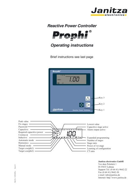
<strong>Reactive</strong> <strong>Power</strong> <strong>Controller</strong><strong>Operating</strong> <strong>instructions</strong>Brief <strong>instructions</strong> see last pageKey 3Key 2Key 1Peak valueFix stagesPasswordCapacitiveRequired capacitive powerCosinus ϕInductiveAutomatic modeHarmonicsManual modeTarget cos(phi1)Target cos(phi2)1 2 3 4 5 6 7 8 9 10 11 12 Errorcapcosϕ Qcindϕ1 ϕ2 learn 1:1... ProgLowest valueCapacitive stage activeAlarm output activeExpanded programmingNumber of stagesStage ratio<strong>Power</strong> of 1st stageLearning of configurationCT ratioDok Nr. 1.020.009.a Serie IIJanitza electronics GmbHVor dem Polstück 1D-35633 LahnauSupport Tel. (0 64 41) 9642-22Fax (0 64 41) 9642-30e-mail: info@janitza.deInternet: http://www.janitza.de
<strong>Reactive</strong> <strong>Power</strong> <strong>Controller</strong>ContentsReceipt Control 4Meaning of the symbols 4Hints for usage 4Product description 5Intended use 5Data protection 5Hints for maintenance 5Repairing and calibration 5Front foil 5Waste management 5Funktional description 6Measurement 6Switching of capacitor stages 6Switching outputs 6Net return 6Hints for installation 8Mounting place 8Measurement and supply voltage 8Sum current measurement 9Current measurement 9Installation and putting into service 10Measurement and supply voltage 10Current measurement 11Real power 11Switching outputs 12Transistor outputs 12Target-cos(phi) changeover 13Alarm output 13Check alarm output 13RS485 Interface (Option) 14Transmission protocols 14Bus structure 14Shielding 14Cable length 14Terminal resistors 14Removal of errors 15Service 16Display and use 17Automatic mode 17Manual mode 17Key functions 18Standard programming 19Target cos(phi) 19Current transformer ratio 20Learning of the configuration 21Stage power 22Stage ratio 22Switching outputs 23Delete peak and lowest values 24Expanded programming 25Fix stages 25Discharge time 26Disconnection pause 26<strong>Power</strong> station service 27Stage power 28Choke degree 28Voltage transformer ratio 29Harmonic thresholds 30Switching frequency 31Alarm output 32Alarm call 32Give a receipt for alarms 32Lower voltage (1) 33Overvoltage (2) 33Underscoring of the measurement current (3) 33Exceeding of measuring current (4) 33Insufficient capacitor output (5) 33Supply of real power (6) 33Harmonic thresholds (7) 33Overtemperature (8) 33Averaging time for the mean value cos(phi) 34Averaging time of reactive power 34Ventilator control 35Ventilation control 35Upper temperature limit 35Lower temperature limit 35Switching output 35Overtemperature disconnection 37Upper temperature limit 37Lower temperature limit 37Pause time 37Indication in manual mode 38Password 39Program password 39Enter password 39Change password 39Contrast 40Reset programming 41Connection configuration 42Correction angle 42Software release 43Serial number 43Serial interface (Option) 44Device address 44Transmission protocol 44Baud rate 45Modbus RTU 45Profibus DP V0 45Table Modbus 46Table Profibus 47Page 2= Key 1 = Key 2 = Key 3
<strong>Reactive</strong> <strong>Power</strong> <strong>Controller</strong>Display overview 48Measured value indications 48Display in standard programming 50Display in expanded programming 51Configuration data 53Setting range 53Manufacturer's presetting 53Technical data 54Ambient conditions 54Inputs and outputs 54Measurement 54Measurement accuracy 54Back Side 55Side view 55Short manual 56All rights reserved. No part of this manual may be reproducedor duplicated without the written permissionof the author. Any contraventions are punishable andwill be prosecuted with all legal means.No liability can be taken for the faultless condition ofthe manual or damage caused by the use of it. As failurescannot be avoided completely, we shall be verygrateful for any advice. We will try to remove any failuresas soon as possible. The mentioned software andhardware descriptions are registered trademarks in themost cases and are subjected to the regulations by law.All registered trademarks are property of the correspondingcompanies and are fully recognized by us.= Key 1 = Key 2 = Key 3Issue Note30.06.1999 First edition21.07.1999 Indication cos(phi)=0.00; Switching offixed stages.12.08.1999 Measurement accuracy, switchingfrequency.30.08.1999 Page 30, table of correction anglechanged.31.08.1999 Fuses and connection diagrams have beencorrected.12.11.1999 Switching in manual mode23.03.2000 Maximum and minimum storage all 15minutes.21.09.2000 Functional expansion.19.01.2001 Technical data and brief <strong>instructions</strong>added.20.03.2001 Generator mode = oFF.04.04.2001 RS485 interface.22.10.2001 Serial interface does not work at 50Hzswitching frequency.28.01.2002 Connection diagrams alarm output.12.08.2002 Address list Modbus expanded byharmonics U/I.22.08.2002 Description of password programming.23.09.2002 Measurement and supply voltage L-N.Page 3
<strong>Reactive</strong> <strong>Power</strong> <strong>Controller</strong>Receipt ControlIn order to ensure a perfect and safe use of the device, aproper transport, expert storage, erection and mountingand careful usage and maintenance are required. Whenit may be supposed, that a safe operation is no longerpossible, the device has to be put out of service and beprotected against unintentional putting into service.A safe operation can no longer be assumed, when thedevice• shows visible damage,• does not work in spite of intact net supply,• has been exposed to disadvantageous conditions for alonger time (e.g. storage out of the allowed climatewithout adaption to the room climate, dew etc.) or transportuse (e.g. falling from great height, even withoutvisible damage).Please test the contents of delivery for completion, beforestarting the installation of the device. All deliveredoptions are listed on the delivery papers.In the attached description doc. no.: 1.020.030.x all deliverytypes and options for the reactive power controllerProphi are listed.Attention! This manual also describes options andtypes, which were not delivered and therefore,do not belong to the contents of delivery.Hints for usageSafe and failure free operation can only be granted,when the device is operated according to this manual!This device may be put into service and used by qualifiedpersonnel according to the safety regulations and<strong>instructions</strong> only. Please mind the additional legal andsafety regulations for the respective application.Qualified personnel are persons, familiar with erection, mounting,putting into service and usage of the product and having the qualificationssuch as:• education or instruction / entitlement to switch, release,ground or characterize current circuits and devicesaccording to the standards of safety techniques.• education or instruction in the care and usage of suitablesafety equipment according to the standards ofsafety techniques.Meaning of the symbolsWarning of dangerous electrical voltage.This symbol shall warn you of possible dangers, which can occur during maintenance, putting into serviceand while usage.Protective wire connectionPage 4= Key 1 = Key 2 = Key 3
<strong>Reactive</strong> <strong>Power</strong> <strong>Controller</strong>Product descriptionIntended useThe reactive power controller Prophi together with externalcapacitor stages, serves for step by step controllingof the phase shift angle cos(phi) in 50/60Hz lowvoltage networks. Depending on the type of the reactivepower controllers Prophi, contactors or semi conductorswitches can be controlled directly.Additionally, the following electrical quantities are measuredand indicated:- Voltage L2-L3,- Current in L1,- Frequency,- Sum real power (Consumption/supply),- Sum reactive power (ind./cap.),- uneven current harmonic waves 1. - 19. in %,- uneven voltage harmonic waves 1. - 19. in %.The harmonic contents are related to the rated voltageor rated current.The connection is carried out on the back side via touchproof spring power terminals.Measurement and supply voltage are taken from themeasurement voltage and must be connected to thebuilding installation via a separation (switch or powerswitch) and an overcurrent protection (6,3A).The current measurement is carried out via a ../5A or../1A current transformer in one outer conductor.Hints for maintenanceBefore delivery the device is tested in various safetychecks and marked with a seal. If the device is opened,these checks must be repeated.There is no guarantee for devices, which are openedout of the manufacturing works.Repairing and calibrationRepairing and calibration work can be carried out in themanufacturing works only.Front foilThe cleaning of the front foil must be done with a softcloth using a common cleansing agent. Acid or acidicagents may not be used for cleaning.Waste managementThe device can be disposed as electronical waste accordingto the legal regulations and recycled.Data protectionThe data protection is carried out in a none volatilememory (EEPROM).Changed programming data are saved immediately.The relay outputs are suitable for contactor control, thetransistor outputs are provided for the control of fastswitching thyristor modules, switching at zero crossing.= Key 1 = Key 2 = Key 3Page 5
<strong>Reactive</strong> <strong>Power</strong> <strong>Controller</strong>Funktional descriptionMeasurementThe measurement is suited for 3 phase systems with orwithout neutral conductor for frequencies of 50Hz or60Hz. The electronical measurement system records anddigitalizes the effective values of voltage between L2and L3 (L-N Option) and the current in L1.In each second several snap check measurements arecarried out. As the current is only measured in oneouter conductor, and the voltage only between two outerconductors, the measured values, which are related toall three outer conductors, are exact for equal loadedouter conductors only.The following electrical quantities are calculated:Current and current harmonicsVoltage and voltage harmonicsReal power, sumApparent power,sum<strong>Reactive</strong> power, sum<strong>Reactive</strong> power for each stage<strong>Reactive</strong> current for each stageCos(phi),Net frequency.The following information can be indicated:Number of switchings of each stage,total connection time of each stage andthe inner temperature.Prophi measures the frequency of the measurement andsupply voltage and shows the average over 10 seconds.Switching of capacitor stagesProphi calculates the required reactive power to reachthe set target-cos(phi) from the current from one outerconductor and the voltage between two outer conductors.If the cos(phi) deviates from target cos(phi), externalcapacitor stages or transistor outputs are switchedon or off.In automatic mode the capacitor stages are switched inor off, when the required reactive power is higher orequal to the smallest stage power.If the power of the first capacitor stage is three times ashigh as the measured real power, all capacitor stagesare switched off.Switching outputsDepending on the variety of Prophi, relay or transistoroutputs serve as switching outputs.The relay outputs are suitable for controlling contactorsand the transistor outputs can switch thyristor modules,that switch in zero crossing of voltage.For relay outputs the time between two connections ordisconnections is set to two seconds. Transistor outputshave no limitation of the switching period.Net returnAfter net return, the set discharge time runs for therelay outputs. The transistor outputs do not mention thedischarge time.Page 6= Key 1 = Key 2 = Key 3
<strong>Reactive</strong> <strong>Power</strong> <strong>Controller</strong>ProphiDiagr.: Connection example, power factor controller with measurement and supply voltage L2-L3,12 relais outputs,target cos(phi) changeover and alarm output.Diagr.: Connection example, power factor controller with measurement and supply voltage L-N,12 relais outputs,target cos(phi) changeover and alarm output.= Key 1 = Key 2 = Key 3Page 7
<strong>Reactive</strong> <strong>Power</strong> <strong>Controller</strong>Hints for installationMounting placeThe reactive power controller Prophi is suited for mountingand operation in reactive power compensation systems.The connection is carried out on the back side via touchproof spring power terminals.EinspeisungSupplyEVU-MessungElectricity-MeterEinspeisungSupplyEVU-MessungElectricity-MeterVerbraucherConsumerProphiVerbraucherConsumerProphiRichtigCorrectFalschFalseMeasurement and supply voltageThe measurement is suited for 3 phase systems with orwithout neutral conductor. Measurement and supplyvoltage are taken from the measurement voltage andmust be connected to the building installation via aseparation (switch or power switch) and an overcurrentprotection (2A...10A).Attention!The operating voltage for the contactorsshould be taken from an outer conductor connectedto the reactive power controller.The reactive power controller measures and supervisesthe voltage between two outer conductors. If one ofthose two fails, the reactive power controller gets nomore measurement and operating voltage, and switcheson the capacitive stages after net return according tothe programmed times.If the third outer conductor is missing, this will not berecognized by the reactive power controller. If the contactorsare supplied by this outer conductor, the contactorscan attract simultaneously and without considerationof the discharge time after net return.EinspeisungSupplyVerbraucherConsumerProphiMessungMeasurementEVU-MessungElectricity-MeterProphiFalschFalseL/Lsiehe Typenschildsee type label0,01 .. 5Ak l L2 L3EinspeisungSupplyProphiVerbraucherConsumerEVU-MessungElectricity-MeterFalschFalseL1L2L3PEkl../5(1)A2 .. 10AVerbraucherConsumerAbb.: Anschluss der Mess- und Hilfsspannung zwischenL2-L3 und der Strommessung über Stromwandlers.Page 8= Key 1 = Key 2 = Key 3
<strong>Reactive</strong> <strong>Power</strong> <strong>Controller</strong>Sum current measurementIf Prophi is connected to a sum current transformer, thetotal transformation ratio must be programmed.Verbraucher 1Consumer 1Verbraucher 2Consumer 2LllLKkAK ALBK BLkKklEinspeisung 1Supply 1klProphiEinspeisung 2Supply 2Diagr. Measurement via sum current transformersAbb.: Anschluss der Mess- und Hilfsspannung zwischenL1-N und der Strommessung über Stromwandlers.Attention!For unequal load of the outer conductors, thecurrent should be measured in the outer conductor,which is loaded most heavily.Current measurementThe current measurement is carried out via ../5A or ../1A current transformers.If the current must be measured with an Amperemeteradditionally to Prophi, it must be connected in series.VerbraucherConsumerLKEinspeisungSupplylkAlProphikDiagr. Measurement with Amperemeter in series= Key 1 = Key 2 = Key 3Page 9
<strong>Reactive</strong> <strong>Power</strong> <strong>Controller</strong>Installation and putting into serviceMeasurement and supply voltageThe controller Prophi can be delivered in two connectionvarieties for the measurement and supply voltage.In the version measurement L-L, the measurement andsupply voltage must be taken from two outer conductors.In version measurement L-N, the measurementand supply voltage must be taken between outer conductorL and neutral N.Before connection, please ensure, that the local net conditionsmatch the data on type plate. The range of themeasurement and supply voltage is given by the typeplate and is connected via a fuse (2…10A, time lag type)Attention!The measurement and supply voltage mustcome from the low voltage net, which is supervised.The connected measurement and supply voltage maynot exceed the voltage, mentioned on type plate formore than 10% or underscore for more than 15%.To ensure, that the connected measurement and supplyvoltage is within the allowed range, please check thevoltage at the terminal with a voltmeter.Attention!Voltage, which is out of the indicated rangeon type plate can destroy the instrument.ProphiL1L2L3PEMessungMeasurementL/Lsiehe Typenschildsee type label0,01 .. 5Akk l L2 L3l../5(1)A2 .. 10AVerbraucherConsumerDiagr.: Connection of measurement and supply voltage(L2-L3) and current transformer.If the measurement and supply voltage is within theallowed range, Prophi indicates the voltage on the terminal.While measuring via voltage transformers, the voltagetransformer ratio must be programmed. Attention!The operating voltage for the contactors shouldbe received from an outer conductor connectedto the controller.Diagr.: Connection of measurement and supply voltage(L1-N) and current transformer.Page 10= Key 1 = Key 2 = Key 3
<strong>Reactive</strong> <strong>Power</strong> <strong>Controller</strong>Current measurementThe current transformer is connected to the clamps kand l (/5A or /1A) from the outer conductor L1.Please ensure during the installation of the current transformer,that the current transformer is passed by theconsumer current but not by the compensation current.The current can be measured by an Amperemeter tocompare it with the current indicated by Prophi to check.Please note, that the factory's presettings of the currenttransformer ratio is set to 10 and must be adapted to theexisting current transformer.If you should short-circuit the current transformer, theindicated value on Prophi must decrease to 0A.Examples for the setting of the current transformerExample 1Current transformer200A/5ASet Prophi to 40Real powerIf current and voltage are connected to Prophi accordingto the connection diagram, a positive real power isdisplayed in case of real power consumption. Real powerwith a negative sign in the indication points to the supplyof real power or an error of connection.Possible error:- Voltage and current are measured in the wrong outerconductor.- The current transformer clamps (k-l) are exchanged.Attention!For unequal load of the outer conductors, thecurrent should be measured in the outer conductor,which is loaded most heavily.Example 2Current transformer500A/1ASet Prophi to 500Example 3Sum current transformer 1000A+1000A/1ASet Prophi to 2000Attention!None earthed current transformer clamps canbe live.= Key 1 = Key 2 = Key 3Page 11
<strong>Reactive</strong> <strong>Power</strong> <strong>Controller</strong>Switching outputsThe reactive power controller Prophi can be equippedwith up to 12 switching outputs. The switching outputscan be equipped either with relay or transistor outputs.If a device is equipped with relay or transistor outputsit is not shown on display. The equipment can be seenin the connection diagram on the back of Prophi.Relay outputsCapacitor contactors can be connected to the relay outputsaccording to the connection example "Relay outputs".Transistor outputsSemi conductor switches, switching at zero crossing,must be connected to the transistor outputs of the reactivepower controller.The transistor outputs switch the voltage of an externald.c. net supply to the semiconductor switches.Prophi15-30VDCF0,2AC1max. 250V1ProphiC12..10A2132Diagr.:Connection example "Relay outputs"3Diagr.: Connection example "Transistor outputs"Check switching outputsPlease switch in the capacitor stages in manual mode:The inductive reactive power is decreased by the powerof the respective capacitor stage.Please switch off the capacitor stages in manual mode:The inductive reactive power is increased by the powerof the respective capacitor stage.TheAttention !For devices with relay or transistor outputs,there are different control voltages appliedto the switching outputs.Attention!relai and transistor outputs are live.Attention!If a switching frequency of 50Hz is programmedfor the transistor outputs, the serial interfacedoes not work!Possibility of errors:The outputs do not switch- Relay output defective.- Transistor output defective.The change of the reactive power is faulty- The current is measured incorrectly.- A wrong current transformer ratio is set.- The current is measured in the wrong outerconductor.- The voltage is measured in the wrong outerconductors.- The current transformer clamps k-l are exchanged.The reactive power does not change- The current transformer is installed at the wrongplace.- Switching outputs faulty.- The wrong control voltage is connected to theswitching outputs.Page 12= Key 1 = Key 2 = Key 3
<strong>Reactive</strong> <strong>Power</strong> <strong>Controller</strong>Target-cos(phi) changeoverVia the input target-cos(phi) changeover it can bechanged over between target-cos(phi1) and targetcos(phi2).If there is no voltage at the input, the target-cos(phi1)is active. If there is a 85 bis 265V AC connected to theinput, the target-cos(phi2) is active.Alarm outputThe alarm relay attracts in undisturbed operation, andthe contact of the alarm output is closed. If a disturbanceoccurs, the alarm relay releases and the contact isopened. Various events can be assigned to the alarmoutput via OR-logic interconnections. Each event is assignedto an alarm number, an alarm delay and alarmduration.Prophi1585 - 265V ACmax. 250V16Diagr.: Connection diagram target-cos(phi) changeoverIn the standard display (please see example), apart fromthe active channels and the actual cos(phi) also the activetarget-cos(phi) is indicated.ϕ2ϕ1T6,3A1314Diagr.: Connection diagram alarm output1 2 3cosϕindTarget-cos(phi1) is active.cosϕindTarget-cos(phi2) is active.ϕ11 2 3Actual cos(phi) meanvalueϕ2Actual cos(phi) meanvalueCheck alarm outputIf there is no alarm, the alarm relay attracts immediately.In order to trigger off an alarm, the threshold forovertemperature can be set to zero, for instance, andthe alarm relay releases immediately.ErrorProg= Key 1 = Key 2 = Key 3Page 13
<strong>Reactive</strong> <strong>Power</strong> <strong>Controller</strong>RS485 Interface (Option)Transmission protocolsTwo transmission protocols are available for the connectionto an existing field bus system:0 - Modbus RTU (Slave) and1 - Profibus DP V0 (Slave) .With Modbus protocol you can have access to the data oftable 1, and with Profibus protocol you can have accessto the data of table 2.Bus structureAll devices are connected in bus structure (line). In onesegment up to 32 participiants can be assembled. At theend and the beginning of each segment, the cable mustbe terminated by resistors. In Prophi you can activatethese resistors with two plug-ins.For more than 32 participiants you must use a repeater(line amplifier) to connect the single segments.Terminal resistorsIf Prophi is connected to the end of the bus cable, thebus cable must be terminated at this point with resistors.The required resistors are integrated within the Prophiand are activated in position ON.GNDONTermination392R 221R 392ROFF+5VB23A22ShieldingFor connections via RS485 interface, you need a protectedand twisted cable. To achieve a sufficient protectionresult, the shielding must be connected at both endsextensively to the housing or parts of the cabinet.GND10200740ProphiDiagr. Connection RS485 interface21Cable specificationsThe maximum cable length depends on cable type andtransmission speed. We recommend cable type A.Cable parameter Type A Typ BImpedance 135-165Ohm 100-130Ohm(f = 3-20MHz) (f > 100kHz)Capacity < 30pF/m < 60pF/mResistance < 110 Ohm/km -Diameter >= 0,34mm2 >= 0,22mm2(AWG22) (AWG24)Cable lengthThe following table shows the maximum cable length inmeters (m) for various transmission speed.Baud rate (kbit/s)Cable type 9.6 19.2 93.75 187.5 500 1500Type A 1200 1200 1200 1000 400 200Type B 1200 1200 1200 600 200 70Page 14= Key 1 = Key 2 = Key 3
<strong>Reactive</strong> <strong>Power</strong> <strong>Controller</strong>Removal of errorsDescription of the errorNo indication.Currenttoo little / too high.VoltageL2-L3 too little / too high.Real powertoo little / too high.Real power supply/consumptionexchanged.Cos(phi) = 0.00Cos(phi)too high / too little.Cos(phi) does not change,although all capacitorstages were switched in.Cos(phi) is indicated capacitiveon Prophi, but,nevertheless, the reactivepower meter measures reactivepower.Prophi only connectsstages, but does not disconnect.The outputs can only bedisconnected.Prophi shows a cos(phi) of0,2 - 0,4 capacitive.It does not work.Possible cause- Wrong measurement and supply voltageconnected.- Prefuse (10A time-lag type) has triggered.- Current measurement in the wrong outerconductor.- Wrong current transformer ratio.- Current out of measuring range.- Current transformer clamps are bridged.- One current transformer line is interrupted.- A current measuring device is connectedparallely.- Wrong voltage transformer ratio.- Uneven load of the outer conductors.- Wrong voltage transformer ratio.- Voltage and/or current are measured incorrectly.- Voltage and current are measured in thewrong outer conductors.- Voltage and/or current are measured incorrectly.- The current transformer connection (k-l) isexchanged.The measuring current is smaller but 10mA.The measuring voltage is interrupted.The current transformer clamps are bridged.- Voltage is measured incorrectly.- Current is measured incorrectly.- Real power is measured incorrectly.The current transformer is installed after themeasurement of the energy supplier.Current and voltage are connected in-correctly.The capacitor current is not detected by thecurrent transformer.Capacitive stages are faulty.The measurement and operating voltage isexceeded by more than 10%.Current measurement in wrong phase.L1 and L3 are exchanged.The device is defective.RemedyPlease check measurement and supplyvoltage.Please check current measurement.Please check voltage measurement.Please check current and voltagemeasurement.Please check current and voltagemeasurement.Please check current measurement.Please check current and voltagemeasurement.Check and correct connection.(Please see hints for installation)Check and correct connection.(Please see hints for installation)Check and correct mounting positionof the current transformer.Check capacitive stages.Check measurement and operatingvoltage.Check measurement and operatingvoltage.Send the device to the manufacturerwith an exact description of the error.= Key 1 = Key 2 = Key 3Page 15
<strong>Reactive</strong> <strong>Power</strong> <strong>Controller</strong>ServiceIf certain questions appear, which are not mentioned inthis handbook, please call us directly.To be able to support you, we require the followinginformation:- Device description (see type plate),- Serial number (see type plate),- Software Release,- Measurement and supply voltage and- Exact description of the error.You can reach us:Monday to Thursday from 07:00 to 15:00and on Friday from 07:00 to 12:00Janitza electronics GmbHVor dem Polstück 1D-35633 LahnauSupport:Tel. (0 64 41) 9642-22Fax (0 64 41) 9642-30e-mail: info@janitza.dePage 16= Key 1 = Key 2 = Key 3
<strong>Reactive</strong> <strong>Power</strong> <strong>Controller</strong>Display and useIn the front side of Prophi there is a digital indicationand three keys, with which you can question data andprogram the device.If you are in automatical mode, you can change betweenthe operating modes using key 1:automatic mode,manual mode,standard programming andexpanded programmingautomatic modemanual modestandard programmingexpanded programmingϕ1 ϕ2 learn 1:1... ProgIn standard programming often needed settings are carriedout such as current transformer ratio or the numberof stages.In expanded programming those settings are carried out,which are used not as often, such as discharge time orchoke degree.Automatic modeAutomatic mode is marked by the symbol .In automatic mode, there is:- the switching condition of capacitive stages,- the actual value of cos(phi) indicated,- Connection and disconnection of capacitive stages,- all 15 minutes saving ofpeak and lowest values,number of switchings of the capacitor stages andthe switching times of capacitor stages.- Indication of measured values using key 2 and 3.There are three possibilities to reach automatic mode:- after net return,- pressing key 1 for about 2 seconds,- pressing no key in programming mode for 1Automatic modecosϕind1 2 3ϕ1Actual value cos(phi)To reach the expanded programming from automaticmode, leaf through the standard programming using key1 until the symbol "Prog" appears. Confirm selectionwith key 2, and you are in expanded programming.Manual modeIn manual mode, you can switch in capacitor stagesusing key 3, and switch off capacitor stages using key2. The time between two switchings is only limited bythe programmed discharge time. If one stage shall beconnected in manual mode and a discharge time is running,the number and capacitor stage is flashing.If no capacitors are switched in manual mode, anautomatical jumpback to automatical mode is carriedout after 15 minutes.Connected stages1 2 3 4 5indk VArManual mode<strong>Reactive</strong> power= Key 1 = Key 2 = Key 3Page 17
<strong>Reactive</strong> <strong>Power</strong> <strong>Controller</strong>Key functionsAutomatic modeManual modeStandard programmingExpanded programmingProgshortPasswordChange mode2 secondsProg Prog2 secondsLeafshort longMeas. valuesMeas. valuesMeas. valuesMeas. valuesshortProgrammingMenueProgrammingMenueProgrammingMenueshort longProgrammingMenueProgrammingMenueProgrammingMenuelongshortProgrammingMenueProgrammingMenueConfirm selectionProgrammingSelect numbershort number +1long number -1Select numbershort number +1long number -1short value *10long value /10short value *10long value /10Page 18= Key 1 = Key 2 = Key 3
<strong>Reactive</strong> <strong>Power</strong> <strong>Controller</strong>Standard programmingIn the standard programming, the settings needed frequentlyare carried out, such as:- target-cos(phi1),- target-cos(phi2),- current transformer ratio,- learning of configuration,- power of the first capacitive stage,- stage ratio,- number of stages,- delete peak values (no indication).Target cos(phi)In automatic modeProphi tries to reachthe set target powerfactor by switching inor off the capacitorstages.cosϕindIt is possible to set a target-cos(phi1) and a targetcos(phi2).Devices without target-cos(phi) changeoveralways use the target-cos(phi1). Devices with an inputfor target-cos(phi) changeover switch to target-cos(phi2),ϕ1whenever the input is active.Range 0.80cap. - 1.00 - 0.80ind.Standard-Programmingϕ1 ϕ2 learn 1:1... ProgThe active target-cos(phi) is indicated in the measuredvalue indication for the actual-cos(phi).Example:1 2 3In delivery condition no password is programmed. Thechange from automatic mode into standard programmingis carried out without password protection.If a password is programmed by the user, the changefrom automatic mode to standard programming is carriedout only after password clearance.Change from automatic mode to standard programmingand back:Automatic modeshortPasswordStandardProgramming2 secondsAutomatic modeTarget-cos(phi1) is active.ProgrammingPress key for about 2seconds to select automaticmode.Press key 1 to leaf tomanual mode until indicationtarget cos(phi).cosϕindcosϕindϕ11 2 3ϕ1Automatic modeManual modeSelect the number to bechanged using key 2.The selected numberflashes.Change the selectednumber by pressingkey 3.cosϕindϕ1Target cos(phi1)Press key 1 for about 2 seconds. You return to automaticmode, and the changes are saved immediately.= Key 1 = Key 2 = Key 3Page 19
<strong>Reactive</strong> <strong>Power</strong> <strong>Controller</strong>Current transformer ratioAt the measuring inputof the currentmeasure-ment either /5A or /1A currenttransformers can beconnected. In order to get a correct current and powerindication, the current transformer ratio of the connectedcurrent transformer must be set to Prophi. If the currentis measured via a sum current transformer, the totalcurrent transformer ratio must be set.Example 1: Current transformer 500A/5AThe current transformer ratio is now calculated to500A : 5A = 100A ratio of 100 must be set on the device.Example 2: Current transformer 200A/1AThe current transformer ratio is calculated to200A : 1A = 200A ratio of 200 must be set on the device.Example 3: Sum current transformerTransformer 1 200/5ATransformer 2 400/5ASum current transformer 5+5/5AThe current transformer ratio is calculated to(200A + 400A) : 5A600A : 5A = 120ProgrammingExample: Current transformer ratio 1000Select indication forcurrent transformer ratiousing key 1.The automatic symboldisappears.ϕ1 ϕ2 learn 1:1... ProgCT ratioAutomatic modeSelect the digit to bechanged. The selecteddigit is flashing.Change the selecteddigit pressing key 3.kCurrent transformer ratios of more but 1000 are indicatedwith a decimal point automatically.Example: Current transformer ratio = 12001200 = 1.200kIndication on display "1.200k"Page 20= Key 1 = Key 2 = Key 3
<strong>Reactive</strong> <strong>Power</strong> <strong>Controller</strong>Learning of the configurationAfter installation of thecontroller there is thepossibility to learn andsave the configurationlearnwith the function"learn".Important requirements are:- The discharge time for capacitors is set to 60 seconds,when the device is delivered. For capacitors with longerdischarge times, the discharge time must be checkedand changed before using the "learn" function.- The current transformer must be flown through byconsumer and compensation current.- The measurement and supply voltage may not be takenfrom phase to N.- The compensation system must be ready for operation.The learning function of the controller is devided intotwo steps:Step 1 - Learning of the connection configurationHere the correction angle between current transformerand measurement and supply voltage is detected.Step 2 - Learning of the capacitor stagesHere the number of outputs and the stage power ofeach stage is detected.The following requirements are neccessary:- The switching of a capacitor stage must cause a changeof current of at least 50mA at current input.- The stage power of the stage to be learned must bebigger than 1% of the measuring range of the controller.Start learningGo to symbol learn usingkey 1.Select action (oFF, 1,2, 3) with key 3.learnStart learning with key1.The symbol learn flashes. The controller learns.During the learning the capacitor stages are switchedfor several times. The learning can only be interruptedby switching off the power factor controller.The duration of the learning procedure depends on thenet conditions, the number of capacitor stages and theset discharge time for the capacitors.When the learning procedure is finished, the detectedcorrection angle, in theexample 270°, is indicated.The learned characteristicsareProgsaved.After 60 seconds the controller changes to automaticmode. Pressing key 1 for 2 seconds, you reach automaticmode at once.Attention!After learning, the saved configurations must be checked,if they are plausible.Attention!After learning, the saved configurations must bechecked, if they are plausible.The following actions can be carried out:oFF - No learning.1 - Step 1, learning of the connection configuration.2 - Step 2, learning of capacitor stages.3 - Step 1 + 2, learning of the connectionconfiguration and capacitor stages.= Key 1 = Key 2 = Key 3Page 21
<strong>Reactive</strong> <strong>Power</strong> <strong>Controller</strong>Stage powerThe stage power is thepower of a capacitorstage. In the standardprogramming the stagepower can only be programmedfor the first stage. In the expanded programmingyou can set the stage power for each capacitorstage. If you only enter the stage power for the firstcapacitor stage, the other stages are fixed by the stageratio. The stage power of each capacitor stage can becalculated from the first stage and the correspondingstage ratio.RatioPage 220var - 9999kvarExample 1<strong>Power</strong> of the first capacitor stage = 10kvarStage ratio = 1:1:1:1:1....All following stages have the power: 10kvarExample 2<strong>Power</strong> of the first capacitor stage = 20kvarStage ratio = 1:2:4:8:8....The stages have the power:1. Stage = 20kvar2. Stage = 40kvar3. Stage = 80kvar4. Stage = 160kvar5. Stage = 160kvaretc.Example: Programming stage powerPlease select the indicationfor stage powerusing key 1.The automatic symboldisappears.ϕ1 ϕ2 learn 1:1... ProgStage powerAutomatick VArSelect the digit to bechanged using key 2.k VArThe selected digit isflashing.Change the digit bypressing key 3.If all numbers are flashing, the decimal point of the setnumber is moved.Stage ratioThe stage ratio statesthe ratio of the stagepower of the variouscapacitor stages. The1:1...power of the first capacitorstage serves as a reference. The stage ratio isprogrammable for each stage up to the fifth stage.Setting range : 0 - 9In the display only the stage ratio for the capacitorstages 2, 3, 4 and 5 are indicated. The stage ratio forthe first capacitor stage is always 1.Example 1The stage ratio is programmed to 1:2:4:8:8:8..., and inthe four digit-display, only the part "2:4:8:8" is indicated.1. capacitor stage5. capacitor stage1 . 2 . 4 . 8 . 8 . 8....Indicated on display.Example 2The stage ratio is programmed to 1:2:0:2:2:2.... In the4-digit display only the part "2:0:2:2" is indicated.1 . 2 . 0 . 2 . 2 . 2....Indicated on display.If the first capacitor stage has a power of 10kvar, thefollowing stages have the power:1. Stage = 10kvar2. Stage = 20kvar3. Stage = 0kvar4. Stage = 20kvar5. Stage = 20kvaretc.Example: Programming stage ratioPlease select the indicationof the stage ratiousing key 1.The automatic symboldisappears.Please select the digitto be changed usingkey 2. The selecteddigit is flashing.Change the selecteddigit by pressing key 3.1. capacitor stage5. capacitor stageϕ1 ϕ2 learn 1:1... ProgStage ratioAutomatic= Key 1 = Key 2 = Key 31:1...
<strong>Reactive</strong> <strong>Power</strong> <strong>Controller</strong>Switching outputsThe reactive powercontroller Prophi canbe equipped with up to12 switching outputs.Switching outputsExample 1: Prophi with 12 relay outputs10 of the 12 existing outputs shall be engaged.The programming and indication of the switching outputsis carried out in the menu standard programming.The switching outputs can be equipped with either relayor transistor outputs.If a device is equipped with relay or transistor outputsit cannot be read on display. The equipment can onlybe seen on the back side of Prophi in the connectionexample.Prophi is available in three varieties regarding theswitching outputs.1. Only relay outputs2. Only transistor outputs3. Relay and transistor outputs mixedPlease select the indicationof the switchingoutputs using key 1.The automatic symboldisappears.Please select the digitto be changed usingkey 2. The selecteddigit is flashing.Change the selecteddigit by pressing key 3.ϕ1 ϕ2 learn 1:1... ProgSwitching outputsAutomaticIn the menus of the standard programming, only thevariations 1 and 2 can be programmed.In mixed operation the switching outputs with smallernumbers are always the relay outputs.The relay outputs in mixed operation are programmedin the menu of standard programming, and the transistoroutputs are programmed in the menu of expandedprogramming. The programming of the transistor outputsis carried out indirectly via the stage power of theswitching outputs. For transistor outputs, to which nosemiconductor switch is connected, a capacitor powerof 0kvar is set.Switching outputsVariety 1 2 3 4 5 6 7 8 9 10 11 123R R R R3T T T T6R R R R R R R6T T T T T T T6R6T R R R R R R T T T T T T12R R R R R R R R R R R R R12T T T T T T T T T T T T TExample 2: Prophi with 3 transistor outputsPlease check, if 3 transistor outputs are programmed.The programming and indication of the switching outputsis carried out in the menu standard programming.Please go to the indicationof the number ofstages.The automatic symboldisappears.Only two stages areprogrammed!Select the digit to bechanged using key 2.The selected digit isflashing.Change the selecteddigit using key 3.ϕ1 ϕ2 learn 1:1... ProgSwitching outputsAutomaticT= Transistor outputsR= Relay outputsDiagr. Varieties of the switching outputs= Key 1 = Key 2 = Key 3Page 23
<strong>Reactive</strong> <strong>Power</strong> <strong>Controller</strong>Example 3: Prophi 6R6T with 6 transistor outputs and6 relay outputsTwo transistor outputs and 6 relay outputs shall be programmed.The programming of the relay outputs is carried out inthe menu standard programming, and the programmingof the transistor outputs is carried out in the menu expandedprogramming.1. step: Programming of the relay outputs.In standard programmingyou move to theindication of thenumber of stages usingkey 1. 6 stages are programmed,so no change is required.2. step: Programming of the transistor outputs.The programming of the transistor outputs is carriedout in the expandedprogramming.Please move to the expandedprogrammingProgusing key 1. Now presskey 2.In the expanded programmingappears themenu point "FixProgstages".Delete peak and lowest valuesPeak and lowest valuesof various measuredvalues are saved every15 minutes.The peak values andlowest values can only be deleted altogether.The following values are not deleted:Peak temperature value,Switching time of the capacitor stages andNumber of switchings per stage.Example: Delete peak valuesMove to indication forpeak and lowest valuesby pressing key 1.The automatic symboldisappears.Select delete with key 3.Text "on" is flashing.With key 1 you moveto the expanded programmingand activatedeletion.AutomaticUsing key 3, you reachthe indication stagepower.1k VArProgHere the stage (7) is selectedby pressing key2. Please confirm withkey1. One digit for thestage power is flashing.ProgIf this stage is engaged, the required stage power mustbe programmed by pressing the keys 2 and 3.Select the digit to be changed using key 2. The selecteddigit is flashing. Now change the digit using key 3.If all ciphers are flashing, the shown digit can be multipliedby 10 using key 3. Also the dimension of the unitcan be changed.7flashingVArPage 24= Key 1 = Key 2 = Key 3
<strong>Reactive</strong> <strong>Power</strong> <strong>Controller</strong>Expanded programmingIn the expanded programmingthose settingsare carried out,which are requiredvery rarely.ProgWith key 3 you can change between the indications.With key 1 the selected indication can be chosen forchanging.The following settings and readings can be carried out inexpanded programming:Fix stages,Discharge time,Disconnection pause of relay stages,<strong>Power</strong> station service,Stage power, 1. - 2. stage,Choke degree,Voltage transformer ratio,Harmonic table,Switching frequency of transistor stages,Alarm calls,Averaging time for reactive power,Averaging time of the mean value cos(phi),Fan control,Overtemperature disconnection,Indication in manual mode,Password,Contrast,Reset of programming,Connection configuration,Software release andSerial number.<strong>Power</strong> station service,Stage power, 1. - 2. stage,Choke degree,Voltage transformer ratio,Harmonic table,Switching frequency of transistor stages,Alarm calls,Averaging time for reactive power,Averaging time of the mean value cos(phi),Fan control,Overtemperature disconnection,Indication in manual mode,Password,Contrast,Reset of programming,Connection configuration,Software release,Serial number andRS485 interface.Fix stagesThe first three capacitorstages can be fixedswitched in alternatively.Fix stages areProgmarked by a line belowthe number of the capacitor stage.Fix stages cannot be included in the controlling. Neverthelessthey are considered in the stage ratio, so that inthe stage ratio in the most disadvantageous case (threefix stages) in the standard programming only two stageratios are available. To get a better solution of the stagepower, the capacitor power must be set for every singlestage in the expanded programming .Example 1: Indication of stage ratio1. capacitor stage (Fix stage)2. capacitor stage (Fix stage)3. capacitor stage (Fix stage)1 : 2 : 4 : 8 : 8 : 8....Indicated on displayThe fix stages 1, 2 and3 are switched inThe actual mean cos(phi) is 0.96ind.Example: Programming of fix stagesPlease select the fix1 2 3stages by using key 1.The first three stagenumbers are flashing.controllable capacitor stagesExample 2:Indication of fix stages in automatic modecosϕindCapacitor stages 5,6 and 12are switched in1 2 3 5 6 12ϕ2Target-cos(phi2) is active.ProgAll three fix stagesare switched on.With key 3 you switch1 2 3in the fix stages.With key 2 you disconnectthe fix stages.ProgConfirm selection withkey 1 and continue with expanded programming usingkey3.= Key 1 = Key 2 = Key 3Page 25
<strong>Reactive</strong> <strong>Power</strong> <strong>Controller</strong>Discharge timeThe discharge timemeans the time, whicheach capacitor stagehas got for discharge.Setting range : 0 - 1200 secondssProgThe discharge time will be started after a net return andafter switching of a capacitor stage.Capacitor stages controlled by transistor outputs mustnot consider the discharge time, as the therewith controlledsemiconductor switches in the zero crossing ofvoltage.Example: Programming discharge timeWith key 3 you can leaf to the discharge time in theexpanded programming. With key 1 you get into programmingmode. In this example a discharge time of60 seconds is indicated.Select the digit to bechanged using key 2.The selected digit issflashing.ProgChange digit using key3.Pressing key 1 you leave the programming mode andwith key 3 you can continue leafing through the expandedprogramming.Disconnection pauseThe disconnectionpause means the timeafter the connection ofa capacitor stage, inwhich it is forbidden todisconnect the next stage.Setting range : 0 - 1200 secondsThe disconnection pause is not valid for capacitor stages,switched via transistor outputs.Example: Programming of disconnection pauseWith key 3 you leaf to the disconnection pause in expandedprogramming. Please press key 1. In this examplea disconnection pause of 15 seconds is indicated.Select the digit to be changed by using key 2. Theselected digit is flashing.Change the selecteddigit using key 3.sProgsProgPressing key 1 you leave the programming mode andwith key 3 you can continue leafing through the expandedprogramming.Page 26= Key 1 = Key 2 = Key 3
<strong>Reactive</strong> <strong>Power</strong> <strong>Controller</strong><strong>Power</strong> station serviceBy setting "power stationservice" the reactionof the controller atsmall currents is controlled.Presetting: <strong>Power</strong> station service = "oFF"ProgIf real power is generated in a certain application, thefollowing situations can arise:Case a.The generated real power is smaller than the demand.Additionally real power is delivered by the energy supplier.<strong>Power</strong> station service= "oFF"If no or a very small current is flowing through thecurrent transformer, all connected capacitor stages areswitched off one after the other.<strong>Power</strong> station service = "on"If delivery (power station service) and consumption ispossible, connected stages must remain connected tothe net, even if no current is measured.ProgrammingExample: <strong>Power</strong> station serviceGo to power station service in expanded programmingusing key 3.Confirm selection withkey 1.Text "on" flashes.ProgSet function "powerstation service" to "oFF" using key 2 and to "on" usingkey 3.Confirm with key 1 and continue with expanded programmingpressing key 3.Case b.The generated real power is bigger than the demand.Real power is supplied.Case c.The generated real power corresponds to the demand.In all cases the required reactive power is supplied bythe energy supplier, or even better, by a compensationsystem.The following situation can come into being. The neededreal power is completely generated (case c.) by the generator,and the reactive power is completely suppliedby a compensation system.There is no current flowing through the current transformer.If the power station service, by mistake, is on"oFF", the capacitor stages are disconnected. Then areactive current is flowing again through the currenttransformer. The controller detects a need for compensation,and connectes the stages again. The reactive currentis compensated. Again, no current is flowing.The problem is, that the number of switchings is increased.For power station service, especially in case c, the powerstation service should be set to "on".reactive powerBlindleistungreal powerWirkleistungL1L2L3klProphi10200610MGreactive power compensation systemBlindleistungs-KompensationsanlageDiagr.: Connection example power station serviceconsumerVerbrauchergeneratorGenerator= Key 1 = Key 2 = Key 3Page 27
<strong>Reactive</strong> <strong>Power</strong> <strong>Controller</strong>Stage powerThe stage power is the1capacitive reactivepower of a capacitork VArstage. The stage powerProgcan be set in the expandedprogramming for each stage. In the standardprogramming, the stage ratio 0000 is indicated.Setting range 0 var - 9999kvarExample: Programming stage powerWith key 3 you can leaf to the stage ratio in expandedprogramming. Please press key 1 to confirm. In thisexample, a stage power of 10kvar is indicated for thefirst capacitor stage.Select the digit to be 1changed using key 2.The selected digit isflashing.Change the selected digit using key 3.Progk VArPressing key 1 you leave the programming mode andwith key 3 you can continue leafing through the expandedprogramming.Choke degreeThe choke degree must1be set for choked orcombined choked compensationsystems. TheProg%choke degree is neededfor the exact determination of the capacitor current.With the choke degree you lay down the switching orderin combined choked compensation systems. Capacitorstages with a high choke degree and low chokedegree are switched alternatingly. Capacitor stages witha high choke degree are switched in first.If more but two different choke degrees are set, thecapacitor stages with the middle choke degrees areswitched as unchoked capacitor stages.Attention!To reduce the programming expenditure, the programmingof the first capacitor stage is taken over for all thefollowing capacitor stages. Nevertheless, the choke degreecan be changed for the following capacitor stagesafterwards.The choke degree is given for each capacitor stage inpercent.Setting range : 0 - 15%Example: Programming choke degreePlease leaf to the choke degree in the expanded programmingusing key 3. In this example, for the firststage a choke degree of 5,7% is needed. For the programming,6% was selected.1Select the digit to be 2changed using key 2.The selected digit is%flashing.ProgChange the selecteddigit by pressing keyPressing 3. key 1 you leave the programming mode andwith key 3 you can continue leafing through the expandedprogramming.%ProgIf the choke degree for the second capacitive stage mustbe programmed, you leaf to the desired capacitor stagepressing key 2.The selected capacitor stage is confirmed by pressingkey 1.2. capacitor stagePage 28= Key 1 = Key 2 = Key 3
<strong>Reactive</strong> <strong>Power</strong> <strong>Controller</strong>Voltage transformer ratioIf the measurement and operating voltage for Prophi istaken from a voltage transformer, the voltage transformerratio can be set. This ratio is build by number 1and number 2 .Voltage transformer ratio =number 1number 2The setting ranges for the numbers 1 and 2 are:number 1 : 1 - 9.999knumber 2 : 1, 10, 100, 110, 200, 230, 400Programming number 1Leaf to number 1 for voltage transformer ratio in expandedprogramming using key 3. Confirm with key 1.In this example,number 1 = 1.Select the digit to beProgchanged by pressingkey 2. The selected digit is flashing.Change the selected digit using key 3.With key 1 you can leave programming mode and withkey 3 you continue expanded programming.VIn this example, thepresettings are indicatedwithnumber 1 = 1 andnumber 2 = 1.Number 1ProgVNumber 1 is indicated with a decimal point automatically,when the value gets bigger than 1000.Example: Voltage transformer ratio = 12001200 = 1.200kIndication "1.200kV"VkVProgProgNumber 2Example: Programming voltage transformer ratioA voltage transformer has a primary of 20000V and asecondary of 100V.The result is a ratio of20000V= 200100VThe measurement and supply voltage mentioned on typeplate of Prophi must be 100V.To set the ratio of 200, several combinations of number1 and number 2 are possible.e.g. number 1 200= = 200number 2 1or number 1 2000= = 200number 2 10Programming number 2Leaf to number 1 for voltage transformer ratio in expandedprogramming using key 3. Change to number 2with key 2. In this examplea value of 1 isindicated for number 2.Confirm selection withkey 1.The value flashes.With key 2 and key 3the needed value canbe selected for number2 from a list of values(1, 10, 100, 110, 200,230, 400).Confirm selection with key 1. The selected value doesnot flash anymore.Continue expanded programming with key 3.ProgVVProgAttention! If a wrong voltage transformer ratio is set,all voltage as power is indicated incorrectly.= Key 1 = Key 2 = Key 3Page 29
<strong>Reactive</strong> <strong>Power</strong> <strong>Controller</strong>Harmonic thresholdsIn order to avoid resonancein the net and toprotect capacitors fromVoverload, a thresholdProgrow should be selectedfrom the threshold table. If a harmonic threshold is exceeded,capacitive stages are switched off for the durationof the discharge time.Setting range 0 - 10In order to avoid too much switchings of capacitorstages, the capacitor stages are only switched on, whenthe harmonic threshold of a lower threshold row is exceeded.If the threshold row is selected for 0, no capacitorstages are switched off. The thresholds of thresholdrow 0 are only taken as the lower threshold row forthreshold row 1.Example: Programming threshold rowLeaf to the harmonic table in the expanded programmingusing key 3. Confirm with key 1. In this examplethe threshold row 1 is indicated.Select the digit to bechanged by pressingVkey 2. The selected%digit is flashing.ProgChange the selecteddigit by pressing key 3.Pressing key 1 you leave the programming mode andwith key 3 you can continue leafing through the expandedprogramming.Harmonic thresholds in % of nominal voltageHarmonic numberThreshold row number1 2 3 4 5 6 7 8 9 103. 3.5 4.0 4.5 5.0 5.5 6.0 6.5 7.0 7.5 8.05. 4.5 5.0 5.5 6.0 6.5 7.0 7.5 8.0 8.5 9.07. 3.5 4.0 4.5 5.0 5.5 6.0 6.5 7.0 7.5 8.09. 1.2 1.2 1.5 1.5 2.0 4.0 4.5 5.0 5.5 6.011. 2.5 3.0 3.0 3.5 4.0 5.0 5.5 6.0 6.5 7.013. 2.0 2.1 2.5 3.0 4.0 5.0 5.5 6.0 6.5 7.015. 1.0 1.2 1.5 1.5 1.8 2.0 2.2 2.5 2.0 2.317. 1.5 1.5 2.0 2.0 2.3 2.0 2.5 3.0 3.5 4.019. 1.0 1.2 1.5 1.5 1.8 2.0 2.2 2.5 3.0 3.5Page 30= Key 1 = Key 2 = Key 3
<strong>Reactive</strong> <strong>Power</strong> <strong>Controller</strong>Switching frequencyThe switching frequencydetermines,how often per seconda transistor output maybe switched at maximum.HzProgPossible switching frequencies are:0,1Hz, (preset)0,2Hz,0,5Hz,1,0Hz,10,0Hz and50,0Hz.The delay time between two switchings of transistoroutputs is fixed to a minimum of 70ms, except for"50.0Hz".Switching frequency 0,1HzIf a switching frequency of 0,1Hz is set, a transistoroutput is switched in and off within 10 seconds onetime at maximum.Example: Programming switching frequencyGo to the switching frequency using key 3 in expandedprogramming. Change to programming mode with key1. In this example, a switching frequency of 10,0 Hz isindicated.The set frequency isflashing.Now select the neededfrequency with key 2and 3.Pressing key 1 you leave the programming mode andwith key 3 you can continue leafing through the expandedprogramming.HzProgAttention!If a switching frequency of 50Hz is programmedfor the transistor outputs, the serial interface doesnot work!Switching frequency 10HzIf a switching frequency of 10Hz is set, a transistoroutput is switched in and off 10 times per second atmaximum.Schaltfrequenz „50,0Hz“Die Zeit von einer Signaländerung im Netz, bis zumAuslösen einer Schalthandlung am Transistorausgangdes Prophi, beträgt maximal 20ms. Die Zeit zwischenzwei Schalthandlungen beträgt minimal 50ms. Wird eineSchaltfrequenz von 50Hz für die Transistorausgängeprogrammiert, so ist die serielle Schnittstelle außerFunktion.= Key 1 = Key 2 = Key 3Page 31
<strong>Reactive</strong> <strong>Power</strong> <strong>Controller</strong>Alarm outputIn undisturbed ope-ration,the alarm relay at-1 ErrorVtracts, and the contact%of the alarm output isProgclosed. In case of a disturbance,the alarm relay releases and the contact isopened. Various events can be assigned to the alarmoutput via or-conjunctions. One alarm number, one alarmdelay and one alarm duration are assigned to each event.The alarm call can be activated or deactivated for eachevent."on"/number = Alarm call is activated."oFF" = Alarm call is deactivated.The following events can be assigned to the alarm output:AlarmnumberEvent Condition1 Lower voltage oFF/number2 Overvoltage oFF/number3 Underscoring of meas.current oFF/number4 Exceeding of meas. current oFF/number5 Insufficient capacitor output off/on6 Supply of real power off/on7 Harmonic thresholds oFF/number8 Overtemperature oFF/numberExample: Programming compensation powerLeaf to the first alarm in the expanded programmingwith key 3. Please leaf to compensation power (5) withkey 2 and confirm with key 1.Alarm callIf one or more alarms occur, Prophi changes to an alarmindication. In the alarm indication, the errors are shownby their number. In the following example, the errors"lower voltage" and "compensation power" occurred.The time and dimension of the error is not saved.Low voltageCompensation power1 5 ErrorGive a receipt for alarmsIf you confirm the alarm message with key 3, you reachthe last measured value indication. The error symbol"Error" remains within the measured value indicationsuntil the errors are not valid anymore.Example: Alarm messageError symbolcosϕind2 3 ErrorIf other error messages appear after the confirmation ofan error message, the alarm indication appears againwith new error messages. Older errors, which are notvalid anymore, are flashing.ϕ15 ErrorVArProgWith key 3 the alarm "compensation power" is activated(on), with key 2 the alarm "compensation power"is deactivated (oFF).Pressing key 1 you leave the programming mode andwith key 3 you can continue leafing through the expandedprogramming.Page 32= Key 1 = Key 2 = Key 3
<strong>Reactive</strong> <strong>Power</strong> <strong>Controller</strong>Lower voltage (1)A lower voltage is recognized, when the measurementand supply voltage is smaller or equal to the rated voltagegiven on type plate.If lower voltage occurs, it is recognized after 100mslatest, and the alarm output is active for at least 1 minute.The threshold for lower voltage is programmable in 1%steps in the range of 85% and 99%.ExampleSelected threshold : 85%85% of the rated voltage of 400V make 340V.If the voltage of 340V is underscored, the alarm relayreleases.Attention!If the measurement and operating voltage falls below85% of the rated voltage, all capacitor stages areswitched off after about 20ms.Overvoltage (2)Overvoltage is recognized, when the measurement andsupply voltage is higher or equal to the rated voltagegiven on type plate.If overvoltage occurs, this will be recognized after100ms latest, and the alarm output is active for at least1 minute.The threshold for overvoltage can be programmed inthe range of 96% up to 110% of the rated voltage in1% steps.ExampleSelected threshold : 110%110% of the rated voltage of 400V make 440V.If the voltage of 440V is exceeded, the alarm relayreleases.Underscoring of the measurement current (3)The rated current of a measuring input is 5A. If theselected threshold for the measurement current is underscored,after 100ms maximum the alarm relay releasesfor at least 1 minute.The threshold for underscoring the measuring currentcan be programmed in the range of 0% up to 28% ofthe rated current in 2% steps.Exceeding of measuring current (4)The current of current measurement input is 5A. Therated current of the current measuring input is 5A. Ifthe preset threshold for the measurement current is exceeded,the alarm relay releases after 100ms latest forat least 1 minute.The threshold for exceeding the measurement currentcan be set in the range of 50% up to 120% of the ratedcurrent in 5% steps.Example 1Selected threshold : 95%95% of the rated current 5A make 4.75A.If the current of 4.75A is exceeded, the alarm relayreleases.Insufficient capacitor output (5)If the required compensation power is not reached forone hour, the alarm relay releases for at least one minute.Supply of real power (6)If more real power is supplied than consumed (powerstation service), the alarm relay releases after 100mslatest for at least 1 minute.Harmonic thresholds (7)If a value in the selected harmonic threshold table isexceeded, the alarm relay releases after 100ms latestfor at least 1 minute.Overtemperature (8)The reactive power controller is laid out for the operatingtemperature range between -10°C and +55°C. Theinner temperature of the reactive power controller isabout 2°C higher than the temperature within the cabinet.If the programmable threshold for the controller innertemperature is exceeded, the alarm relay releases after100ms latest for at least 1 minute.Setting range for the temperature : 0..99°CAttention!For inner temperatures of more than 70°C the alarm will always be raised.ExampleSelected threshold : 10%10% of the rated current of 5A make 0.5A.If the current of 0.5A is underscored and the alarmrelay releases.= Key 1 = Key 2 = Key 3Page 33
<strong>Reactive</strong> <strong>Power</strong> <strong>Controller</strong>Averaging time for the mean value cos(phi)Prophi measures realand reactive workwithin the averagingtime and calculates themean value cos(phi).Setting range: 0.25h0.50h1.00h2.00h12.00h24.00h (presetting)Example: Programming of the averaging time for themean value cos(phi).Go to averaging time for the mean value cos(phi) inexpanded programming with key 3.Confirm selection with key 1.In this example, an averagingtime of onehour is indicated andflashes.With key 2 and 3 thedesired averaging time can be selected.VArhProgVArhProgPress key 1 for confirmation and with key 3 you cancontinue leafing through the expanded programming.Averaging time of reactive powerThe measured reactivepower is summarizedwithin the averagingtime and the meanvalue of reactive poweris calculated.Setting range:0,1 Sec.0,5 Sec.1,0 Sec.5,0 Sec.10,0 Sec.30,0 Sec.60,0 Sec. (Presetting)VArsProgExample: Programming of the averaging time for reactivepower.Go to averaging time for the mean value reactive powerin expanded programmingwith key 3.Confirm selection withkey 1.In this example an averagingtime of 5 seconds is indicated and flashing.VArsProgNow the desired averaging time can be selected withkey 2 and key 3.Press key 1 for confirmation and with key 3 you cancontinue leafing through the expanded programming.Page 34= Key 1 = Key 2 = Key 3
<strong>Reactive</strong> <strong>Power</strong> <strong>Controller</strong>Ventilator controlWith the temperaturefeeler, inserted inProphi, and a ventilator,a simple ventilatorProgcontrol can be established.Obere GrenztemperaturTherefore, anupper temperature limit, alower temperature limit and aswitching outputmust be fixed.Please note, that the inner temperature of the Prophi isabout 2°C over the outer temperature.A relay output or the alarm output (option) serves asventilator output.If the switching output 0 is assigned to the ventilatorcontrol, the ventilator control is not active.An upper and lower temperature limit can be set. Thetemperature limits can be set in the range of 0°C and98°C in 1° steps. While programming, you can only setan upper limit, when it is at least 1°C over the lowerlimit.Attention! If an output is programmed for ventilatorcontrol, and if it is also programmed for a fix stage oralarm output, the ventilator control has higher priority.Ventilation controlUsing the temperaturesensor, which is insertedwithin Prophi, asimple ventilation controlcan be built.To reach this goal, anUpper temperature limit, aLower temperature limit andA switching outputmust be determined.Upper temperature limit(Ventilation control)Upper temperature limit(Ventilation control)ProgWhile programming of temperature limits, please mind,that the inner temperature of Prophi is about 2°C abovethe outer temperature.The temperature limits can be set in the range of 0°Cand 98°C in1°C steps.While programming, it is only possible to set the uppertemperature limit, when it is at least 1°C above thelower limit.Upper temperature limitIf the upper limit is exceeded,the ventilationis switched on.ProgLower temperature limitIf temperature is belowthe lower limit, theventilation is switchedoff.Lower temperature limit(ventilation control)ProgSwitching outputOne of the relay outputsor the alarm outputcan be used asswitching output ofProgProphi.No output selectedIf output 0 is assignedto the ventilation control, the ventilation control is inactivated.Attention! If one output has been programmed for ventilationcontrol, and additionally, it is programmedas a fix stage or alarm output, the ventilationcontrol has priority.= Key 1 = Key 2 = Key 3Page 35
<strong>Reactive</strong> <strong>Power</strong> <strong>Controller</strong>Example: Programming of the lower temperature limitGo to upper temperaturelimit in expandedprogrammingusing key 3.ProgUpper temperature limitGo to lower limit usingkey 2.Confirm selection withkey 1. The first numberProgis flashing.Lower temperature limitSelect number with keytwo and change with key 3.Confirm selection with key 1. No digit is flashing.Carry on in expanded programming with key 3.Example: Assign one output to ventilator controlGo to upper temperaturelimit in expandedprogrammingusing key 3.Move to selection ofthe output using key 2.No output selectedProgOutput number 13 means the alarm output. Confirmselection with key 1. The first digit is flashing.Select the digit to be changed with key 2 and changewith key 3.Confirm selection with key 1. No digit is flashing.Carry on in expanded programming with key 3.motor ofventilatorDiagr.: Connection example, reactive power controller with connected ventilator motorPage 36= Key 1 = Key 2 = Key 3
<strong>Reactive</strong> <strong>Power</strong> <strong>Controller</strong>Overtemperature disconnectionIn cabinets there mightbe an exceeding of theinner cabinet temperature,effected bypower dissipation ofcon-nected capacitor stages or too high outer temperature.In that case, also the Prophi controller is heated up, andthe inner temperature feeler detects this rise of temperaturewith a little delay. With the overtemperaturedisconnection, connected stages can be disconnected inorder to decrease the inner temperature and to protectthe capacitors from damage.The following values can be set:- upper temperature limit,- lower temperature limit and- pause time.Attention! The overtemperature disconnection also disconnects programmed fix stages.Upper temperature limitIf the upper temperature limit is exceeded, connectedcapacitors are disconnected.Example: Programming of the upper temperature limitGo to upper temperaturelimit in expandedprogramming usingkey 3.ProgConfirm selection withkey 1. The first digit is flashing.Select number with key 2 and change with key 3.Confirm selection with key 1. No digit is flashing.Carry on in expanded programming with key 3.Example: Programming of the lower temperature limitGo to upper temperature limit in expanded programmingusing key 3.Then move to lower limit with key 2.Confirm selection withkey 1. The first digit isflashing.Select number with keyProg2 and change with key3.Confirm selection with key 1. No digit is flashing.Carry on in expanded programming with key 3.Lower temperature limitIf the lower temperature limit is exceeded, no morestages are connected anymore.Pause timeIf the lower temperature limit is exceeded, one capacitorstage will be disconnected, and the pause time isstarted. After the pause time is over, the next capacitorstage can be disconnected.Upper temperature limitLower temperature limitDisconnection of capacitorstemperatureDiagr.: Overtemperature disconnection with hysteresisttExample: Programming of the pause timeGo to upper temperature limit in expanded programmingusing key 3.Go to pause time withkey 2.Confirm selection withkey 1. The first digit isflashing.Select number with key 2 and change with key 3.Confirm selection with key 1. No digit is flashing.Carry on in expanded programming with key 3.sProg Attention!If the upper temperature limit is set below thelower temperature limit while editing, the lowerlimit is decreased automatically.= Key 1 = Key 2 = Key 3Page 37
<strong>Reactive</strong> <strong>Power</strong> <strong>Controller</strong>Indication in manual modeWhile switching capacitorstages inmanual mode, eitherthe actual cos(phi) oractual real power canbe indicated.CAr = Indication of reactive powerCoS =Indication of cos(phi)ProgExample: Selection of indication in manual modeMove to selection of the indication in manual modewith key 3.Confirm with key 1.The last selected value,CoS or CAr, is flashing.ProgWith key 3 can bechanged over to CoS and with key 2 to CAr.Confirm selection with key1.The selected text is no longer flashing.Carry on expanded programming using key 3.Page 38= Key 1 = Key 2 = Key 3
<strong>Reactive</strong> <strong>Power</strong> <strong>Controller</strong>PasswordThe settings of Prophican be protectedagainst unintentionalchange by a four digitProguser password. This deniesthe access to the menus:- manual mode- standard programming and- expanded programming.Prophi works in automatic mode and only the measuredvalues can be seen.In delivery condition, no password (“0000”) is programmed,the user has full access to all menus.After programming a password, it is always requestedbefore accessing one of the locked menus. The passwordcan be changed within the expanded programming.If (“0000”) is entered as a password, the user hasfull access to all menus.If a changed password is not known anymore,the device has to be sent back to the manufacturingwork.Program passwordIf no password was programmed so far, please proceedas follows:Scroll to expanded programmingby pressingkey 1. The symbol“Prog” is flashing.ProgConfirm selection withkey 2.The menu for programmingthe fix stages appears.ProgScroll to menu passwordby pressing key3. Confirm selectionwith key 1.ProgThe first number of thepassword is flashing.Select the digit, which shall be changed, with key 2.The selected number is flashing.Change number with key 3.If the password has been completed, confirm passwordwith key 1.No digit is flashing now.The new password is active.Enter passwordIf the programming is protected by a password, youmust enter this password to have access to the lockedmenus.Press key 1. The firstdigit is flashing.Select the number,which should bechanged with key 2.The selected number flashes.Change number with key 3.If the password is completed, end input with key 2.If the password was invalid, the request for a passwordappears again.If the password wascorrect, you are inmenu “manual mode”of the standard programming.Scroll to the required programming menus with key 1.The programming menus are locked again automatically,when no key was pressed over 60 seconds.Change passwordTo enter a new password, please change to expandedprogramming by using the old password, which has tobe entered first.Confirm with key 1.The first digit of thepassword is flashing.Now enter the old password.Select the number to be changed by key 2, the selectednumber is flashing.Change the selected number with key 3.If the password is completed, confirm with key 2.If the password was invalid, the request for the passwordappears again.If the password was correct, you are in menu “manualmode” of the standardprogramming.Now you can overwritethe password as describedunder “programpassword”.EnteringProgProgthe password “0000” releases the lockof the programming menus.= Key 1 = Key 2 = Key 3Page 39
<strong>Reactive</strong> <strong>Power</strong> <strong>Controller</strong>ContrastThe preferred view ofthe indication is "from6below", which means,that the display can beProgread best in this view.The contrast betweenthe characters and the background is the highest.Little changes of the view can be evened out by thecontrast setting. The contrast of the indication can bechanged by the user.Setting range 1 - 12To get an optimal contrast for the whole temperaturerange, the contrast of the indication is self adjusting forchanges of the ambient temperature. This correction isnot indicated in the contrast setting.Example: Programming contrastMove to contrast in theexpanded programmingusing key 3.Confirm with key 1.The text "Cont" isflashing.Go to the next higherdigit using key 2.67Contrast = 6ProgContrast = 7ProgGo to the next smallerdigit using key 3.5Contrast = 5ProgPressing key 1 you leave the programming mode andwith key 3 you can continue leafing through the expandedprogramming.Page 40= Key 1 = Key 2 = Key 3
<strong>Reactive</strong> <strong>Power</strong> <strong>Controller</strong>Reset programmingWith the function "Resetprogramming" theprogramming carriedout are deleted andProgoverwritten by themanufacturer's programming. The programming is nowin the same condition as delivered.To avoid unintentional deleting, the four digit reset passwordmust be entered additionally. The reset passwordcan be requested in the manufacturing work.Example: Programming resetGo to reset in the expandedprogrammingusing key 3.Confirm with key 1.The password indicationappears.Enter password.Select the digit to bechanged using key 2.The selected digit isflashingChange the selecteddigit by pressing key 3.ProgProgIf all ciphers are programmed correctly, all ciphers disappearin the indication, and the manufacturer's programmingis loaded. Prophi keeps working in automaticmode.= Key 1 = Key 2 = Key 3Page 41
<strong>Reactive</strong> <strong>Power</strong> <strong>Controller</strong>Connection configurationProphi can be deliveredin two connection varietiesfor the measurementand supply voltage.ProgIn the version measurement L-L, the measurement andsupply voltage must be taken from two outer conductors.In version measurement L-N, the measurementand supply voltage must be taken between outer conductorL and neutral N.Correction angleThe controller Prophi indicates the power factor, realand reactive power correctly, if current and voltage wereconnected according to the type plate and connectiondiagram. The phase shift between voltage and currentmust not be corrected, and the correction angle is 0°.The correction angle can be selected in the range of 0°- 359° in one degree steps.If the user cannot connect Prophi according to theconnection diagram, this can be corrected according tothe correction values of table 1 or 2.Devices for version L-N can be corrected with the correctionangles of table 1.Devices for version L-L can be corrected with the correctionangles of table 2.If the connection fault is not known, the correction anglecan be determined automatically by using the “learn”function.Example : Programming of the correction angleThe current transformer is installed in L2. "k-l" is notexchanged. The voltage measurement is done accordingto connection diagram between L2-L3.Table: Correction angleCurrent inVoltage betweenL1-L2 L2-L1 L2-L3 L3-L2 L3-L1 L1-L3L1 k-l 240° 60° 0° 180° 120° 300°l-k 60° 240° 180° 0° 300° 120°L2 k-l 120° 300° 240° 60° 0° 180°l-k 300° 120° 60° 240° 180° 0°L3 k-l 0° 180° 120° 300° 240° 60°l-k 180° 0° 300° 120° 60° 240°In that case you can read the angle of 240° in the table"correction angle".Confirm selection withkey 1. One digit isflashing.Change the selectedProgdigit using key 2. Theselected digit is flashing. Change the selected digit usingkey 3.Leave programming mode with key 1. No digit is flashinganymore.With key 3 you continue moving through the expandedprogramming.Table 1: Correction angle, measurement L-NVoltage betweenCurrent inL3-N N-L3 L1-N N-L1 L2-N N-L2L1 k-l 240° 60° 0° 180° 120° 300°l-k 60° 240° 180° 0° 300° 120°L2 k-l 120° 300° 240° 60° 0° 180°l-k 300° 120° 60° 240° 180° 0°L3 k-l 0° 180° 120° 300° 240° 60°l-k 180° 0° 300° 120° 60° 240°Table 2: Correction angle, measurement L-LVoltage betweenCurrent inL1-L2 L2-L1 L2-L3 L3-L2 L3-L1 L1-L3L1 k-l 240° 60° 0° 180° 120° 300°l-k 60° 240° 180° 0° 300° 120°L2 k-l 120° 300° 240° 60° 0° 180°l-k 300° 120° 60° 240° 180° 0°L3 k-l 0° 180° 120° 300° 240° 60°l-k 180° 0° 300° 120° 60° 240°Page 42= Key 1 = Key 2 = Key 3
<strong>Reactive</strong> <strong>Power</strong> <strong>Controller</strong>Software releaseThe software forProphi is improved andex-panded continuously.The software releaseof the device isProggiven by a number, the software release. The softwarerelease cannot be changed by the user.Serial numberEach device has its own unchangeable 8 digit serialnumber. The serial number is laid down in two pictures.If you are in the indicationof the softwareSerial number, part 1release, please call thefirst and second part ofProgthe serial number bySerial number, part 2pressing key 2.Prog= Key 1 = Key 2 = Key 3Page 43
<strong>Reactive</strong> <strong>Power</strong> <strong>Controller</strong>Serial interface (Option)Device addressIf several devices areconnected via RS485,a master (PC/PLC) cantell the difference betweenthem by their deviceaddresses. Within one network, each Prophi musthave its own device address.If Profibus protocol has been chosen, the address can begiven between 0 and 126. If Modbus protocol has beenchosen, the address can be given between 0 and 255.The device address can be requested and changed inmenu "advanced programming".Example: Change device address.With key 3 you canmove to device addressin expanded programming.Confirm selection withkey 1.In this example the device address is indicated as 1.Select the number to be changed by using key 2.The selected digit is flashing.Change digit with key 3.Confirming key 1 for about 2 seconds, the changes aresaved and Prophi keeps working in automatic mode.Transmission protocolFor the connection ofProphi to an existingfield bus system are twotransmission protocolsavailable:0 - Modbus RTU (Slave) and1 - Profibus DP V0 (Slave) .With Modbus protocol you have access to the data fromtable 1 and with Profibus protocol you have access to thedata of table 2.Example: Select transmission protocol.Please move to deviceaddress in expandedprogramming using key3. Now press key 2 fortransmission protocol.Confirm selection with key 1.In this example the transmission protocol is protocol1=Profibus DP. Digit 1 is flashing.Please change over between protocol 1 and 2 by pressingkey 3.Confirming key 1 for about 2 seconds, the changes aresaved and Prophi keeps working in automatic mode.Attention!If a switching frequency of 50Hz is programmedfor the transistor outputs, the serial interface doesnot work!Page 44= Key 1 = Key 2 = Key 3
<strong>Reactive</strong> <strong>Power</strong> <strong>Controller</strong>Baud rateThe setting of the baudrate is valid for ModbusRTU only.For Profibus DP V0 protocol the set baud rate is notused, but will be determined by the master (e.g. PLC)and transmitted to Prophi.Example: Select baud rate.Please move to deviceaddress in expandedprogramming using key3.Now go to baud rateusing key 2.Confirm with key 1.In this example, the baudrate 4= 115.2kbps is indicated,the number is flashing.Select baud rate with key 3 (0, 1, 2, 3 or 4).Confirming key 1 for about 2 seconds, the changes aresaved and Prophi keeps working in automatic mode.NumberBaud rate for Modbus RTU0 9.6 kbps1 19.2 kbps2 38.4 kbps3 57.6 kbps4 115.2 kbpsModbus RTUTransmission modeRTU-Mode with CRC-CheckTransmission parametersBaud rate : 9.6, 19.2, 38.4, 57.6, 115.2kbpsData bits : 8Parity : noneStop bits : 2Realised functionsRead Holding Register, Function 03Preset Single Register, Function 06Preset Multiple Register, Function 16Data formatschar : 1 Byte (0 .. 255)word : 2 Byte (-32768 .. +32767)long : 4 Byte (-2 147 483 648 .. +2 147 483 647)The sequence of bytes is highbyte before lowbyte.Profibus DP V0The Prophi is a slave device and corresponds to thefieldbus directive PROFIBUS DP V0, DIN E 19245 part3. The PROFIBUS user organization has listed Prophiwith the following entries:Device description : ProphiIdent-Number : 04B9 HEXGSD: PROF04B9.GSDThe GSD file is specific for the device. Here the transmissionparameters and the kind of measured data aredetermined. The GSD file for Prophi with option "Interface"belongs to the contents of delivery.While creating the program for the PLC (master), theGSD file is implemented into PLC program.= Key 1 = Key 2 = Key 3Page 45
<strong>Reactive</strong> <strong>Power</strong> <strong>Controller</strong>Table ModbusDescription Address r/w Format Unit CommentCurrent 1000 r word mAVoltage L-L 1002 r word V Urated +10% -15%<strong>Reactive</strong> power 1004 r word Var + = cap, - = indCos(phi) 1006 r word + = cap, - = indOutputs 1008 r word Bit 0 K1 (1=On, 0=Off)Bit 1 K2Bit 2 K3.. ..Bit 11 K12Bit 12 Alarm outputAlarm calls 1010 r word Bit 0 Low voltageBit 1 OvervoltageBit 2 Current too lowBit 3 Current too highBit 4 Insufficient capacitor powerBit 5 Supply of real powerBit 6 Harmonic limits exceededBit 7 OvertemperatureSwitchings, K1 1012 r unsigned long Number of switchings per capacitor stageSwitchings, K2 1016 r unsigned long (0 .. 4 200 000 000)...Switchings, K12 1056 r unsigned longConnect. time, K1 1060 r unsigned long Total connection time per capacitor stage inConnect. time, K2 1064 r unsigned long seconds. (0 .. 4 200 000 000)...Connect. time, K12 1104 r unsigned longOutputs, remote 2000 w word Bit 0 K1 (1=On, 0=Off)Bit 1 K2Bit 2 K3.. ..Bit 11 K12Bit 12 freeBit 13 TariffBit 14 Remote TarifBit 15 Remote Outputs1. Harmonic, I 1108 r word mA 16 Bit, 0..5000mA3. Harmonic, I 1110 r word mA 16 Bit, 0..5000mA...19. Harmonic, I 1126 r word mA 16 Bit, 0..5000mA1. Harmonic, U 1128 r word 0,1V 16 Bit, Unit 0.1Volt3. Harmonic, U 1130 r word 0,1V 16 Bit, Unit 0.1Volt...19. Harmonic, U 1146 r word 0,1V 16 Bit, Unit 0.1VoltCurrent transformer ratio 1148 r word 16BitVoltage transformerPrimary 1150 r word 16BitAttention! The current and voltage transformer ratios have not been respected at the statements for the measured values.Page 46= Key 1 = Key 2 = Key 3
<strong>Reactive</strong> <strong>Power</strong> <strong>Controller</strong>Table ProfibusDescription PEW PAW Format unit CommentCurrent 0 word mAVoltage L-L 2 word V Urated +10% -15%<strong>Reactive</strong> power 4 word Var + = cap, - = indCos(phi) 6 word + = cap, - = indOutputs 8 word Bit 0 K1 (1=On, 0=Off)Bit 1 K2Bit 2 K3.. ..Bit 11 K12Bit 12 Alarm outputAlarm outputs 10 word Bit 0 Low voltageBit 1 Over voltageBit 2 Current too lowBit 3 Current too highBit 4 Insufficient capacitor powerBit 5 Supply of real powerBit 6 Harmonic limits exceededBit 7 Over temperatureOutputs, remote 0 word Bit 0 K1 (1=On, 0=Off)Bit 1 K2Bit 2 K3.. ..Bit 11 K12Bit 12 freeBit 13 TariffBit 14 Remote TarifBit 15 Remote OutputsTheAttention!Current and voltage transformer ratios are not mentioned for measured values.= Key 1 = Key 2 = Key 3Page 47
<strong>Reactive</strong> <strong>Power</strong> <strong>Controller</strong>Display overviewMeasured value indicationsDiagr.: Measured value indications, part 1 of 2Actual-cos(phi), actual value1 2cosϕϕ1Apparent currentActual-cos(phi), mean value1 2cosϕϕ1Peak valueTarget-cos(phi1)cosϕindϕ1Harmonic contentAA%AVoltage L2-L3Peak valueHarmonic contentVV%VReal power, sumReal power, peak valueApparent power, sumkWkWk VA<strong>Reactive</strong> power, sumRequired compensation power<strong>Reactive</strong> power, peak value, inductiveindk VArcapQck VArindk VAr1.Capacitor stage, reactive power1k VAr1. capacitor stage, current1A1.capacitor stage, switchings1n2. Capacitor stage, reactive power2k VAr2.capacitor stage, current2A2.capacitor stage, switchings2n12. capacitor stage, reactive power12k VAr12. capacitor stage, current12A12. capacitor stage, switchings12nNet frequencyNet frequency, peak valueNet frequency, lowest valueHzHzHzInner temperature, ProphiInner temperature, peak valueError indicationErrorPage 48= Key 1 = Key 2 = Key 3
<strong>Reactive</strong> <strong>Power</strong> <strong>Controller</strong>Diagr.: Measured value indications, part 2 of 2Target-cos(phi2)Peak value of the mean valueLowest value of the mean valuecosϕindϕ2Harmonic content, peak valuecosϕ1. Harmonic (fundamental)cosϕ3. Harmonic ......%A%A%AHarmonic content, peak value1.Harmonic (fundamental)3. Harmonic ......%V%V%VApparent power, peak value1. 110%3. 5%k VA<strong>Reactive</strong> power, peak value, capacitivecapk VArPeak value of the actual valueLowest value of actual value1.Capacitor stage, tot. connection time1hcapcosϕ1. Harmonic, peak valuecosϕindϕ23. Harmonic, peak value .....2.Capacitor stage, tot. connection time2%A%Ah1. Harmonic, peak value3. Harmonic, peak value .....%V%V12. Capacitor stage, tot. connection time12h= Key 1 = Key 2 = Key 3Page 49
<strong>Reactive</strong> <strong>Power</strong> <strong>Controller</strong>Display in standard programmingDiagr.: Standard programmingTarget-cos(phi1)cosϕindϕ1Target-cos(phi2)cosϕindϕ2Current transformer ratiokLearning of connection configurationlearnStage power of the first stagek VArStage ratio1:1...Number of switching outputsDelete peak valuesExpanded programmingProgPage 50= Key 1 = Key 2 = Key 3
<strong>Reactive</strong> <strong>Power</strong> <strong>Controller</strong>Display in expanded programmingDiagr.: Expanded programming, Part 1 of 2Fix stagesDischarge timeProgsProgDisconnection pause for relay stages<strong>Power</strong> station servicesProgStage power1Choke degree1Progk VArProgStage power2k VArProgChoke degree, 2. capacitor stage2Stage power3k VArProgChoke degree, 3. capacitor stage3ProgProgProgVoltage transformer ratioVProgHarmonic tableVProgAlarm message, overtemperatureErrorSwitching frequencyProgHzProgAlarm message, max. measured currentAlarm message, harmonic tableErrorErrorA%ProgProgAlarm message, min. measured current Alarm message, supply of real powerErrorError%AWAlarm message, lower voltageErrorV%ProgAlarm message, over voltageProgErrorV%ProgProgAlarm message, compensation powerErrorProg= Key 1 = Key 2 = Key 3Page 51
<strong>Reactive</strong> <strong>Power</strong> <strong>Controller</strong>Diagr.: Expanded programming, part 2 of 2Averaging time for mean value cos(phi)Averaging time for reactive powerVArhProgProgVArsVentilator control, upper temperaturelimitFan control, lower temperature limitVentilator control, outputProgProgOvertemperature disconnection, upperlimitProgProgOvertemperature disconnection, lowerlimitProgOvertemperature disconnection, pausetimesProgDisplay in manual modePasswordProgProgContrast6ProgReset programmingProgConnection configurationProgSoftware ReleaseSerial number, part 1Serial number, part 2AddressProgProtocolProgBaud rateProgPage 52= Key 1 = Key 2 = Key 3
<strong>Reactive</strong> <strong>Power</strong> <strong>Controller</strong>Configuration dataDescriptionSetting rangeManufacturer's presettingStandard programmingTarget-cos(phi1) 0.80cap. .. 1.00 .. 0.80ind. 0.96indTarget-cos(phi2) 0.80cap. .. 1.00 .. 0.80ind. 0.90indCT ratio 1 .. 9999 10Learning of configuration oN, oFF oFFStage power of 1. stage 0var .. 9999kvar 10kvarStage ratio 0 .. 9 1:1:1:1Switching outputs 1 .. 12 all stagesFix stages 0 .. 3 0 = no fix stagesDischarge time 0 .. 1200 seconds 60 Sec.Disconnection pause for relay stages 0 .. 1200 seconds 40 Sec.Switching frequency for semic. stages 0.1, 0.2, 0.5, 1.0, 10.0, 50.0Hz 1) 1.0 Hz<strong>Power</strong> station service on, oFF oFFStage power, 1. - 12. capacitor stages 0var .. 9999kvar 10kvarChoke degree 0 .. 15% 0 %VT ratioNumber 1 (Primary) 1 .. 9.999k 1Number 2 (Secondary) 1, 10, 100, 110, 200, 230, 400 1Harmonic table number 0 .. 10 0Alarm callsLow voltage on/1, oFF oFFOvervoltage on/2, oFF oFFCurrent too low on/3, oFF oFFCurrent too high on/4, oFF oFFInsufficient capacitor power on/5, oFF oFFSupply of real work on/6, oFF oFFHarmonic limits exceeded on/7, oFF oFFOvertemperature on/8, oFF oFF 2)Averaging time of reactive power 0.1, 0.5, 1.0, 5.0, 10.0, 30.0, 60.0Sek. 60.00 Sec.Averaging time for mean value cos(phi) 0.25, 0.50, 1.00, 2.00, 12.00, 24.00h 24.00 hVentilator controlUpper temperature limit 0 .. 99°C 0°CLower temperature limit 0 .. 98°C 0°COutput number 0 .. 13 (13 = alarm output) 0 = no ventilator controlOvertemperature disconnectionUpper limit 0 .. 99°C 55°CLower limit 0 .. 98°C 50°CPause time 0 .. 1200 seconds 600 secondsIndication in manual mode CoS = cos(phi), CAr = react. power CAr = react. powerPassword 0 .. 9999 0000 = no passwordContrast 1 .. 12 6Reset programmingConnection configuration 0° .. 359° 000°Software Release x.xxx actual versionSerial number part 1 xxxx depending on deviceSerial number part 2 xxxx depending on deviceSerial interfaceDevice address 0 .. 126 001Protocol 0 .. 1 0Baud rateModbus RTU 0=9.6, 1=19.2, 2=38.4, 3=57.6, 4=115.2 0 ( = 9.6kbps)Profibus DP V0 Automatical adaption up to 1.5Mbps at maximum1) For inner temperatures of over 70°C an alarm is always raised.2) If a switching frequency of 50Hz is programmed for the transistor outputs, the serial interface does not work!Expanded programming= Key 1 = Key 2 = Key 3Page 53
<strong>Reactive</strong> <strong>Power</strong> <strong>Controller</strong>Technical dataWeight: 1kgCombustion value :ca. 700J (190Wh)Ambient conditionsOvervoltage class : IIIPollution degree : 2<strong>Operating</strong> temperature : -10°C .. +55°CStoring temperature : -20°C .. +60°CSensibility to disturb. (industrial areas) :EN55082-2:1995Spurious radiation (residential areas):EN55011 10.1997Safety guidelines :EN61010-1 03.1994 + A2 05.1996IEC1010-1 1990 + A1 1992Mounting position : any<strong>Operating</strong> height : 0 .. 2000m over NNHumidity class : 15% to 95% without dewProtection class : I =Device with protective wireProtection classFront : IP65 according to IEC529Back : IP20 according to IEC529Inputs and outputsTariff changeoverCurrent consumption : about 2,5mA .. 10mASwitching outputsTestvoltage against ground : 2200V ACRelay outputsSwitching voltage: max. 250VACSwitching power: max. 1000WMax. switching frequency : 0,25HzMechanical life expectancy : >30x10 6 switchingsElectrical life expectancy : >7x10 6 switchings(Load = 200VA, cosphi=0,4)transistor outputsSwitching voltage : 15 .. 30VDCSwitching current : max. 50mAMax. switching frequency : 10HzMeasurementMeasurement and supply voltage U: see type plateRange for U : +10% , -15%Prefuse: 2A .. 10 A<strong>Power</strong> consumption: max. 7VARated pulse voltage: 4kVTested voltage against ground : 2200V ACFrequency of fundamental : 45Hz .. 65HzCurrent measurementSignal frequency: 45Hz .. 1200Hz<strong>Power</strong> consumption: about 0,2 VARated current at../5A (/1A) : 5A (1A)Minimum working current : 10mAMaximum current : 5,3A (sinus shape)Overload: 180A for 2 Sec.Measuring rate: 30(50) Measurement/Sec.Actualization of indication : 1 / secondZero voltage release : < 15msMeasurement accuracyVoltage: +- 0,5% omrCurrent: +- 0,5% omrcos(phi) : +- 1,0% omv 1)2)<strong>Power</strong>: +- 1,0% omrFrequency : +- 0,5% omv 2)Those specifications presuppose a yearly calibration and a preheatingof 10 minutes.omr = of measuring rangeomv = of measured value1) Valid for current inputs >0.2A and in cos(phi) range 0,85 up to 1,00.2) In the range of -10..18°C and 28..55°C an additional inaccuracy of +-0,2‰ of measured value per K must be respected.3) Devices with option "RS485 interface" are only suitable for an ambient temperature of -10°C .. +50°C.Page 54= Key 1 = Key 2 = Key 3
<strong>Reactive</strong> <strong>Power</strong> <strong>Controller</strong>Back SideSide view144 x 144136 x 1364491581020022010200220Dimension sketch for devices with option "RS485 interface"144 x 144136 x 13644915810200730a10200730b= Key 1 = Key 2 = Key 3Page 55
<strong>Reactive</strong> <strong>Power</strong> <strong>Controller</strong>Short manualLearning of configurationTarget-cos(phi1)cosϕindϕ1Current transformer ratioLearninglearn2 Sec.2 x2 Sec.2 Sec.4 x2 Sec.2 Sec.5 xSelect automatic modeSelect target-cos(phi1)Select digitChange digitSave and go to automatic modeSelect automatic modeSelect current transformer ratioSelect digitChange digitSave and go to automatic modeSelect automatic modeSelect learnSelect no. 3Start learning procedureorTarget-cos(phi1)cosϕindϕ12 Sec.2 x2 Sec.Select automatic modeSelect target-cos(phi1)Select digitChange digitSave and go to automatic modeProgramming of configurationCurrent transformer ratioStage powerStage ratiok VAr1:1...2 Sec.4 x2 Sec.2 Sec.6 x2 Sec.2 Sec.7 x2 Sec.Select automatic modeSelect current transformer ratioSelect digitChange digitSave and go to automatic modeSelect automatic modeSelect stage ratioSelect digitChange digitSave and go to automatic modeSelect automatic modeSelect stage ratioSelect digitChange digitSave and go to automatic modeNumber of stages2 Sec.8 x2 Sec.Select automatic modeSelect number of stagesSelect digitChange digitSave and go to automatic modePage 56= Key 1 = Key 2 = Key 3