Catalogue pages SWS.pdf - Systemair
Catalogue pages SWS.pdf - Systemair
Catalogue pages SWS.pdf - Systemair

You also want an ePaper? Increase the reach of your titles
YUMPU automatically turns print PDFs into web optimized ePapers that Google loves.
Fan heater <strong>SWS</strong>Technical specifications | Fan heater <strong>SWS</strong> with water heat 2TypeHeatoutput* 1[kW]Air flow[m 3 /h]Air flow[m 3 /s]Soundlevel* 2[dB(A)]∆t* 1,3[°C]Air throw* 4[m]Watervolume* 5[l]Voltage[V]Amperage[A]Weight[kg]<strong>SWS</strong>02 12 1260 0.35 50 28 5.5 1.3 230V~ 0.32 14<strong>SWS</strong>12 19 2340 0.65 57 23 8 1.5 230V~ 0.67 18<strong>SWS</strong>22 30 3560 0.99 58 25 10 2.7 230V~ 0.90 26<strong>SWS</strong>32 50 6300 1.75 64 23 15 3.8 230V~ 2.42 45<strong>SWS</strong>33 65 6090 1.69 64 31 13 5.2 230V~ 2.48 45<strong>SWS</strong>323 48 5890 1.64 62 24 12.5 3.8 400V3~ 0.82 45<strong>SWS</strong>333 62 5660 1.57 62 32 11 5.2 400V3~ 0.83 45* 1 ) Applicable at water temperature 80/60 °C, air temperature, in +15 °C.* 2 ) Conditions: Distance to the unit 5 metres. Directional factor: 2. Equivalent absorption area: 200 m².* 3 ) ∆t = temperature rise of passing air at maximum heat output and highest air flow.* 4 ) The air throw data above is valid when the horizontally adjustable air director is used and the outlet temperature is +40 °C and theroom temperature is +18 °C. The air throw is defined as the distance in a straight angle from the fan heater to the the point wherethe air speed has dropped to 0,2 m/s.* 5 ) Water volume inside battery.Protection class: IPX4.CE compliant.DimensionsGJInletHAIOutletøBDCEFKTypeA[mm]B[mm]C[mm]D[mm]E[mm]F[mm]G[mm]H[mm]I[mm]J[mm]K[mm]<strong>SWS</strong>02 470 520 210 50 95 40 70 40 390 65 260 22<strong>SWS</strong>12 545 540 215 60 95 40 70 40 465 65 260 22<strong>SWS</strong>22 675 690 215 60 100 45 70 45 585 70 400 28<strong>SWS</strong>32(3)/33(3) 800 830 315 35 100 45 70 45 710 70 530 28Ø[mm]Design and specifications are subject to change without notice.
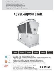
Fan heater <strong>SWS</strong>Mounting and connectionMountingThe fan heaters can be permanently mounted on awall for horizontal air distribution, or on the ceiling forvertical air distribution. The accessories are assembledwith screws or guides and then fitted to the wall orceiling with suitable fasteners. Mounting brackets areextra.Connection of heating coilBy turning the fan heater, pipe connections are possibleon both sides. Heating coil with copper pipes. Smoothpipe connections for soldering or compression fittings.A vent valve should be connected at a high point inthe pipe system. Vent- and draining valves are notincluded in the heating coil. For correct inlet and outletconnection of the heating coil, see dimension sketch.Units that are likely to be exposed to air temperaturesbelow zero, for example when a mixing cabinet is used,should be equipped with external frost protection toensure that the heating coil is not damaged by frost.ConnectionThe fan motor on 230V~ units, is connected to adetached terminal box, which is mounted on wall nextto the unit (1 m cable). The fan motor on 400V3~unitsis connected to a terminal box which is positioned onthe motor. When a mixing cabinet or a filter section isused, holes must be made in the casing for connectioncables.Accessories<strong>SWS</strong>T, drip trayUsed to collect condensation when the unit is used forcooling.For information about other accessories, see fan heaterSWH.Type Description32SWB0SWB1SWB2SWB3SWF1SWF2SWF3SWD1SWD2SWD3SWEF1SWEF2SWEF3SWFTN02SWFTN1SWFTN2SWFTN3SWBS1SWBS2SWBS3SWY1SWY2SWY3SWLR1SWLR2SWLR3<strong>SWS</strong>T02<strong>SWS</strong>T1<strong>SWS</strong>T2<strong>SWS</strong>T3Mounting brackets <strong>SWS</strong>02Mounting brackets <strong>SWS</strong>12Mounting brackets <strong>SWS</strong>22Mounting brackets <strong>SWS</strong>32/<strong>SWS</strong>33Filter section <strong>SWS</strong>12Filter section <strong>SWS</strong>22Filter section <strong>SWS</strong>32/<strong>SWS</strong>33Return air intake <strong>SWS</strong>12Return air intake <strong>SWS</strong>22Return air intake <strong>SWS</strong>32/<strong>SWS</strong>33Extra filter cassette EU3 <strong>SWS</strong>12Extra filter cassette EU3 <strong>SWS</strong>22Extra filter cassette EU3 <strong>SWS</strong>32/<strong>SWS</strong>33Basic filter <strong>SWS</strong>02Basic filter <strong>SWS</strong>12Basic filter <strong>SWS</strong>22Basic filter <strong>SWS</strong>32/<strong>SWS</strong>33Mixing cabinet <strong>SWS</strong>12Mixing cabinet <strong>SWS</strong>22Mixing cabinet <strong>SWS</strong>32/<strong>SWS</strong>33Outer wall grille <strong>SWS</strong>12Outer wall grille <strong>SWS</strong>22Outer wall grille <strong>SWS</strong>32/<strong>SWS</strong>33Extra air director <strong>SWS</strong>12Extra air director <strong>SWS</strong>22Extra air director <strong>SWS</strong>32/<strong>SWS</strong>33Drip tray <strong>SWS</strong>02Drip tray <strong>SWS</strong>12Drip tray <strong>SWS</strong>22Drip tray <strong>SWS</strong>32/<strong>SWS</strong>33181) Fan heater <strong>SWS</strong>2) Mounting brackets SWB3) Basic filter SWFTN4) Filter section SWF64595) Return air intake SWD6) Mixing cabinet SWBS7) Outer wall grille SWY8) Extra air director SWLR9) Drip tray <strong>SWS</strong>T7
Fan heater <strong>SWS</strong>Control options<strong>SWS</strong> 230V~Control by thermostat onlyThe thermostat starts/stops the fan and also controls theheat supply on/off. The fan is set to run on high speed.Complete regulation kit:• KRT1900 or T10/TK10, room thermostat• TVV20/25, 2-way valve or TRV20/25 3-way valve +SD20, acutator5-step control of airflow onlyThe air flow is manually regulated in 5 steps. No heatregulation, maximum water flow through the heatingcoil.Complete regulation kit:• RE1,5, 5-step regulator max 1,5A, orRE3, 5-step regulator max 3A, orRE7, 5-step regulator max 7AThermostat and 5-step controlThe thermostat starts/stops the fan and also controls theheat supply on/off. The air flow is manually regulated in5 steps.Complete regulation kit:• RE1,5, 5-step regulator max 1,5A, orRE3, 5-step regulator max 3A, orRE7, 5-step regulator max 7A• KRT1900 or T10/TK10, room thermostat• TVV20/25, 2-way valve or TRV20/25 3-way valve +SD20, actuator<strong>SWS</strong> 400V3~2-step control of airflow onlyThe air flow is manually regulated in 2 steps. No heatregulation, maximum water flow through the heatingcoil.Complete regulation kit:• SWYD1, 2-step change-over switch for air flow (Y/D)• STDT16, thermal contact motor protectionThermostat and 2-step controlThe thermostat controls the heat supply on/off. The airflow is manually regulated in 2 steps.Complete regulation kit:• KRT1900 or T10/TK10, room thermostat• SWYD1, 2-step change-over switch for air flow(Y/D)• STDT16, thermal contact motor protection• TVV20/25, 2-way valve or TRV20/25 3-way valve +SD20, actuatorFor further options, see section on thermostats andcontrols or contact Frico.
Fan heater <strong>SWS</strong>Output charts waterIncoming / outgoing water temperature 90/70 °CAir temp. in = -15 °C Air temp. in = 0 °C Air temp. in = +15 °CType FanpositionAirflow Output Airtemp.outWaterflowPressure OutputdropAirtemp.outWaterflowPressure OutputdropAirtemp.outWaterflowPressuredrop[m³/h] [kW] [°C] [l/s] [kPa] [kW] [°C] [l/s] [kPa] [kW] [°C] [l/s] [kPa]<strong>SWS</strong>02 max 1260 23,4 34 0,29 23,0 19,0 42 0,23 15,7 14,8 49 0,18 10,0min (80V) 520 12,7 49 0,05 7,6 10,3 55 0,13 5,1 7,9 60 0,10 3,2<strong>SWS</strong>12 max 2340 35,8 25 0,44 16,1 29,0 34 0,36 11,0 22,5 43 0,28 6,9min (80V) 620 15,0 48 0,18 3,3 12,0 54 0,15 2,2 9,3 59 0,11 1,4<strong>SWS</strong>22 max 3560 57, 4 27 0,70 21,0 46,6 36 0,57 14,3 36,3 45 0,44 9,1min (80V) 860 22,0 52 0,27 3,6 17,7 57 0,22 2,4 13,7 61 0,17 1,5<strong>SWS</strong>32 max 6300 95,4 25 1,17 33,3 77,5 34 0,95 22,7 60,5 43 0,74 14,4min (80V) 1540 37,8 49 0,46 6,1 30,4 55 0,37 4,1 23,5 60 0,29 2,5<strong>SWS</strong>33 max 6090 125,0 39 1,53 59,7 101,0 46 1,24 40,5 78,9 53 0,97 25,6min (80V) 1550 45,9 63 0,56 9,5 36,80 66 0,45 6,3 28,4 68 0,35 3,9<strong>SWS</strong>323 max ∆ 5890 92,2 26 1,14 30,8 75,00 35 0,93 21,1 58,6 44 0,73 13,3min Y 4400 77,5 31 0,96 22,3 62,80 39 0,78 15,2 49,0 47 0,61 9,6<strong>SWS</strong>333 max ∆ 5660 120,0 40 1,48 54,2 97,00 47 1,20 36,8 75,5 54 0,94 23,2min Y 4300 99,6 45 1,23 38,7 80,50 52 1,00 26,1 62,6 57 0,78 16,4Incoming / outgoing water temperature 80/60 °CAir temp. in = -15 °C Air temp. in = 0 °C Air temp. in = +15 °CType FanpositionAirflow Output Airtemp.outWaterflowPressure OutputdropAirtemp.outWaterflowPressure OutputdropAirtemp.outWaterflowPressuredrop[m³/h] [kW] [°C] [l/s] [kPa] [kW] [°C] [l/s] [kPa] [kW] [°C] [l/s] [kPa]<strong>SWS</strong>02 max 1260 20,7 28 0,25 18,7 16,3 36 0,20 12,2 12,2 43 0,15 6,5min (80V) 520 11,3 42 0,14 6,2 8,8 47 0,11 4,0 6,6 52 0,08 2,4<strong>SWS</strong>12 max 2340 31,4 20 0,38 13,0 24,8 29 0,30 8,4 18,5 38 0,22 4,9min (80V) 620 13,2 41 0,16 2,6 10,3 46 0,13 1,7 7,6 51 0,09 1,0<strong>SWS</strong>22 max 3560 50,6 22 0,62 16,9 40,0 31 0,49 11,0 29,9 39 0,36 6,5min (80V) 860 19,4 44 2,37 2,9 15,2 49 0,19 1,9 11,3 53 0,14 1,1<strong>SWS</strong>32 max 6300 84,0 20 1,02 26,8 66,5 29 0,81 17,4 49,8 38 0,61 10,2min (80V) 1540 33,4 42 0,41 4,9 26,2 47 0,32 3,1 19,5 52 2,37 1,8<strong>SWS</strong>33 max 6090 110,0 32 1,34 48,4 87,2 40 1,06 31,3 65,3 46 0,79 18,4min (80V) 1550 40,7 54 0,50 7,7 31,8 57 0,39 4,9 23,7 60 0,29 2,9<strong>SWS</strong>323 max ∆ 5890 80,8 21 0,98 25,0 64,0 30 0,78 16,2 47,9 39 0,58 9,5min Y 4400 67,9 25 0,83 18,1 53,6 34 0,65 11,7 40,1 42 0,49 6,9<strong>SWS</strong>333 max ∆ 5660 105,0 34 1,28 44,4 83,1 41 1,01 28,7 62,2 47 0,76 16,8min Y 4300 87,7 38 1,07 31,7 69,1 44 0,84 20,4 51,6 50 0,63 11,9
25203015105Fan heater <strong>SWS</strong>Wiring diagrams<strong>SWS</strong> 230V~Internal wiring diagramM ~L NYellow-GreenBrownBlackBlueL N1 2230 V~Control by thermostat onlyT10,electronicthermostatSD20TVV20/25T10/TK10A/B<strong>SWS</strong><strong>SWS</strong>LLNN1 21 2SD20,actuatorTK10,electronicthermostat withknob>t°C762244L N230 V~TVV20/25,two way valveTRV20/25,three way valveSD20<strong>SWS</strong>LN1 2SD20,actuatorKRT1900,capillary tube thermostatTVV20/25123<strong>SWS</strong>LN 1 2TVV20/25,two way valveKRTL N230 V~TRV20/25,three way valve
Fan heater <strong>SWS</strong>Wiring diagrams<strong>SWS</strong> 400V3~Internal wiring diagram<strong>SWS</strong>323/333∆ 400V3~<strong>SWS</strong>323/333Y 400V3~M ~M ~BlackOrangeBrownRedBlueGreyBlackOrangeBrownRedBlueGreyU1V2 V1 W2 W1 U2TK TKU1V2 V1 W2 W1 U2 TK TKL1L2L3400 V3~L1 L2 L3400 V3~2-step control of airflow only<strong>SWS</strong>323/333M ~Full speedBlackOrangeBrownGreyRedBlueTK TKU1V2V1 U2W2 W1Half speedSTDT16TKTKL3L2L1531642SWYD11 2 3 4 5 6 7 8 9 10 11 12 13 14 15 16 17 18 19 20
25203015105Fan heater <strong>SWS</strong>Wiring diagrams<strong>SWS</strong> 400V3~Thermostat and 2-step controlSD20T10,electronic thermostatTVV20/25T10/TK10A/B<strong>SWS</strong>323/333TK10,electronic thermostatwith knob>t°C762244BlackOrangeM ~BrownGreyRedBlueFull speedL N230 V~STDT16TKTK TK U1V2V1 U2W2 W1Half speedTKSD20,actuator400 3V~L3L2L1531642SWYD11 2 3 4 5 6 7 8 9 10 11 12 13 14 15 16 17 18 19 20TVV20/25,two way valveTRV20/25,three way valveSD20TVV20/25<strong>SWS</strong>323/333M ~KRT1900,capillary tubethermostatKRT321BlackTK TK U1OrangeV2BrownGreyV1 U2RedBlueW2 W1Full speedHalf speedL N230 V~STDT16TKTKSD20,actuator400 3V~L3L2L1531642SWYD11 2 3 4 5 6 7 8 9 10 11 12 13 14 15 16 17 18 19 20TVV20/25,two way valveTRV20/25,three way valveFrico AB031 336 86 00www.frico.se