CVM-12 - Thermon Manufacturing Company
CVM-12 - Thermon Manufacturing Company
CVM-12 - Thermon Manufacturing Company

You also want an ePaper? Increase the reach of your titles
YUMPU automatically turns print PDFs into web optimized ePapers that Google loves.
<strong>CVM</strong>-<strong>12</strong>Heat TracingMonitoring ModuleOperating GuideSWM-020.2
<strong>CVM</strong>-<strong>12</strong>Heat Tracing Monitoring ModuleIndexIntroduction .................................................................................. 4Specifications ........................................................................ 5Certifications/Approvals ....................................................... 5Nominal Dimensions ............................................................. 6Accessories ........................................................................... 6Typical Wiring Schematicfor Voltage Monitoring ........................................................... 7Operating the <strong>CVM</strong>-<strong>12</strong> in VoltageMonitoring Service ................................................................. 8Typical Wiring Schematicfor Current Loss Monitoring ...................................................... 11Operating the <strong>CVM</strong>-<strong>12</strong> in CurrentMonitoring Service ...................................................................... <strong>12</strong>Data Highway Communications .................................................. 15Other Features ............................................................................... 17Typical Application Configurations for the <strong>CVM</strong>-<strong>12</strong> ................. 21Help ................................................................................................ 243
<strong>CVM</strong>-<strong>12</strong> Heat Tracing Monitoring ModuleINTRODUCTION . . .The <strong>CVM</strong>-<strong>12</strong> is a twelve circuit microprocessor-based module designed specifically forcost effective multi-point heat tracing monitoring. The <strong>CVM</strong>-<strong>12</strong> can monitor for loss ofvoltage at either the circuit breaker or at the end of a heat tracing circuit through a thirdwire continuity monitor. As an alternate to voltage monitoring for constant wattage(parallel, series, and power limiting) type heat tracing circuits, the <strong>CVM</strong>-<strong>12</strong> monitoringmodule (when equipped with current sensing transformers) can also be configured todetect current loss in each heat tracing circuit.The <strong>CVM</strong>-<strong>12</strong> is especially well suited for use in ambient sensed power distributionpanels controlling large numbers of freeze protection heat tracing circuits.4
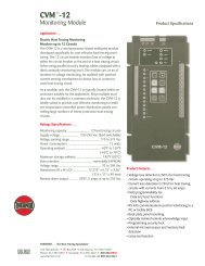
Operating GuideSPECFICATIONS . . .The <strong>CVM</strong>-<strong>12</strong> heat tracing monitor has the following specifications:Module Supply Voltage:Voltage Sensing:Power Consumption:Module Operating Ambient:Maximum Storage Ambient:Data Retention:Current Sensors:Alarm Relay Output:<strong>12</strong>0/240 Vac (field switchable)110 Vac to 575 Vac<strong>12</strong> watts per module-40°F to 158°F (-40°C to 70°C)185°F (85°C)Non-volatile EEPROMCT-60 (up to twelve)Single pole, double throw rated at 5A at 240 VacCERTIFICATIONS/APPROVALS . . .The <strong>CVM</strong>-<strong>12</strong> heat tracing monitor has the following certifications/approvals:Canadian Standards AssociationFor Use in Ordinary LocationsUnderwriters Laboratories, Inc.For Use in General Purpose Industrial Control PanelsFor Use in Control Panels (Type Z) inHazardous (Classified) LocationsClass 1, Division 2, Groups A, B, C and D5
<strong>CVM</strong>-<strong>12</strong> Heat Tracing Monitoring ModuleNOMINAL DIMENSIONS . . .The <strong>CVM</strong>-<strong>12</strong> heat tracing monitor has the following overall dimensions:ACCESSORIES . . .The <strong>CVM</strong>-<strong>12</strong> can be equipped wtih up to twelve CT-60 current sensors (see below)when utilizing the current loss monitoring feature of this module.6
Operating GuideTYPICAL WIRING SCHEMATIC FOR VOLTAGE MONITORING . . .The <strong>CVM</strong>-<strong>12</strong> may be used to detect the loss of voltage for up to twelve circuit breakersor at the ends of up to twelve heat tracing circuits.7
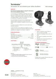
<strong>CVM</strong>-<strong>12</strong> Heat Tracing Monitoring ModuleOPERATING THE <strong>CVM</strong>-<strong>12</strong> IN VOLTAGE MONITORING SERVICE . . .The <strong>CVM</strong>-<strong>12</strong> can scan for the loss of voltage at either the circuit breaker or at the end ofthe third wire monitor lead (continuity monitoring) through the twelve voltage senseleads connected on the terminal strip at the right hand side of the module.READING THE INITIAL VOLTAGE LEVELWhen the <strong>CVM</strong>-<strong>12</strong> has been installed, the heat tracing installation has been completedand the system is energized, it is necessary to read the normal operating voltage foreach circuit into the <strong>CVM</strong>-<strong>12</strong> memory. To read data:1) Press the "PROG" key.2) Press the "DATA" key. Note that the "PROG" LED, as well as the "DATA" LED,will illuminate denoting operation in the programming mode and that a circuitnumber illuminates. If instead, the <strong>CVM</strong>-<strong>12</strong> reverts back to the "SCAN" mode asindicated by an illuminated "SCAN" LED and "LOCK" LED, the <strong>CVM</strong>-<strong>12</strong> is in asecure mode which prevents programming. Proceed to page 16 for proceduresnecessary to unlock the controller.3) Press the "UP ARROW" key to scroll through the circuit numbers.4) Press the "ENTER" key to select the desired circuit for which the normal operatingvoltage is to be read.13248
Operating Guide5) If it is desired to read all the operating voltages at once, press the "UP ARROW" keyuntil all the circuit LED's illuminate. Then press the "ENTER" key. The <strong>CVM</strong>-<strong>12</strong> willthen automatically read the circuit's voltages when the "HEAT" LED is illuminated(contactor sense HO input is energized). The <strong>CVM</strong>-<strong>12</strong> will verify which circuitsare wired for voltage monitoring (voltage is present at voltage sense input). Thenormal voltage level for each energized circuit will subsequently be read intomemory.6) The <strong>CVM</strong>-<strong>12</strong> should complete the voltage data acquisition in3 minutes or less. Todetermine the status of the "DATA" acquisition, press the "DATA" read key while the"DATA" LED is illuminated. This will result in the <strong>CVM</strong>-<strong>12</strong> illuminating the circuitnumbers which have yet to be completed. Upon completion of the voltage "DATA"acquisition for all circuits, the "DATA" LED will turn off. Once the "DATA" LED turnsoff, a press of the "DATA" key will result in the illumination of any circuit numberswhich have been determined by the <strong>CVM</strong>-<strong>12</strong> to not be in use. Warning ... thesecircuits will not alarm.7) To secure the normal circuit voltage readings, press the "PROG" key. The "PROG"LED will illuminate. Sequentially, press the "LOCK" key and the "ENTER" key to lockthe normal readings into memory. The "LOCK" LED will now illuminate and a specialkeying sequence will be required for any later re-read of normal voltage levels.75679
<strong>CVM</strong>-<strong>12</strong> Heat Tracing Monitoring ModuleREADING THE INITIAL VOLTAGE LEVELWhen the <strong>CVM</strong>-<strong>12</strong> has been installed, the heat tracing installation has been completedand the system is energized, it is necessary to read the normal operating voltage foreach circuit into the <strong>CVM</strong>-<strong>12</strong> memory. To read data:1) Press the "PROG" key.2) Press the "DATA" key. Note that the "PROG" LED, as well as the "DATA" LED,will illuminate denoting operation in the programming mode and that a circuitnumber illuminates. If instead, the <strong>CVM</strong>-<strong>12</strong> reverts back to the "SCAN" mode asindicated by an illuminated "SCAN" LED and "LOCK" LED, the <strong>CVM</strong>-<strong>12</strong> will verifythat each circuit is wired for voltage monitoring (voltage is present on each circuitinput). The normal voltage level for each enabled circuit will subsequently beread into memory.3) Press the "UP ARROW" key to scroll through the circuit numbers.4) Press the "ENTER" key to select the desired circuit for which the normal operatingvoltage is to be read.2110
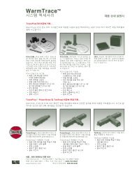
Operating GuideTYPICAL WIRING SCHEMATIC FOR CURRENT LOSS MONITORING . . .When equipped with CT-60 current sensors, the <strong>CVM</strong>-<strong>12</strong> may be used to detect a 25%loss of current in a heat tracing circuit. The typical wiring schematic for this is as shownbelow.SEETABLE ATABLE AOperating Circuit AmperageRangeNumber of Wire Passes ThroughCurrent Transformer.5A to .999A81.0A to 1.999A 42.0A to 3.999A24.0A to 60AStraight Thru11
<strong>CVM</strong>-<strong>12</strong> Heat Tracing Monitoring ModuleOPERATING THE <strong>CVM</strong>-<strong>12</strong> IN CURRENT MONITORING SERVICE . . .The <strong>CVM</strong>-<strong>12</strong> can scan for a loss of heat tracing current of 25% or more through thetwelve current sensors connected on the terminal strip at the left hand side of themodule.READING THE INITIAL CURRENT LEVELWhen the <strong>CVM</strong>-<strong>12</strong> has been installed, the heat tracing installation has been completedand the system is energized, it is necessary to read the normal operating current foreach circuit into the <strong>CVM</strong>-<strong>12</strong> memory. To read data:1) Press the "PROG" key.2) Press the "DATA" key. Note that the "PROG" LED, as well as the "DATA" LED,will illuminate denoting operation in the programming mode and that a circuitnumber illuminates. If instead, the <strong>CVM</strong>-<strong>12</strong> reverts back to the "SCAN" mode asindicated by an illuminated "SCAN" LED and "LOCK" LED, the <strong>CVM</strong>-<strong>12</strong> is in asecure mode which prevents programming. Proceed to page 16 for proceduresnecessary to unlock the controller.3) Press the "UP ARROW" key to scroll through the circuit numbers.4) Press the "ENTER" key to select the desired circuit for which the normal operatingcurrent is to be read.1324<strong>12</strong>
Operating Guide5) If it is desired to read all the operating currents at once, press the "UP ARROW" keyuntil all the circuit LED's illuminate. Then press the "ENTER" key. The <strong>CVM</strong>-<strong>12</strong> willthen automatically read the circuit's current when the "HEAT" LED is illuminated(contactor sense H0 input is energized). The <strong>CVM</strong>-<strong>12</strong> will verify which circuits arewired for current monitoring (current is sensed at the CT-60 current transformerswhich are connected to the <strong>CVM</strong>-<strong>12</strong>). The normal current level for each enabledcircuit will subsequently be read into memory.6) The <strong>CVM</strong>-<strong>12</strong> should complete the current data acquisition in 20 minutes or less. Todetermine the status of the "DATA" acquisition, press the "DATA" read key while the"DATA" LED is illuminated. This will result in the <strong>CVM</strong>-<strong>12</strong> illuminating the circuitnumbers which have yet to be completed. Upon completion of the current "DATA"acquisition for all the circuits, the "DATA" LED will turn off. Once the "DATA" LEDturns off, a press of the "DATA" key will result in the illumination of any circuitnumbers which have been determined by the <strong>CVM</strong>-<strong>12</strong> to not be in use. Warning ...these circuits will not alarm. If a circuit is known to be active and yet the circuitnumber LED illuminates when the "DATA" key is pressed, it is possible that the totalcurrent read within the CT-60 is less than 4 Amperes. If so, refer to Page 11 Table Afor the number of loops through the CT-60 and adjust the wiring for this circuit.7) To secure the normal circuit current readings, press the "PROG" key. The "PROG"LED will illuminate. Sequentially, press the "LOCK" key and the "ENTER" key to lockthe normal readings into memory. The "LOCK" LED will now illuminate and a specialkeying sequence will be required for any later re-read of normal current levels.756713
<strong>CVM</strong>-<strong>12</strong> Heat Tracing Monitoring ModuleTHE <strong>CVM</strong>-<strong>12</strong> IN SCAN MODEOnce the initial current "data read" is complete, the <strong>CVM</strong>-<strong>12</strong> will begin to continuallyscan each of the twelve heat tracing circuits and will alarm should the current drop bymore than 25%. If an alarm condition does occur, the common alarm relay will activate(open or close depending on wiring configuration). In addition, the alarm will appear asa flashing circuit number to the left of the keypad.1) Press the "ALARM ACK" key to acknowledge all circuit numbers which are in alarm.Once the "ALARM ACK" key is pressed, the circuit number(s) which are in alarm willstop flashing but will remain illuminated until the circuit current once again exceeds75% of the normal value. In addition, the common alarm action clears and thecontacts will be reset.2) Pressing the "DATA" key when in Scan mode will result in the illumination of anycircuit numbers which have been determined by the <strong>CVM</strong>-<strong>12</strong> to be in use. Thesecircuits will not alarm.2114
Operating GuideDATA HIGHWAY COMMUNICATIONS . . .When the <strong>CVM</strong>-<strong>12</strong> is connected into an RS 485 two wire twisted pair data highway,alarm events can be sent back to the facility DCS or to a PC which has been set up withTraceView Plus communications software. Through its ModBus communicationsprotocol, the <strong>CVM</strong>-<strong>12</strong> will report to the PC or to the DCS the following information:1) the circuit number in alarm2) the <strong>CVM</strong>-<strong>12</strong> data highway address3) the alarm status (alarm, alarm acknowledged, or alarm cleared)15
<strong>CVM</strong>-<strong>12</strong> Heat Tracing Monitoring ModuleREADING AND PROGRAMMING THE DATA HIGHWAY ADDRESS1) The data highway address may be checked when in the scan mode by simplypressing the "DATA HWY" key. The left "HWY" LED will first illuminate and anumber LED will illuminate to the left of the keypad. This number indicates the"tens place" digit of the data highway address.2) Pressing the "DATA HWY" key again illuminates the right "HWY" LED signifying the"ones place" digit in the data highway address. For example, the successiveillumination of a four and a five will indicate that this <strong>CVM</strong>-<strong>12</strong> is set as the datahighway address 45.3) To re-program the data highway address (the <strong>CVM</strong>-<strong>12</strong> must be in an un-locked 1condition to do this), press the "PROG" key.4) Then press the "DATA HWY" key. The "PROG" LED will illuminate indicating thatyou are in the programming mode of operation. Subsequently, the left "HWY" LEDwill illuminate and the current "tens place" digit will illuminate.5) Press the "UP ARROW" key to scroll to a new numeric value.6) Press the "ENTER" key to select the new value.7) Press the "DATA HWY" key again and the "ones place" digit will illuminate.8) Again press the "UP ARROW" key to scroll to a new value.9) Press the "ENTER" key to select the new value.1Refer to page 16 for the "Unlock" procedure.335, 821, 2,4, 7456, 916
Operating GuideOTHER FEATURES . . .The <strong>CVM</strong>-<strong>12</strong> has several other features which may be found useful.LAMP TEST1) Pressing the "LAMP TEST" key will result in all LED's in the <strong>CVM</strong>-<strong>12</strong> illuminating.This provides reassurance to the user that the <strong>CVM</strong>-<strong>12</strong> is ready and able toproperly report all information and alarm events.117
<strong>CVM</strong>-<strong>12</strong> Heat Tracing Monitoring ModuleUNLOCKING THE CONTROLLER SETTINGSIf at some point in the life of the heat tracing system a modification is required whichmay alter the normal operating voltage or current on a particular circuit, or if a new datahighway address is desired, it is possible to unlock the initially programmed values andread in the new data.1) Press the "PROG" and "LOCK" key sequentially.2) Press the "UP ARROW" key until the circuit number LED corresponding to thedesired "tens place" of the data highway address illuminates.Tens PlaceOnes Place3) Press "ENTER".4) Press the "UP ARROW" key until the circuit number LED corresponding to thedesired "one's place" of the data highway address illuminates.5) Press "ENTER" again and the "LOCK" LED will turn off indicating that any or allcircuit normal operating values may be re-set.Proceed with re-programming as previously described.2, 43, 5118
Operating GuideSCAN LEDThe <strong>CVM</strong>-<strong>12</strong> is provided with a "SCAN" LED. This LED illuminates when the <strong>CVM</strong>-<strong>12</strong> isoperating in the SCAN mode of operating and monitoring each heat tracing circuit.HEAT LEDThe <strong>CVM</strong>-<strong>12</strong> is provided with a "HEAT" LED. This LED illuminates when the contactorsense voltage is detected (power is being supplied to the heat tracing circuits).REMOTE PUSHBUTTON ACCESSThe <strong>CVM</strong>-<strong>12</strong> may be wired to external panel mounted pushbuttons to both acknowledgealarms and also to do a lamp test without the need to open the panel.19
<strong>CVM</strong>-<strong>12</strong> Heat Tracing Monitoring ModuleVOLTAGE SELECTION SWITCHThe <strong>CVM</strong>-<strong>12</strong> may be switched from 240 Vac (the factory setting) to <strong>12</strong>0 Vac by pressingthe rocker switch on the right side of the module. Note that this rocker switch alsocontains a 1 Amp fast blow type fuse.MIXED MODE MONITORINGThe <strong>CVM</strong>-<strong>12</strong> may be operated with some of the twelve circuits within a module beingset up for current loss monitoring and the remaining circuits set up for voltage lossmonitoring. The <strong>CVM</strong>-<strong>12</strong> automatically checks for the presence of a current sensor andthus is able to detect the exact equipment configuration. It is, however, not possible todo both current loss and voltage loss monitoring on the same circuit.20
<strong>CVM</strong>-<strong>12</strong> Heat Tracing Monitoring ModuleHELP . . .The <strong>CVM</strong>-<strong>12</strong> is intended to be used with only the support of this instruction booklet. Ifspecial support needs do arise, <strong>Thermon</strong> provides local support through its arearepresentatives and affiliate companies as well as through a toll free user support line.For toll free support, dial 1-800-820-HEAT (4328).24
Operating GuideNOTES . . .25
<strong>CVM</strong>-<strong>12</strong> Heat Tracing Monitoring ModuleNOTES . . .26
Operating GuideNOTES . . .27
THERMON. . . The Heat Tracing Specialists ®100 <strong>Thermon</strong> Dr. • P.O. Box 609 • San Marcos, TX 78667-0609 •Phone: (5<strong>12</strong>) 396-5801• Facsimile: (5<strong>12</strong>) 396-3627 • 1-800-820-HEAThttp://www.thermon.com Part Number: 50307