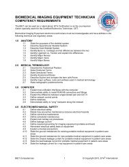
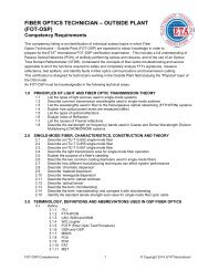
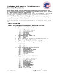
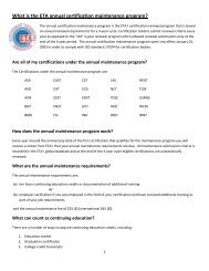
Understanding Op-Ampby Karl Eilers, CATCircuitry – Part 2First a correction: in part 1, figure1, the labels on the inputs are reversed.Here is that figure again,with correct labels. Apologies to anyonewho was confused by this.We concluded the discussion in part 1 with the basic differential-input amplifier,figure 2. This is a very commonly used circuit, but it has a couple ofdrawbacks. First, it is impossible to achieve high gain, high input impedance,high precision and low noise. As shown in the earlier article, to havea high gain the ratio of R3 to R1 must be high. This either means R1 mustbe small, resulting in alow input impedance, orR3 must be very large,resulting in noise. Also,if the op-amp uses bipolartransistors, the DCoffset error will be large.(This is discussed inmore detail below.)Second, the resistances of the signal effectively become part of R1 and R2.For example, if R1=10K and RS1 (source resistance 1) = 1K, that effectivelymeans R1=11K. If accurate measurement is important, this is a problem,because it changes the gain of the circuit. Also, if RS1 is not equal to RS2,this upsets the balancing and ruins the common-mode rejection. RS1 notequal to RS2 is a common occurrence in instrumentation, where a balancedcircuit is often used to measure the voltage of an unbalanced source. In thatcase, one of the inputs would be tied to the source’s ground, so either RS1or RS2 would be zero.filters, but op-amp based filters are often better. These are called “activefilters” because they require a DC power source and use amplifying components.In the circuit in figure 4A, gain rises withfrequency. If we first consider the casewhere RS=0, that is, a piece of wire, wewill have a differentiator, whose outputis proportional to the change in inputvoltage over a period of time:Eq. 2 Vo = - Rf C (dVi / dt)WhereVo = output voltageRf = feedback resistor in ohmsC = input capacitor in faradsdVi / dt = change in input voltage per secondNote the negative sign; this circuit gives a negative output for a rising inputsignal.One problem with this design is that the capacitor reactance and thus inputimpedance varies inversely with frequency. Thus the impedance of the signalsource must be low enough so this variation does not affect the results.Also, the output voltage of the differentiator rises with frequency, theoreticallyto infinity, making the circuit susceptible to high frequency noise.We can’t actually build a true differentiator. A circuit whose gain rises withno limit will be too quirky to use in thereal world. In practical circuits, a gainlimit is set by adding RS in series withthe capacitor. At some high frequency,where the reactance of the capacitorequals RS, the slope of the line changesfrom rising to flat, as shown in figure 4B.This is called the “corner” frequency.Eq. 3 Fc = 1 / 2RsCwhere R is in ohms and C in farads. Replace 1 with 10^6 to work in microfaradsand 10^12 to work in picofarads.These problem can be overcome with the circuit of figure 3, the InstrumentationAmplifier (IA). R5 must equal R6 and R8 should equal R9. AssumingR1 = R2 = R3 = R4, the voltage gain is:Eq. 1 Gv = 1 + 2(R5 / R7)R5, 6 and 7 can be low resistance, solving noise and offset problems. Gainis set by a single resistor, R7, and can be made adjustable. If we use FETinputop-amps, input impedance is set by R8 and R9, which are only thereto keep the input voltages from drifting when the IA is not connected toanything. These can be very high-resistance, resulting in an amplifier withhigh impedance inputs on both sides and making source resistance issuesirrelevant.Filters, Differentiators, IntegratorsIn the preceding circuits, all frequencies are treated equally within the opamp’soperating band. But by adding capacitors, op-amps can make excellentfilters too. Inductors, capacitors and resistors alone can make goodAbove the corner frequency, the circuit approximates a conventional invertingamplifier with gain = Rf / Rs.This circuit can also be used to discriminate against low frequencies. Whenused this way, it is called a “high pass filter.” A better name would be a “lowattenuate filter,” because its function is to attenuate frequencies below Fc.For example, in mobile communication radios, the lower range of the humanvoice occupies more modulation than it’s worth. It is customary to pass theaudio signal through a high pass filter to reserve more modulation for thevoice’s higher harmonics, which actually carry information.Whether this circuit is a differentiator or a high pass filter depends on howwe think of it, and what it is designed to do.In the circuit of figure 5A, which is the mirror-image of the one of figure 4A,output falls with frequency. If we first consider the case where RF is an opencircuit, we will have an integrator. With a changing input voltage, the differentiatorshows us its rate of change at a given instant while the integrator8 | The <strong>High</strong>-<strong>Tech</strong> News | JAN/FEB2010
shows us its average over time:Eq. 4 dVout / dt = -Vin / RCwheredVout = change in output voltagedt = change in time in secondsMathematically, this is a bit complex, involvingdifferential calculus, but conceptually it’s simple. Think of a tank withwater in it. The water level depends on how fast water is flowing in or out,and how long that’s been going on. The water level corresponds to theoutput voltage.Again, a circuit without RF, a true integrator, isn’t practical. C is an opencircuit at DC, meaning there’s no DC feedback path to set the quiescent or“resting” output voltage, which will drift uncontrolled. With RF, there will bea corner frequency found by:Eq. 5 Fc = 1 / 2RfCBelow this frequency, the circuit approximatesa normal inverting amp. If its purpose is toattenuate high frequencies, it is called a lowpassfilter. The response curve is shown infigure 5B.DC Output Voltage ErrorsUp to this point, we have been ignoring the fact that real-world op-amps arenot perfect. In reality, the quiescent DC output voltage is never exactly whatit is supposed to be. There are three principal causes of this:• Input bias current• Input current offset• Input voltage offsetIn many circuits, this is of no importance. If we’re amplifying and processinghigh-frequency signals, there will be series capacitors in the circuit and DCoffsets will not be coupled from one part of the circuit to another. But inmeasurement and control applications, starting with the right DC voltage isoften critical. The problem is made worse by the fact that offset current andvoltage drift with time and changes in temperature.Let’s look at bias current first. Inmost op-amps, the inputs are internallyconnected to the bases of twobipolar junction transistors. BJTs requirea small amount of base currentto operate. This shows up as currentflowing out of the input connections(or into them, depending on the BJTs’ polarity) and through the associatedcircuitry. This is shown in figure 6A, which is a standard inverting amplifier.Note that the “+” input is connected to ground, while the “-“ input is connectedto two resistors. This means the voltage at “+” will be zero, while thevoltage at “-“ will not, because there will be voltage drop across the resistors.There is a voltage difference between the inputs, which will show up at theoutput magnified by the circuit’s gain.Figure 6B shows the most common wayto fix this. R3, inserted between the “+”input and ground, should have a resistanceequal to the parallel resistance ofR1 and R2. To be really accurate, theresistance of the signal source should befigured into the value of R1. This waythe voltage drop between the outputs and ground will be equal.We’re still not out of the woods. One of the virtues of the integrated circuitop-amp is that input voltage and current are automatically well matched –but they’re not perfectly matched. The input current imbalance, or offset,will cause differing voltage drops across the associated resistors. This problemand the previous one can be eliminated by using FET-input op-amps.The input current of a FET is essentially zero.We still have the input voltage offset to deal with. The easiest fix, though itwill only get us close, is to pay extra for factory-trimmed or selected op-amps.The second is to deliberately inject a tiny correction voltage into one of theinputs. This is drawn from the power supply, cut down by a voltage divider,and adjusted by a pot.The third is to buy an op-amp with extra terminals for connection to anoffset-trimming pot.The fourth and most complicated is to use a chopper-stabilized amplifier,which chops up the DC signal into AC, amplifies it, then integrates it back toa DC signal. This method has the advantage of automatically correcting fordrift, which is why choppers are often called zero-drift amplifiers.Gain, Frequency Response and StabilityAs stated in part 1, the DC gain of an op-amp is very high. However, there isalways some high frequency at which the phase shift of the op-amp becomesgreat enough to cause oscillation. If the op-amp is going to be usable as avoltage follower, with a circuit gain of unity, then its own gain must fall belowunity by the time it reaches that critical frequency.Figure 7 shows the gain-vs.-frequency behavior of the 741 op-amp. Its opencircuit gain is around 200,000, but already at 5Hz the gain is beginning tofall. It reaches unity gain at 1MHz.The usable frequency range in a circuitdepends on how much gain you’re goingfor. With a 741, if you want a voltagegain of 10,000, you’re only going to getit to 100Hz, because that’s all the gain a741 has at that frequency. On the otherhand, if you’re only going for 100X gain,the 741 is good to 10kHz. This is aconsideration that affects most op-ampcircuit designs.Op-amps are now available that will work into the hundreds of MHz. On theother hand, if we don’t need fast response, we can choose an op-amp that’smuch slower than a 741 and uses a tiny fraction of the power. In an applicationlike remote, solar-powered telemetry, this would extend battery life.Sine-Wave OscillatorsOp-amps have dozens of other uses; we’ll just mention this one. Feedback tothe “-“ input stabilizes the circuit. This kind of feedback is called “negativefeedback,” because it reduces gain. It also reduces error, which is to say ithas a stabilizing influence.Feedback to the “+” is called “positive feedback.” Any output voltagechange is further increased by positive feedback. In other words, positivefeedback has a destabilizing influence. The whole reason op-amp stability isan issue, as discussed above, is that phase shift can turn negative feedbackinto positive feedback at some frequencies.But in an oscillator, we don’t want stability. We want the circuit to go into aself-sustaining, oscillating mode, producing a continuous output waveform.On the other hand, we want a well-controlled waveform at a defined frequency.The easiest way to do that is to combine positive and negative feedback.The circuit in figure 8 is a form of sine-waveoscillator. The feedback circuit connectedto the “-“ input is a frequency-selectivenetwork. This particular arrangement iscalled a “Wein bridge.” The circuit connectedto the “+” input is a variable feedbacknetwork that gets things oscillating.Once an oscillator starts, it will run awaywith itself unless there’s some automatic stabilization network. This simpleone uses the variable resistance of an incandescent lamp. Nowadays, a FETwith a lot of circuitry attached is likely to take the place of the lamp.A lot more could be written about op-amps. If you have specific questions,forward them to <strong>ETA</strong>-I, and another article might result, either in HTN oronline. HTNJAN/FEB2010 | etainternational.org | 9