Diagnostic Flowcharts
Diagnostic Flowcharts
Diagnostic Flowcharts

You also want an ePaper? Increase the reach of your titles
YUMPU automatically turns print PDFs into web optimized ePapers that Google loves.
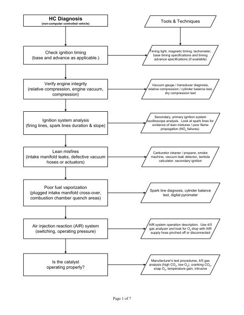
HC Diagnosis(non-computer controlled vehicle)Tools & TechniquesCheck ignition timing(base and advance as applicable.)Timing light, magnetic timing, tachometer,base timing specifications and timingadvance specifications (if available)Verify engine integrity(relative compression, engine vacuum,compression)Vacuum gauge / transducer diagnosis,relative compression / cylinder balance test,dry compression testIgnition system analysis(firing lines, spark lines duration & slope)Secondary, primary ignition systemoscilloscope analysis. Look at spark lines forevidence of lean mixtures / poor flamepropogation (NO xfailures).Lean misfires(intake manifold leaks, defective vacuumhoses or actuators)Carburetor cleaner / propane, smokemachine, vacuum leak detector, lambdacalculator, secondary ignitionPoor fuel vaporization(plugged intake manifold cross-over,combustion chamber quench areas)Spark line diagnosis, cylinder balancetest, digital pyrometerAir injection reaction (AIR) system(switching, operating pressure)AIR system operation description. Use 4/5gas analyzer and look for O 2drop with AIRsupply hose pinched off or disconnectedIs the catalystoperating properly?Manufacturer's test procedures, 4/5 gasanalysis (high CO 2, low O 2), cranking CO 2,snap O 2, temperature gain, intrusivePage 1 of 7
HC Diagnosis(computer controlled vehicle)Tools & TechniquesRefer to "High HC Non-feedback"diagnostic flowchartTiming; mechanical, electrical lean air/fuel misfires, vaporization, AIR, catalystDTC's?Scan tool, jumper wire,screwdriver,DTC pulling instructionisYesNoDiscern between hard and soft codesPull codes, record codes in the orderthey are displayed, erase codes,operate vehicle, pull hard codesFollow manufacturer's or publisheddiagnostic / repair procedures forhard codesScan tool, multimeter, DSO, DTCdiagnostic flowcharts, diagnostic &repair informationTest O 2S with DSOPropane enrichment tool, DSOminimum voltage = 0 - 175mVmaximum = 800 - 1000mVrate of change = < 100 mS (175mV - 800 mV)O 2S in goodseviceable condition?NoUpon repair of O 2S circuit orreplacement of sensor, re-test O 2SYesMap O 2S signal with DSOHigh frequency signal = misfireSignal biased below 450 mV = lean mixtureSignal biased above 450 mV = rich mixturePage 2 of 7
CO Diagnosis(non-computer controlled vehicle)Tools & TechniquesCheck air intake system forrestrictionsPlugged / dirty air filter, improper chokeoperation, plugged PCV system, improper TACoperationCheck for unmetered fuel enteringthe engineImproper EVAP purge operation, saturated EVAPcannister, fuel contaminated engine oil (> 500 ppmHC after 5 minutes measured at the oil filler neckengine off)Check carburetor operationFloat level, choke operation, mainmetering, power valve, idle circuitCheck air injection systemoperationUse system description / operation to verify properswitching. Check operating pressure by pinching offsupply hose and verifying O 2drop in tailpipe emissionsCheck catalyst(s) operationAfter upstream repairs are complete, use manufacturer'sprocedures to test efficiency. Combinations of cranking CO 2,snap O 2, HC efficiency, temperature gain are useful whenmanufacturer's procedures aren't available.Page 3 of 7
CO Diagnosis(computer controlled vehicle)Tools &TechniquesRefer to "High CO Non-Feedback"diagnostic flowchartAir intake restriction,unmetered fuel,carburetor, air injection,catalyst operationDTC's?Scan tool, jumper wire,screwdriver, DTC pullinginstructionsYesNoDiscern between hard and soft codesPull codes, record codes in theorder they are displayed, erasecodes, operate vehicle, pull hardcodes (OBD I)Follow manufacturer's or publisheddiagnostic / repair procedures for hardcodesScan tool, multimeter,DCO, DTC diagnosticflowcharts, diagnostic &repair informationReview data stream (if available) orconfirm related sensor/outputperformance. Test O 2S with DSO.DMM, DSO, propaneenrichment tool,break-out boxCheck for vehicle computer operation (isthe fuel metering system capable of beingartificially driven rich or lean, is the timingbeing controlled? Perform manufacturer'srecommended system performance check)4/5 gas analyzer,timing light, sensorsimulatorPage 4 of 7
NO xDiagnosisTools &TechniquesCheck ignition timing(base and advance as applicable.)Timing light, magnetictiming, tachometer, basetiming specifications andtiming advancespecifications (if available)Check exhaust gas recirculation (EGR)system(if equipped)Vacuum guage/pump,tachometer, scantoolCheck for lean air/fuel mixtureLambda calculator, gasanalyzer, biased O 2Spattern, fuel trim data,secondary ignition patternCheck for excessive coolant and/orintake air temperaturePyrometer, scantool,temperature probe,thermometerCheck for excessive combustionchamber pressureCompression guage,borescope, TSBsCheck for proper fuel octane ratingOwner's manual,vehicle ownerCheck catalyst operation(vehicles equipped with a reduction catalyst only)Manufacturer's testprocedures, 4/5 gas analysis(high CO 2, low O 2), crankingCO 2, snap O 2, temperaturegain, intrusivePage 5 of 7
OBD II <strong>Diagnostic</strong>sTools &TechniquesMIL illuminated?MIL functional test(KOEO bulb check)YesPull DTC's and record freezeframe dataScan tool, paper & pencil. Donot erase DTC's unlessinstructed to do so by diagnostic/ repair proceduresNoFollow manufacturer's orpublished diagnostic / repairprocedures for DTC's. Beginwith the DTC refered to infreeze frame dataScan tool, multimeter, DSO,DTC diagnostic flowcharts,diagnostic & repairinformationReview pending DTC's,monitor status, mode 6 andmode 5 data, fuel trim andmisfire dataPerform a system performancecheck and/or a complete drivecycle as per manufacturer'sinstructionsScan toolManufacturer's orpublished diagnostic &repair informationCheck PCM for DTC's(pending or matured), reviewmode 6 and mode 5 data forfailed test resultsScan toolPage 6 of 7
<strong>Diagnostic</strong> PreliminariesPost-diagnosis processVehicle fails Smog CheckAnalyze diagnostic information(component test data, measurements,waveform analysis, etc.)Prepare an estimatefor diagnosisPrepare a repair strategybased on diagnosticinformationObtain customer authorizationPrepare an estimate to repairdefects relative to the failuredetermined in the diagnosisVerify customer complaint(baseline inspection in pre-inspectionmode, training mode, manual mode orpartial pre-inspection) when appropriateDiscuss the repair strategy withthe customer and obtainauthorizationSelect a method to documentdiagnosis(vehicle information datasheet, technotes, etc.)Perform authorized repairs,gauge repair effectiveness<strong>Diagnostic</strong> Assumptions• Visual inspection• TSB's and helpful hints• Engine integrity• Powers and groundsPage 7 of 7