
You also want an ePaper? Increase the reach of your titles
YUMPU automatically turns print PDFs into web optimized ePapers that Google loves.
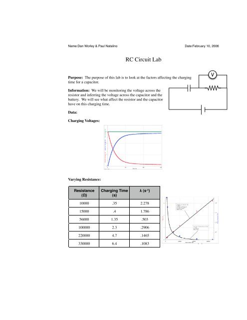
Name:Dan Worley & Paul Natalino Date:February 10, 2006<strong>RC</strong> <strong>Circuit</strong> <strong>Lab</strong>Purpose: The purpose of this lab is to look at the factors affecting the chargingtime for a capacitor.VInformation: We will be monitoring the voltage across theresistor and inferring the voltage across the capacitor and thebattery. We will see what affect the resistor and the capacitorhave on this charging time.Data:Charging Voltages:Varying Resistance:Resistance(Ω)Charging Time(s)λ (s -1 )10000 .35 2.27815000 .4 1.78656000 1.35 .503100000 2.3 .2906Time (s)220000 4.7 .1465330000 6.4 .1083 Resistance (!)
Name:Dan Worley & Paul Natalino Date:February 10, 2006Varying Capacitance:Capacitance(µF)Charging Time(s)λ (s -1 )10 .8 .902833 2.35 .2939Time (s)220 16 .04397Capacitance (µF)Conclusion:The purpose of this lab is to look at the factors affecting the charging time for a capacitor. In thislab, there were three parts. The first part involved finding the voltages at two different places inthe circuit, the resistor and the capacitor. We also added the voltage of the resistor and the voltageof the capacitor to find the total voltage that remained constant. We did this by hooking upour circuit with the voltmeter and a 1 MΩ resistor in parallel and a capacitor in series after theparallel. Another explanation of the circuit was the resistor and capacitor are hooked up in series,with a branch coming across the resistor, making the resistor be in parallel with the voltmeter.The second part involved finding how the timing constant and decay constant change as youchange the resistance. We did this by switching out resistors for each trial. We then used the examinefeature on Logger Pro to figure out the timing constant. We used the graph type, naturalexponent to determine the C value, which is the decay constant. We used the same setup as inthe previous part, the only thing that changed was the resistor each time. The third part involvedchanging capacitors.For the first part, we found that total voltage remained constant, the voltage of the capacitor increasedquickly in the beginning but leveled off, asymptotically approaching the voltage of thebattery. The resistor voltage decreased rapidly in the beginning, leveling off, asymptotically approaching0. By analyzing the graph, the point where the two voltages hit is midway from theoriginal voltage is called the timing constant. The timing constant is the point on the graph orinstant in time in which the capacitor reaches half charge. The resistor graph was a natural exponentwith an A value of 5.921, B value of .3104, and a C value of .05473. The equation forfinding these constants is V=Vo*e^-Ct. The second part showed that time increased linearlywith a slope of 0.1925 e-5 as the resistance increased. The decay constant decreased as resistanceincreased in an inverse fashion. We had an A value of 2.416 X 10 -4 . In the third part, ourresults were the same as the second part, the time increased in a linear fashion with a slope of.7262 and the inverse decay constant had an A value of 9.006. From the entire lab, we learnedthat battery voltage remains constant, capacitor never fully charges to the battery voltage. Thehigher the resistance and capacitance, the longer that it took for the capacitor to reach full charge.Some possible sources of error in this lab could have been incorrect setup, incorrect reading ofresistor, and not using the trigger for data collection or not letting off ground at correct time. In
Name:Dan Worley & Paul Natalino Date:February 10, 2006order to fix the setup, you should make sure that the resistor and volt meter are in parallel, with acapacitor in series, hooked up to a battery. You should also double check the reading of the resistorto make sure that you are graphing the correct resistance. Also, you have to remember thatthere is a five to ten percent error in resistance. Finally, you should use the trigger on logger proto make sure that you start collecting data as soon as the capacitor starts to charge. You also needto remember to ground the circuit every trial.