

CONTROLLING CAVITATION: - PRO-QUIP
CONTROLLING CAVITATION: - PRO-QUIP
CONTROLLING CAVITATION: - PRO-QUIP

Create successful ePaper yourself
Turn your PDF publications into a flip-book with our unique Google optimized e-Paper software.
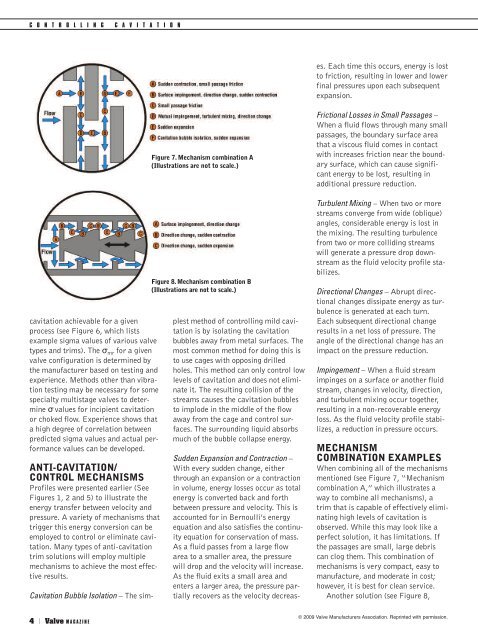
C O N T R O L L I N G C A V I T A T I O NSudden Expansion and Contraction –With every sudden change, eitherthrough an expansion or a contractionin volume, energy losses occur as totalenergy is converted back and forthbetween pressure and velocity. This isaccounted for in Bernoulli’s energyequation and also satisfies the continuityequation for conservation of mass.As a fluid passes from a large flowarea to a smaller area, the pressurewill drop and the velocity will increase.As the fluid exits a small area andenters a larger area, the pressure partiallyrecovers as the velocity decreases.Each time this occurs, energy is lostto friction, resulting in lower and lowerfinal pressures upon each subsequentexpansion.cavitation achievable for a givenprocess (see Figure 6, which listsexample sigma values of various valvetypes and trims). The σ mr for a givenvalve configuration is determined bythe manufacturer based on testing andexperience. Methods other than vibrationtesting may be necessary for somespecialty multistage valves to determineσ values for incipient cavitationor choked flow. Experience shows thata high degree of correlation betweenpredicted sigma values and actual performancevalues can be developed.ANTI-<strong>CAVITATION</strong>/CONTROL MECHANISMSProfiles were presented earlier (SeeFigures 1, 2 and 5) to illustrate theenergy transfer between velocity andpressure. A variety of mechanisms thattrigger this energy conversion can beemployed to control or eliminate cavitation.Many types of anti-cavitationtrim solutions will employ multiplemechanisms to achieve the most effectiveresults.Figure 7. Mechanism combination A(Illustrations are not to scale.)Figure 8. Mechanism combination B(Illustrations are not to scale.)Cavitation Bubble Isolation – The simplestmethod of controlling mild cavitationis by isolating the cavitationbubbles away from metal surfaces. Themost common method for doing this isto use cages with opposing drilledholes. This method can only control lowlevels of cavitation and does not eliminateit. The resulting collision of thestreams causes the cavitation bubblesto implode in the middle of the flowaway from the cage and control surfaces.The surrounding liquid absorbsmuch of the bubble collapse energy.Frictional Losses in Small Passages –When a fluid flows through many smallpassages, the boundary surface areathat a viscous fluid comes in contactwith increases friction near the boundarysurface, which can cause significantenergy to be lost, resulting inadditional pressure reduction.Turbulent Mixing – When two or morestreams converge from wide (oblique)angles, considerable energy is lost inthe mixing. The resulting turbulencefrom two or more colliding streamswill generate a pressure drop downstreamas the fluid velocity profile stabilizes.Directional Changes – Abrupt directionalchanges dissipate energy as turbulenceis generated at each turn.Each subsequent directional changeresults in a net loss of pressure. Theangle of the directional change has animpact on the pressure reduction.Impingement – When a fluid streamimpinges on a surface or another fluidstream, changes in velocity, direction,and turbulent mixing occur together,resulting in a non-recoverable energyloss. As the fluid velocity profile stabilizes,a reduction in pressure occurs.MECHANISMCOMBINATION EXAMPLESWhen combining all of the mechanismsmentioned (see Figure 7, “Mechanismcombination A,” which illustrates away to combine all mechanisms),atrim that is capable of effectively eliminatinghigh levels of cavitation isobserved. While this may look like aperfect solution, it has limitations. Ifthe passages are small, large debriscan clog them. This combination ofmechanisms is very compact, easy tomanufacture, and moderate in cost;however, it is best for clean service.Another solution (see Figure 8,4 | Valve M A G A Z I N E© 2009 Valve Manufacturers Association. Reprinted with permission.


