HX8347 - Adafruit
HX8347 - Adafruit
HX8347 - Adafruit
You also want an ePaper? Increase the reach of your titles
YUMPU automatically turns print PDFs into web optimized ePapers that Google loves.
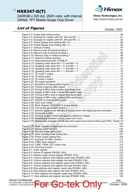
<strong>HX8347</strong>-G(T)240RGB x 320 dot, 262K color, with internalGRAM, TFT Mobile Single Chip DriverList of Figures October, 2009Himax ConfidentialFigure 5.2: Image data writing control............................................................................................... 58Figure 5.3: Example for rotation with MY, MX and MV - 1................................................................ 61Figure 5.4: Example for rotation with MY, MX and MV - 2................................................................ 62Figure 5.5: Partial Display Area Setting (ML=’0’) .............................................................................. 66Figure 5.6: Partial Display Area Setting (ML=’1’) .............................................................................. 66Figure 5.7: Vertical scrolling .............................................................................................................. 67Figure 5.8: Memory map of vertical scrolling 1 ................................................................................. 67Figure 5.9: Memory map of vertical scrolling 2 ................................................................................. 68Figure 5.10: Memory map of vertical scrolling 3 ............................................................................... 68Figure 5.11: Vertical scrolling example.............................................................................................. 69Figure 5.12: Data streaming order in RGB I/F .................................................................................. 70Figure 5.13: Updating order when MY = ‘0’ and MX = ‘0’ ................................................................. 71Figure 5.14: Updating order when MY = ‘0’ and MX = ‘1’ ................................................................. 71Figure 5.15: Updating order when MY = ‘1’ and MX = ‘0’ ................................................................. 72Figure 5.16: Updating order when MY = ‘1’ and MX = ‘1’ ................................................................. 72Figure 5.17: TE mode 1 output ......................................................................................................... 73Figure 5.18: TE delay output............................................................................................................. 73Figure 5.19: TE mode 2 output ......................................................................................................... 74Figure 5.20: TE output waveform...................................................................................................... 74Figure 5.21: Waveform of tearing effect signal ................................................................................. 75Figure 5.22: Timing of tearing effect signal....................................................................................... 75Figure 5.23: Timing of MPU write is faster than panel read.............................................................. 76Figure 5.24: Display of MPU write is faster than panel read............................................................. 76Figure 5.25: Timing of MPU write is slower than panel read............................................................. 77Figure 5.26: Display of MPU write is slower than panel read ........................................................... 77Figure 5.27: <strong>HX8347</strong>-G internal clock circuit .................................................................................... 78Figure 5.28: Gate scan mode............................................................................................................ 79Figure 5.29: Block diagram of <strong>HX8347</strong>-G power circuit.................................................................... 80Figure 5.30: LCD power generation scheme .................................................................................... 82Figure 5.31: Gamma adjustments different of source driver with digital gamma correction............. 83Figure 5.32: Grayscale control .......................................................................................................... 84Figure 5.33: Gamma resister stream and gamma reference voltage ............................................... 86Figure 5.34: Relationship between source output and Vcom ......................................................... 103Figure 5.35: Relationship between GRAM data and output level (normal white panel REV_Panel=“0”)................................................................................................................................................. 103Figure 5.36: Block diagram of digital gamma correction................................................................. 104Figure 5.37: Display on/off set flow ................................................................................................. 105Figure 5.38: Standby mode setting flow.......................................................................................... 106Figure 5.39: Deep standby mode setting flow................................................................................. 107Figure 5.40: Power supply setting flow ........................................................................................... 108Figure 5.41: Example of CABC function ..........................................................................................113Figure 5.42: CABC block diagram....................................................................................................113Figure 5.43: CABC_PWM_OUT output duty....................................................................................115Figure 5.44: Dimming function .........................................................................................................116Figure 6.1: Index register ................................................................................................................ 123Figure 6.2: Himax ID register (PAGE0 -00h)................................................................................... 123Figure 6.3: Display mode control register (PAGE0 -01h)................................................................ 123Figure 6.4: Column address start register upper byte (PAGE0 -02h)............................................. 124Figure 6.5: Column address start register low byte (PAGE0 -03h)................................................. 124Figure 6.6: Column address end register upper byte (PAGE0 -04h).............................................. 125Figure 6.7: Column address end register low byte (PAGE0 -05h).................................................. 125Figure 6.8: Row address start register upper byte (PAGE0 -06h) .................................................. 125Figure 6.9: Row address start register low byte (PAGE0 -07h)...................................................... 125Figure 6.10: Row address end register upper byte (PAGE0 -08h) ................................................. 125Figure 6.11: Row address end register low byte (PAGE0 -09h) ..................................................... 125For Go-tek OnlyThis information contained herein is the exclusive property of Himax and shall not be distributed, reproduced, or disclosedin whole or in part without prior written permission of Himax.-P.6-October, 2009


