en.2.1.123 M/160340/M/12 p1-3 - NOR-Service Kft
en.2.1.123 M/160340/M/12 p1-3 - NOR-Service Kft
en.2.1.123 M/160340/M/12 p1-3 - NOR-Service Kft

Create successful ePaper yourself
Turn your PDF publications into a flip-book with our unique Google optimized e-Paper software.
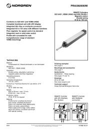
M/<strong>160340</strong>/M/<strong>12</strong>Parallel grippersDouble actingMagnetic pistonØ 10 to 25 mmIdeal for general purpose gripping applicationsSmooth, accurate movementLong, uninterrupted service lifeLow weightCompact sizeIntegral magnets for positional feedbackTechnical dataMedium:Compressed air, filtered, lubricated or non-lubricatedOperation:Double acting, parallel, magnetic pistonOperating pressure:1 to 7 bar(Ø 10 mm 1,8 to 7 bar, Ø 16 mm 1,2 to 7 bar)Operating temperature:0°C to +60°C* Air supply must be dry enough to avoid ice formation at temperatures below +2°CMounting:Mounting holes on three facesGripping repeatability:+/- 0,01 mmMechanical life:~ 5 million cycles before maintenance may be necessaryMaterialsBody: aluminium alloyTop plate: carbon steelFingers: carbon steelExternal screws: carbon steelElastomers: nitrileOrdering informationTo order a gripper with an effective closing gripforce of up to 25,5N at 5 bar quote:M/160344/M/<strong>12</strong>Order magnetically operated switchesseparatelyAccessoriesSwitch M/344 28/02Our policy is one of continued research and development. We therefore reserve the right to amend, without notice, the specifications given in this document.N/UK 2.1.<strong>12</strong>3.01For your local Norgren Technical Sales Centre phone 0345 662266. For your local Norgren Distributor phone 0345 227777.IMI Norgren Limited, PO Box 22, Eastern Avenue, Lichfield, Staffordshire WS13 6SB
M/<strong>160340</strong>/M/<strong>12</strong>Standard models • Effective gripping force • Air consumptionModelEffective gripping force (N) at 5 bar* Air consumption (cm 3 )Opening Closingat 5 bar**M/160343/M/<strong>12</strong> 14,6 9,4 0,3M/160344/M/<strong>12</strong> 34,0 25,5 1,5M/160345/M/<strong>12</strong> 60,9 45,7 3,3M/160346/M/<strong>12</strong> 87 67 6,4* Grip point L = 30 mm** per cycleTheoretical closing gripping forcesM/160343/M/<strong>12</strong>M/160344/M/<strong>12</strong>M/160345/M/<strong>12</strong>154080Gripping force (N)1057 bar5 bar3 barGripping force (N)3020207 bar5 bar3 barGripping force (N)6040207 bar5 bar3 bar010 20 30 40 50Grip point L (mm)010 20 30 40 50Grip point L (mm)010 20 30 40 50 60Grip point L (mm)<strong>12</strong>0M/160346/M/<strong>12</strong>Workpiece grip pointL1007 barGripping force (N)8060405 bar3 barH20010 20 30 40 50 60Grip point L (mm)Effective closing gripping forces = Theoretical closing gripping force x 0,85Grip point limitation rangeOverhang (H)40302010M/160343/M/<strong>12</strong> M/160344/M/<strong>12</strong> M/160345/M/<strong>12</strong>2 bar3 bar4 bar5 bar6 bar7 barOverhang (H)403020104 bar5 bar7 bar6 bar2 bar3 barOverhang (H)50403020102 bar3 bar4 bar5 bar6 bar7 bar010 20 30 40 50Grip point L (mm)010 20 30 40 50 60Grip point L (mm)020 40 60 80Grip point L (mm)Overhang (H)6050403020100M/160346/M/<strong>12</strong>3 bar4 bar5 bar6 bar7 bar2 bar20 40 60 80 100Grip point L (mm)Criteria of workpiece weightWhen chucking a workpiece, weight should be within the range between1/10 and 1/20 of the above gripping force.When chucking and then moving a workpiece, the workpiece may protrudeor drop. Therefore, workpiece weight should be less than the above mentioned value.(Reference value is 1/30-1/50)Weight depends on the operational condition, such as material and shapeof workpiece or claw, speed and direction of moving workpiece (straight advance, rotation or swing, etc.)Switches with LED indicationModel2-wire solid state3-wire solid stateVoltage V d.c. Current max.Temperature°CCable lengthStraight cableconnectionM/344/EAU/1APV 10 ... 28 20 mA 0° ... +60° ¬ - 1 m PVC – ¬M/344/EAU/1PV 10 ... 28 20 mA 0° ... +60° ¬ - 1 m PVC ¬ –M/344/EAU/3APV 10 ... 28 20 mA 0° ... +60° ¬ - 3 m PVC – ¬M/344/EAU/3PV 10 ... 28 20 mA 0° ... +60° ¬ - 3 m PVC ¬ –M/344/EAN/1APV 4,5 ... 28 50 mA 0° ... +60° ¬ NPN 1 m PVC – ¬M/344/EAN/1PV 4,5 ... 28 50 mA 0° ... +60° ¬ NPN 1 m PVC ¬ –M/344/EAN/3APV 4,5 ... 28 50 mA 0° ... +60° ¬ NPN 3 m PVC – ¬M/344/EAN/3PV 4,5 ... 28 50 mA 0° ... +60° ¬ NPN 3 m PVC ¬ –LEDFeaturesCable type90˚ elbow cableconnectionN/UK 2.1.<strong>12</strong>3.02Our policy is one of continued research and development. We therefore reserve the rightto amend, without notice, the specifications given in this document.8/02
MEG DAA AAAKSVAALHIM/<strong>160340</strong>/M/<strong>12</strong>DimensionsOPQRBBABAACFOAAUWT* Port sizeCØ A B C D E F G H I KM/160343/M/<strong>12</strong> 10 17 + 1,6 / -0,2 (open) 13 ± 0,4 (closed) 4,5 25 max 16,5 59,5 5,5 - 0,03 43 15 6 3M/160344/M/<strong>12</strong> 16 26 + 2,3 (open) 18 + 0,6 / -0,2 (closed) 6,5 37,5 max 19 71 7 - 0,03 52 17,5 8 3M/160345/M/<strong>12</strong> 20 36 + 1,5 / -0,9 (open) 24 + 0,1 / -0,9 (closed) 8,5 49 max 23 83,5 8 - 0,04 60,5 20 10 4M/160346/M/<strong>12</strong> 25 42 + 1,0 / -0,7 (open) 28 ± 0,4 (closed) 10 57,5 max 27 95 10 - 0,03 68 23 <strong>12</strong> 5Ø L M O P Q R S T U VM/160343/M/<strong>12</strong> 10 20 23 17 Ø 11 + 0,05 deep 1,5 16 10 7,5 10 10 16M/160344/M/<strong>12</strong> 16 23 34 26 Ø 17 + 0,05 deep 1,5 22 14 7,5 <strong>12</strong> 14 18M/160345/M/<strong>12</strong> 20 26 45 35 Ø 21 + 0,05 deep 1,5 26 16 8 13 16 19M/160346/M/<strong>12</strong> 25 30 52 40 Ø 26 + 0,05 deep 1,5 32 20 9 18 20 22Ø W AA AB AC kgM/160343/M/<strong>12</strong> 10 18 M3 x 0,5 M3 x 0,5 deep 5 M3 x 0,5 0,05M/160344/M/<strong>12</strong> 16 24 M5 x 0,8 M4 x 0,7 deep 7 M3 x 0,5 0,<strong>12</strong>M/160345/M/<strong>12</strong> 20 30 M5 x 0,8 M5 x 0,8 deep 8 M4 x 0,7 0,22M/160346/M/<strong>12</strong> 25 36 M5 x 0,8 M6 x 1,0 deep 10 M5 x 0,8 0,37WarningThese products are intended for use in industrial compressed air systems only. Do not use these products where pressures and temperatures canexceed those listed under ‘Technical Data’.Before using these products with fluids other than those specified, for non-industrial applications, life-support systems, or other applications notwithin published specifications, consult <strong>NOR</strong>GREN.Through misuse, age, or malfunction, components used in fluid power systems can fail in various modes.The system designer is warned to consider the failure modes of all component parts used in fluid power systems and to provide adequatesafeguards to prevent personal injury or damage to equipment in the event of such failure.System designers must provide a warning to end users in the system instructional manual if protection against a failure mode cannot beadequately provided.System designers and end users are cautioned to review specific warnings found in instruction sheets packed and shipped with these products.Our policy is one of continued research and development. We therefore reserve the right8/02 N/UK 2.1.<strong>12</strong>3.03to amend, without notice, the specifications given in this document.
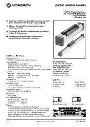
M/160350/M/<strong>12</strong>Parallel grippers - precisionDouble actingMagnetic pistonØ 8 to 50 mmIdeal for applications demanding accuracy andprecise repeatabilitySmooth, accurate movementLong, uninterrupted service lifeLow weightCompact sizeIntegral magnets for positional feedbackTechnical dataMedium:Compressed air, filtered, lubricated or non-lubricatedOperation:Double acting, parallel, magnetic pistonOperating pressure:7 bar maximum - see page 2 for minimum operating pressuresOperating temperature:+0°C to +60°C* Air supply must be dry enough to avoid ice formation at temperatures below +2°CMounting:Mounting holes on three facesGripping repeatability:+/- 0,01 mmAccuracy to centre:+/- 0,07 mmMechanical life:~ 5 million cycles before maintenance may be necessaryOperating frequency:<strong>12</strong>0 cycles per minute maximumMaterialsBody: aluminium alloyFingers: stainless steelGuide rail: stainless steelElastomers: nitrileOrdering informationTo order a gripper with an effective closing gripforce of up to 26N at 5 bar quote:M/160356/M/<strong>12</strong>Order magnetically operated switchesseparatelyAccessoriesSee pageSwitch M/344 38/02Our policy is one of continued research and development. We therefore reserve the right to amend, without notice, the specifications given in this document.N/UK 2.1.143.01For your local Norgren Technical Sales Centre phone 0345 662266. For your local Norgren Distributor phone 0345 227777.IMI Norgren Limited, PO Box 22, Eastern Avenue, Lichfield, Staffordshire WS13 6SB
M/160350/M/<strong>12</strong>Standard models • Effective gripping force • Minimum operating pressure • Air consumptionModelEffective gripping force (N) at 5 bar*Opening ClosingMinimum operatingpressure in barM/160354/M/<strong>12</strong> 9,9 5,8 2,2 0,15M/160355/M/<strong>12</strong> 15 9,4 2,0 0,41M/160356/M/<strong>12</strong> 39 26 1,2 1,6M/160357/M/<strong>12</strong> 60 45 1,0 3,7M/160358/M/<strong>12</strong> 176 157 1,0 16,4M/160359/M/<strong>12</strong> 414 347 1,0 61,0* Grip point L = 30 mm** per cycleAir consumption (cm 3 )at 5 bar**Workpiece grip pointHLTheoretical closing gripping forces10M/160354/M/<strong>12</strong>15M/160355/M/<strong>12</strong>40M/160356/M/<strong>12</strong>Gripping force (N)57 bar5 bar3 barGripping force (N)1057 bar5 bar3 barGripping force (N)3020107 bar5 bar3 bar010 20 30 40020 40 60 70020 40 60 80 100Grip point L (mm)Grip point L (mm)Grip point L (mm)Gripping force (N)80604020M/160357/M/<strong>12</strong>7 bar5 bar3 barGripping force (N)25020015010050M/160358/M/<strong>12</strong>7 bar5 bar3 barGripping force (N)500400300200100M/160359/M/<strong>12</strong>7 bar5 bar3 bar030 60 90 <strong>12</strong>0050 100 150050 100 150Grip point L (mm)Grip point L (mm)Grip point L (mm)Effective closing gripping forces = Theoretical closing gripping force x 0,85Grip point limitation rangeM/160354/M/<strong>12</strong>M/160355/M/<strong>12</strong>M/160356/M/<strong>12</strong>4040Overhang (H)3020103 bar4 bar5 bar6 bar7 barOverhang (H)3020102 bar3 bar4 bar5 bar6 bar7 barOverhang (H)50403020102 bar3 bar4 bar5 bar6 bar7 bar010 20 30 40020 40 60 80020 40 60 80 100Grip point L (mm)Grip point L (mm)Grip point L (mm)M/160357/M/<strong>12</strong>M/160358/M/<strong>12</strong>M/160359/M/<strong>12</strong>Overhang (H)6040202 bar3 bar4 bar5 bar6 bar7 barOverhang (H)150130100502 bar3 bar4 bar5 bar6 bar7 barOverhang (H)150130100502 bar3 bar4 bar5 bar6 bar7 bar030 60 90 <strong>12</strong>0050 100 150050 100 150Grip point L (mm)Grip point L (mm)Grip point L (mm)N/UK 2.1.143.02Our policy is one of continued research and development. We therefore reserve the rightto amend, without notice, the specifications given in this document.8/02
M/160350/M/<strong>12</strong>Switches with LED indicationModel2-wire solid state3-wire solid stateVoltage V d.c. Current max.Temperature°CCable lengthStraight cableconnectionM/344/EAU/1APV 10 ... 28 20 mA 0° ... +60° ¬ - 1 m PVC – ¬M/344/EAU/1PV 10 ... 28 20 mA 0° ... +60° ¬ - 1 m PVC ¬ –M/344/EAU/3APV 10 ... 28 20 mA 0° ... +60° ¬ - 3 m PVC – ¬M/344/EAU/3PV 10 ... 28 20 mA 0° ... +60° ¬ - 3 m PVC ¬ –M/344/EAN/1APV 4,5 ... 28 50 mA 0° ... +60° ¬ NPN 1 m PVC – ¬M/344/EAN/1PV 4,5 ... 28 50 mA 0° ... +60° ¬ NPN 1 m PVC ¬ –M/344/EAN/3APV 4,5 ... 28 50 mA 0° ... +60° ¬ NPN 3 m PVC – ¬M/344/EAN/3PV 4,5 ... 28 50 mA 0° ... +60° ¬ NPN 3 m PVC ¬ –LEDFeaturesCable type90˚ elbow cableconnectionDimensionsM/160354/M/<strong>12</strong>AAFB CAC BAFODEQAHAAOAAAIPADCZYXACRWGHIABKMLAGSUVT* Port sizeØ A B C D E G H I KM/160354/M/<strong>12</strong> 8 8 3 2,5 15 7 ± 0,03 9 +1,5 (open) 5 + 0,5 (closed) 20 15 Ø 9 + 0,05 deep 1Ø L M N O P Q R S T UM/160354/M/<strong>12</strong> 8 13 ± 0,05 8 - 1,2 8 1,5 Ø 1,5 - 0,03 4 1,5 28,5Ø V W X Y Z AA AB AC ADM/160354/M/<strong>12</strong> 8 9,7 <strong>12</strong> 5 ± 0,025 17 4 M3 x 0,5 M2,5 x 0,45 deep 4 Ø 1,5 + 0,02 deep 1 Ø 3,2Ø AF AG AH Al AL kgM/160354/M/<strong>12</strong> 8 M2 X 0,4 deep 3,5 10 5 15 M3 X 0,5 deep 3 0,02Our policy is one of continued research and development. We therefore reserve the right8/02 N/UK 2.1.143.03to amend, without notice, the specifications given in this document.
M/160350/M/<strong>12</strong>M/160355/M/<strong>12</strong>M/160356/M/<strong>12</strong>M/160357/M/<strong>12</strong>M/160358/M/<strong>12</strong>ABAFCCABAFPODQAAOAAAAAIAHCOAEADCVABZADSAGYUACEXRTFWGHNIABLM* Port sizeABKAKØ A B C D E F G H I KM/160355/M/<strong>12</strong> 10 14,7 5 4,5 17 <strong>12</strong> ± 0,03 20 15,5 + 1,5 (open) 9 + 0,5 (closed) 36 17 Ø 11 + 0,05 deep 1,5M/160356/M/<strong>12</strong> 16 20 8 6 24 16 ± 0,03 30 22 + 1,8 (open) <strong>12</strong> + 1,3 (closed) 50 26 Ø 17 + 0,05 deep 1,5M/160357/M/<strong>12</strong> 20 24 8 8 30 22 ± 0,03 40 30 + 2,4/-0,5 (open) 16 + 1,4 (closed) 62 35 Ø 21 + 0,05 deep 1,5M/160358/M/<strong>12</strong> 32 31 14 9,5 30 30 ± 0,03 50 41 + 1,80 (open) 19 + 1,30 (closed) 85 40 Ø 34 + 0,050 deep 2Ø L M N O P Q R S T UM/160355/M/<strong>12</strong> 10 20 ± 0,05 10 23 9 7 <strong>12</strong> Ø 3 - 0,03 <strong>12</strong>,5 1,5 47,5M/160356/M/<strong>12</strong> 16 25 ± 0,05 14 34 <strong>12</strong> 15 15 Ø 4 - 0,03 15 2 54M/160357/M/<strong>12</strong> 20 32 ± 0,05 16 45 16 17 18 Ø 5 - 0,03 20 3 64M/160358/M/<strong>12</strong> 32 40 ± 0,05 30 52 20 20 20 Ø 6 - 0,03 31 4 79Ø V W X Y Z AA AB AC AD AEM/160355/M/<strong>12</strong> 10 11 17 7 ± 0,025 29 6 M3 x 0,5 M3 x 0,5 deep 4,5 Ø 2,5 + 0,02 deep 2,5 M4 x 0,7 deep 6 Ø 3,4M/160356/M/<strong>12</strong> 16 14 20 9 ± 0,025 36 8 M5 x 0,8 M4 x 0,7 deep 5 Ø 3 + 0,02 deep 3 M4 x 0,7 deep 6 Ø 3,4M/160357/M/<strong>12</strong> 20 17 27 <strong>12</strong> ± 0,025 43 8 M5 x 0,8 M4 x 0,7 deep 7 Ø 4 + 0,02 deep 3,5 M5 x 0,8 deep 8 Ø 4,2M/160358/M/<strong>12</strong> 32 20 32 15 ± 0,025 53 13 M5 x 0,8 M8 x 1 deep 9 Ø 5 + 0,03 deep 4 M6 x 1 deep 9 Ø 5,2Ø AF AG AH AI AK AL AM AN AO kgM/160355/M/<strong>12</strong> 10 M3 x 0,5 deep 4 24 7,5 17 30 M3 x 0,5 deep 5 M3 x 0,5 deep 6 16 M3 x 0,5 deep 5 0,08M/160356/M/<strong>12</strong> 16 M4 x 0,7 deep 5 31 7,5 19 42 M4 x 0,7 deep 6 M4 x 0,7 deep 7 21 M3 x 0,5 deep 5 0,16M/160357/M/<strong>12</strong> 20 M5 x 0,8 deep 7 37 7,5 21 54 M5 x 0,8 deep 8 M5 x 0,8 deep 9 27,3 M4 x 0,7 deep 6 0,33M/160358/M/<strong>12</strong> 32 M6 x 1 deep 9 46 9 28,5 70 M6 x 1 deep 8 M6 x 1 deep 9 31 M5 x 0,8 deep 8 0,66N/UK 2.1.143.04Our policy is one of continued research and development. We therefore reserve the rightto amend, without notice, the specifications given in this document.8/02
M/160350/M/<strong>12</strong>M/160359/M/<strong>12</strong>BAFBCCAAODAHPAAAFOAICUZACAGTSXRFEGAMWAKIABLMQADVAAAEYAKADAC* Port sizeKNHØ A B C D E F G H I KM/160359/M/<strong>12</strong> 50 41 24 20,5 50 58 ± 0,03 75 77 + 1,8/-0,2 (open) 41 + 0,4 (closed) 119 60 Ø 52 + 0,05 deep 3Ø L M N O P Q R S T UM/160359/M/<strong>12</strong> 50 60 ± 0,05 45 75 40 42 30 Ø 8 - 0,02 55 7,5 110Ø V W X Y Z AA AB AC AD AEM/160359/M/<strong>12</strong> 50 33 46 20 -0,025 70 20 Rc1/8 M6 X 1 deep <strong>12</strong> Ø 6 + 0,03 deep 7 M8 x 1,25 deep <strong>12</strong> Ø 11 deep 6,5Ø AF AG AH Al AK AL AM AN AO AP kgM/160359/M/<strong>12</strong> 50 M6 x 1 deep <strong>12</strong> 60 11 38 105 M8 x 1,25 deep <strong>12</strong> 4 45 M5 x 0,8 deep 8 M8 x 1,25 deep 15 1,85WarningThese products are intended for use in industrial compressed air systems only. Do not use these products where pressures and temperatures canexceed those listed under ‘Technical Data’.Before using these products with fluids other than those specified, for non-industrial applications, life-support systems, or other applications notwithin published specifications, consult <strong>NOR</strong>GREN.Through misuse, age, or malfunction, components used in fluid power systems can fail in various modes.The system designer is warned to consider the failure modes of all component parts used in fluid power systems and to provide adequatesafeguards to prevent personal injury or damage to equipment in the event of such failure.System designers must provide a warning to end users in the system instructional manual if protection against a failure mode cannot beadequately provided.System designers and end users are cautioned to review specific warnings found in instruction sheets packed and shipped with these products.Our policy is one of continued research and development. We therefore reserve the right8/02 N/UK 2.1.143.05to amend, without notice, the specifications given in this document.
M/160360/M/<strong>12</strong>Parallel grippers - low profileDouble actingMagnetic pistonØ 8 to <strong>12</strong> mmIdeal for applications where operating space isrestrictedSmooth, accurate movementLong, uninterrupted service lifeLow weightCompact sizeIntegral magnets for positional feedbackTechnical dataMedium:Compressed air, filtered, lubricated or non-lubricatedOperating pressure:M/160364/M/<strong>12</strong>: 2 to 7 barM/160365/M/<strong>12</strong>: 1,5 to 7 barOperating temperature:0°C to +60°C* Air supply must be dry enough to avoid ice formation at temperatures below +2°CMounting:Mounting holes on three facesGripping repeatability:+/- 0,07mmAccuracy to centre:+/- 0,1mmMaterialsBody: aluminium alloyFingers: carbon steelBearings: stainless steelElastomers: nitrileOrdering informationTo order a gripper with an effective closing gripforce of up to 16,7N at 5 bar quote:M/160364/M/<strong>12</strong>Order magnetically operated switchesseparatelyAccessoriesSee pageSwitch M/344 28/02Our policy is one of continued research and development. We therefore reserve the right to amend, without notice, the specifications given in this document.N/UK 2.1.163.01For your local Norgren Technical Sales Centre phone 0345 662266. For your local Norgren Distributor phone 0345 227777.IMI Norgren Limited, PO Box 22, Eastern Avenue, Lichfield, Staffordshire WS13 6SB
M/160360/M/<strong>12</strong>Standard models • Effective gripping force • Air consumptionModelEffective gripping force (N) at 5 bar* Air consumption (cm 3 )Opening Closingat 5 bar**M/160364/M/<strong>12</strong> 16,7 16,7 1,4M/160365/M/<strong>12</strong> 44 44 4,3* Grip point L = 30 mm** per cycleTheoretical gripping forcesM/160364/M/<strong>12</strong>M/160365/M/<strong>12</strong>Workpiece grip pointL40607 barGripping force (N)3020107 bar5 bar3 barGripping force (N)50403020105 bar3 barH010 20 30 40 50 60 70020 40 60 80Grip point L (mm)Grip point L (mm)Grip point limitation rangeM/160364/M/<strong>12</strong>M/160365/M/<strong>12</strong>4060Overhang (H)3020107 bar5 bar3 barOverhang (H)50403020103 bar5 bar7 bar010 20 30 40 50 60 70020 40 60 80Grip point L (mm)Grip point L (mm)Switches with LED indicationModel2-wire solid state3-wire solid stateVoltage V d.c. Current max.Temperature°CCable lengthStraight cableconnectionM/344/EAU/1APV 10 ... 28 20 mA 0° ... +60° ¬ - 1 m PVC – ¬M/344/EAU/1PV 10 ... 28 20 mA 0° ... +60° ¬ - 1 m PVC ¬ –M/344/EAU/3APV 10 ... 28 20 mA 0° ... +60° ¬ - 3 m PVC – ¬M/344/EAU/3PV 10 ... 28 20 mA 0° ... +60° ¬ - 3 m PVC ¬ –M/344/EAN/1APV 4,5 ... 28 50 mA 0° ... +60° ¬ NPN 1 m PVC – ¬M/344/EAN/1PV 4,5 ... 28 50 mA 0° ... +60° ¬ NPN 1 m PVC ¬ –M/344/EAN/3APV 4,5 ... 28 50 mA 0° ... +60° ¬ NPN 3 m PVC – ¬M/344/EAN/3PV 4,5 ... 28 50 mA 0° ... +60° ¬ NPN 3 m PVC ¬ –LEDFeaturesCable type90˚ elbow cableconnectionN/UK 2.1.163.02Our policy is one of continued research and development. We therefore reserve the rightto amend, without notice, the specifications given in this document.8/02
M/160360/M/<strong>12</strong>DimensionsAAADNOCPQRSTXAC*AGYAC*MOCABFGHDAFZUVWIKLAB* Port sizeAEEØ A B C D E F G H I KM/160364/M/<strong>12</strong> 8 52 32 2,5 Ø 5 8,1 13 26 32 16,2 17 +1,7/-0,5 (open) 1 +0,7/-1,0 (closed)M/160365/M/<strong>12</strong> <strong>12</strong> 66 30 3 Ø 7 11,4 15 35 41 22,8 23 +1,9/-0,5 (open) 1 +0,9/-1,0 (closed)Ø L M N O P Q R S T UM/160364/M/<strong>12</strong> 8 10 24 17 <strong>12</strong> 5 13 19 2 8,5 Ø 8 + 0,05 deep 1M/160365/M/<strong>12</strong> <strong>12</strong> <strong>12</strong> 40 20 17 7 18 25 2 11 Ø 8 + 0,05 deep 1Ø V W X Y Z AA AB AC AD AEM/160364/M/<strong>12</strong> 8 24 40 Ø 5 27 2,5 + 0,03 deep 2,5 M3 x 0,5 deep 5 M2,5 x 0,45 deep 3 M3 x 0,5 2 M3 x 0,5 deep 5M/160365/M/<strong>12</strong> <strong>12</strong> 30 50 Ø 5 36 3 + 0,03 deep 3 M4 x 0,7 deep 8 M3 x 0,5 deep 3 M5 x 0,8 2 M4 x 0,7 deep 6Ø AF AG kgM/160364/M/<strong>12</strong> 8 Ø 2,5 + 0,03 deep 2,5 M3 x 0,5 deep 5 0,09M/160365/M/<strong>12</strong> <strong>12</strong> Ø 3 + 0,03 deep 3 M3 x 0,5 deep 5 0,2WarningThese products are intended for use in industrial compressed air systems only. Do not use these products where pressures and temperatures canexceed those listed under ‘Technical Data’.Before using these products with fluids other than those specified, for non-industrial applications, life-support systems, or other applications notwithin published specifications, consult <strong>NOR</strong>GREN.Through misuse, age, or malfunction, components used in fluid power systems can fail in various modes.The system designer is warned to consider the failure modes of all component parts used in fluid power systems and to provide adequatesafeguards to prevent personal injury or damage to equipment in the event of such failure.System designers must provide a warning to end users in the system instructional manual if protection against a failure mode cannot beadequately provided.System designers and end users are cautioned to review specific warnings found in instruction sheets packed and shipped with these products.Our policy is one of continued research and development. We therefore reserve the right8/02 N/UK 2.1.163.03to amend, without notice, the specifications given in this document.
M/160380/M/<strong>12</strong>Parallel grippers - three jawDouble actingMagnetic pistonØ 16 to 20 mmIdeal for gripping spheres or components withcircular facesSmooth, accurate movementLong, uninterrupted service lifeLow weightCompact sizeintegral magnets for positional feedbackTechnical dataMedium:Compressed air, filtered, lubricated or non-lubricatedOperation:Double acting, three jaw parallel, magnetic pistonOperating pressure:2 to 7 bar1,5 to 7 bar M/160386/M/<strong>12</strong>Operating temperature:+0°C to +60°C* Air supply must be dry enough to avoid ice formation at temperatures below +2°CMounting:Mounting holes on baseGripping repeatability:+/- 0,01 mmMechanical life:~ 5 million cycles before maintenance may be necessaryOperating frequency:200 cycles per minute maximumMaterialsBody: aluminium alloyTop plate: carbon steelFingers: carbon steelExternal screws: carbon steelElastomers: nitrileOrdering informationTo order a gripper with an effective closing gripforce of up to 20N at 5 bar quote:M/160385/M/<strong>12</strong>Order magnetically operated switchesseparatelyAccessoriesSee pageSwitch M/344 28/02Our policy is one of continued research and development. We therefore reserve the right to amend, without notice, the specifications given in this document.N/UK 2.1.183.01For your local Norgren Technical Sales Centre phone 0345 662266. For your local Norgren Distributor phone 0345 227777.IMI Norgren Limited, PO Box 22, Eastern Avenue, Lichfield, Staffordshire WS13 6SB
M/160380/M/<strong>12</strong>Standard models • Effective gripping force • Air consumptionModelEffective gripping force (N) at 5 bar* Air consumption (cm 3 )Opening Closingat 5 bar**M/160385/M/<strong>12</strong> 27 20 1,4M/160386/M/<strong>12</strong> 36 27 3,3* Grip point L = 30 mm** per cycleTheoretical closing gripping forcesM/160385/M/<strong>12</strong>M/160386/M/<strong>12</strong>Workpiece grip pointL5050Gripping force (N)4030201007 bar5 bar3 bar10 20 30Grip point L (mm)40 50 60Effective closing gripping forces = Theoretical closing gripping force x 0,85Gripping force (N)40302010010 20 307 bar5 bar3 barGrip point L (mm)40 50 6 0Criteria of workpiece weightWhen chucking a workpiece, weight should be within therange between 1/10 and 1/20 of the above gripping force.When chucking and then moving a workpiece, theworkpiece may protrude or drop. Therefore, workpieceweight should be less than the above mentioned value.(Reference value is 1/30-1/50)Weight depends on the operational condition, such asmaterial and shape of workpiece or claw, speed anddirection of moving workpiece (straight advance,rotation or swing, etc.)Grip point limitation rangeM/160385/M/<strong>12</strong>M/160386/M/<strong>12</strong>7766Pressure (bar)543Pressure (bar)5432211010 20 30 40 50 60 0Grip point L (mm)10 20 30 40 50 60 70 80 90Grip point L (mm)Switches with LED indicationModel2-wire solid state3-wire solid stateVoltage V d.c. Current max.Temperature°CCable lengthStraight cableconnectionM/344/EAU/1APV 10 ... 28 20 mA 0° ... +60° ¬ - 1 m PVC – ¬M/344/EAU/1PV 10 ... 28 20 mA 0° ... +60° ¬ - 1 m PVC ¬ –M/344/EAU/3APV 10 ... 28 20 mA 0° ... +60° ¬ - 3 m PVC – ¬M/344/EAU/3PV 10 ... 28 20 mA 0° ... +60° ¬ - 3 m PVC ¬ –M/344/EAN/1APV 4,5 ... 28 50 mA 0° ... +60° ¬ NPN 1 m PVC – ¬M/344/EAN/1PV 4,5 ... 28 50 mA 0° ... +60° ¬ NPN 1 m PVC ¬ –M/344/EAN/3APV 4,5 ... 28 50 mA 0° ... +60° ¬ NPN 3 m PVC – ¬M/344/EAN/3PV 4,5 ... 28 50 mA 0° ... +60° ¬ NPN 3 m PVC ¬ –LEDFeaturesCable type90˚ elbow cableconnectionN/UK 2.1.183.02Our policy is one of continued research and development. We therefore reserve the rightto amend, without notice, the specifications given in this document.8/02
M/160380/M/<strong>12</strong>DimensionsPQ<strong>12</strong>0°GH ITKFO RDBACLM<strong>12</strong>0°* Port sizeEAA*SØ A B C D E F G H I KM/160385/M/<strong>12</strong> 16 53 23 27 2 <strong>12</strong>,5 M4 x 0,7 deep 7 10 5 2,5 24M/160386/M/<strong>12</strong> 20 61,5 30,5 28 2 13 M5 x 0,8 deep 8 <strong>12</strong>,5 7 3,0 30Ø L M O P Q R S T AA kgM/160385/M/<strong>12</strong> 16 Ø 32 Ø 42 Ø 3 - 0,005 7 - 0,03 M3 x 0,5 9,5 + 0,9/-0,4 (open) 5,5 + 0,9/-0,4 (closed) 7,5 Ø 17 + 0,05 deep 1,5 M5 x 0,8 0,16M/160386/M/<strong>12</strong> 20 Ø 38 Ø 54 Ø 3 - 0,005 8 - 0,04 M4 x 0,7 13 + 1,6/-0,4 (open) 7 + 1,2/-0,4 (closed) 8 Ø 21 + 0,05 deep 1,5 M5 x 0,8 0,28WarningThese products are intended for use in industrial compressed air systems only. Do not use these products where pressures and temperatures canexceed those listed under ‘Technical Data’.Before using these products with fluids other than those specified, for non-industrial applications, life-support systems, or other applications notwithin published specifications, consult <strong>NOR</strong>GREN.Through misuse, age, or malfunction, components used in fluid power systems can fail in various modes.The system designer is warned to consider the failure modes of all component parts used in fluid power systems and to provide adequatesafeguards to prevent personal injury or damage to equipment in the event of such failure.System designers must provide a warning to end users in the system instructional manual if protection against a failure mode cannot beadequately provided.System designers and end users are cautioned to review specific warnings found in instruction sheets packed and shipped with these products.Our policy is one of continued research and development. We therefore reserve the right8/02 N/UK 2.1.183.03to amend, without notice, the specifications given in this document.
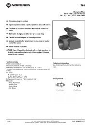
M/160390/M/<strong>12</strong>Parallel grippers - long strokeDouble actingMagnetic pistonØ <strong>12</strong> to 25 mmIdeal for handling wide componentsSmooth, accurate movementLong, uninterrupted service lifeLow weightCompact sizeIntegral magnets for positional feedbackTechnical dataMedium:Compressed air, filtered, lubricated or non-lubricatedOperating pressure:2 to 7 barOperating temperature:0°C to +60°C* Air supply must be dry enough to avoid ice formation at temperatures below +2°CMounting:Mounting holes on two facesMaterialsBody: aluminium alloyPiston rods: stainless steelExternal nuts: carbon steelElastomers: nitrileOrdering informationTo order a gripper with an effective closing gripforce of up to 55N at 5 bar quote:M/160395/M/<strong>12</strong>Order magnetically operated switchesseparatelyAccessoriesSee pageSwitch M/344 28/02Our policy is one of continued research and development. We therefore reserve the right to amend, without notice, the specifications given in this document.N/UK 2.1.203.01For your local Norgren Technical Sales Centre phone 0345 662266. For your local Norgren Distributor phone 0345 227777.IMI Norgren Limited, PO Box 22, Eastern Avenue, Lichfield, Staffordshire WS13 6SB
M/160390/M/<strong>12</strong>Standard models • Effective gripping force • Air consumptionModelEffective gripping force (N) at 5 bar* Air consumption (cm 3 )Opening Closingat 5 bar**M/160394/M/<strong>12</strong> 27 27 4,0M/160395/M/<strong>12</strong> 55 55 9,5M/160396/M/<strong>12</strong> 85 85 18,8M/160397/M/<strong>12</strong> 135 135 38,0* Grip point L = 30 mm** per cycleEffective gripping forcesM/160394/M/<strong>12</strong>M/160395/M/<strong>12</strong>50100Gripping force (N)403020107 bar5 bar3 barGripping force (N)806040207 bar5 bar3 bar010 20 30 40 50 60 70010 20 30 40 50 60 70 80Grip point L (mm)Grip point L (mm)M/160396/M/<strong>12</strong>M/160397/M/<strong>12</strong>Gripping force (N)160140<strong>12</strong>01008060402007 bar5 bar3 bar20 4060 80 90Grip point L (mm)Gripping force (N)2502001501005005 bar7 bar3 bar30 60 90 <strong>12</strong>0Grip point L (mm)HLGrip point limitation rangeM/160394/M/<strong>12</strong>M/160395/M/<strong>12</strong> M/160396/M/<strong>12</strong> M/160397/M/<strong>12</strong>708090<strong>12</strong>0Overhang (H)60503 bar5 barOverhang (H)70603 bar5 barOverhang (H)80705 bar3 barOverhang (H)110100903 bar5 bar407 bar507 bar607 bar807 bar040 50 60 70Grip point L (mm)050 60 70 80Grip point L (mm)060 70 80Grip point L (mm)90080 90 100 110 <strong>12</strong>0Grip point L (mm)Switches with LED indicationModel2-wire solid state3-wire solid stateVoltage V d.c. Current max.Temperature°CCable lengthStraight cableconnectionM/344/EAU/1APV 10 ... 28 20 mA 0° ... +60° ¬ - 1 m PVC – ¬M/344/EAU/1PV 10 ... 28 20 mA 0° ... +60° ¬ - 1 m PVC ¬ –M/344/EAU/3APV 10 ... 28 20 mA 0° ... +60° ¬ - 3 m PVC – ¬M/344/EAU/3PV 10 ... 28 20 mA 0° ... +60° ¬ - 3 m PVC ¬ –M/344/EAN/1APV 4,5 ... 28 50 mA 0° ... +60° ¬ NPN 1 m PVC – ¬M/344/EAN/1PV 4,5 ... 28 50 mA 0° ... +60° ¬ NPN 1 m PVC ¬ –M/344/EAN/3APV 4,5 ... 28 50 mA 0° ... +60° ¬ NPN 3 m PVC – ¬M/344/EAN/3PV 4,5 ... 28 50 mA 0° ... +60° ¬ NPN 3 m PVC ¬ –LEDFeaturesCable type90˚ elbow cableconnectionN/UK 2.1.203.02Our policy is one of continued research and development. We therefore reserve the rightto amend, without notice, the specifications given in this document.8/02
M/160390/M/<strong>12</strong>Mounting examplesDimensionsIAA*ZCOAJKHLMAFABYNOAGAKACADVWXAHAEPQEEAIRGGSTUFGAGF* Port sizeC D D CBØ A B C D E F G H I KM/160394/M/<strong>12</strong> <strong>12</strong> 44 84,4 + 1,4/-1,0 (open) 60 + 1,0/-0,9 (closed) 6,5 6 8 <strong>12</strong> Ø 6 34 21 38,5M/160395/M/<strong>12</strong> 16 50 102,4 + 1,4/-1,0 (open) 70 + 1,0/-1,8 (closed) 8 8 10 13,5 Ø 8 38 28 43,5M/160396/M/<strong>12</strong> 20 60 <strong>12</strong>4,4 + 1,5/-1,1 (open) 84 + 1,1/-1,9 (closed) 10,5 10 <strong>12</strong> 21 Ø 10 46 34 58M/160397/M/<strong>12</strong> 25 66 145 + 1,5/-1,1 (open) 94,6 + 1,1/-1,9 (closed) 11 <strong>12</strong> 14 26 Ø 10 & Ø <strong>12</strong> 52 39 67,5Ø L M O P Q R S T U VM/160394/M/<strong>12</strong> <strong>12</strong> 21 11,5 15 9,5 3,5 24 4 27 39 29M/160395/M/<strong>12</strong> 16 23,5 14 15 11 3,5 27 5 32 45 34M/160396/M/<strong>12</strong> 20 33 17,5 - 16 5 32,5 8 40 59 40M/160397/M/<strong>12</strong> 25 41 18,5 - 16,5 10 35,5 10 44 69 49Ø W X Y Z AA AB AC AD AE AF AG AHM/160394/M/<strong>12</strong> <strong>12</strong> 20 90° 1 16 M5 x 0,8 M5 x 0,8 22,7 27 50 99 76 16M/160395/M/<strong>12</strong> 16 20 90° 1 19,5 M5 x 0,8 M6 x 1 27,5 32,5 60 <strong>12</strong>3 93 9,5M/160396/M/<strong>12</strong> 20 30 90° 3 23 M5 x 0,8 M8 x 1,25 34 37 70 147 1<strong>12</strong> 14M/160397/M/<strong>12</strong> 25 30 90° 3 25 M5 x 0,8 M10 x 1,5 40,5 44 84 169 <strong>12</strong>4 14Ø AI AJ AK kgM/160394/M/<strong>12</strong> <strong>12</strong> M4 x 0,7 20 30° 0,23M/160395/M/<strong>12</strong> 16 M5 x 0,8 23,5 30° 0,40M/160396/M/<strong>12</strong> 20 M6 x 1 29 45° 0,76M/160397/M/<strong>12</strong> 25 M8 x 1,25 31 45° 1,10WarningThese products are intended for use in industrial compressed air systems only. Do not use these products where pressures and temperatures canexceed those listed under ‘Technical Data’.Before using these products with fluids other than those specified, for non-industrial applications, life-support systems, or other applications notwithin published specifications, consult <strong>NOR</strong>GREN.Through misuse, age, or malfunction, components used in fluid power systems can fail in various modes.The system designer is warned to consider the failure modes of all component parts used in fluid power systems and to provide adequatesafeguards to prevent personal injury or damage to equipment in the event of such failure.System designers must provide a warning to end users in the system instructional manual if protection against a failure mode cannot beadequately provided.System designers and end users are cautioned to review specific warnings found in instruction sheets packed and shipped with these products.Our policy is one of continued research and development. We therefore reserve the right8/02 N/UK 2.1.203.03to amend, without notice, the specifications given in this document.